EP4553005A1 - Système de stockage de marchandises et procédé pour soulever et/ou abaisser au moins un conteneur dans un magasin de marchandises du système de stockage de marchandises - Google Patents
Système de stockage de marchandises et procédé pour soulever et/ou abaisser au moins un conteneur dans un magasin de marchandises du système de stockage de marchandises Download PDFInfo
- Publication number
- EP4553005A1 EP4553005A1 EP23208343.6A EP23208343A EP4553005A1 EP 4553005 A1 EP4553005 A1 EP 4553005A1 EP 23208343 A EP23208343 A EP 23208343A EP 4553005 A1 EP4553005 A1 EP 4553005A1
- Authority
- EP
- European Patent Office
- Prior art keywords
- lifting
- storage
- drive
- shaft
- driverless vehicle
- Prior art date
- Legal status (The legal status is an assumption and is not a legal conclusion. Google has not performed a legal analysis and makes no representation as to the accuracy of the status listed.)
- Pending
Links
Images



Classifications
-
- B—PERFORMING OPERATIONS; TRANSPORTING
- B65—CONVEYING; PACKING; STORING; HANDLING THIN OR FILAMENTARY MATERIAL
- B65G—TRANSPORT OR STORAGE DEVICES, e.g. CONVEYORS FOR LOADING OR TIPPING, SHOP CONVEYOR SYSTEMS OR PNEUMATIC TUBE CONVEYORS
- B65G1/00—Storing articles, individually or in orderly arrangement, in warehouses or magazines
- B65G1/02—Storage devices
- B65G1/04—Storage devices mechanical
- B65G1/0492—Storage devices mechanical with cars adapted to travel in storage aisles
-
- B—PERFORMING OPERATIONS; TRANSPORTING
- B65—CONVEYING; PACKING; STORING; HANDLING THIN OR FILAMENTARY MATERIAL
- B65G—TRANSPORT OR STORAGE DEVICES, e.g. CONVEYORS FOR LOADING OR TIPPING, SHOP CONVEYOR SYSTEMS OR PNEUMATIC TUBE CONVEYORS
- B65G1/00—Storing articles, individually or in orderly arrangement, in warehouses or magazines
- B65G1/02—Storage devices
- B65G1/04—Storage devices mechanical
- B65G1/0464—Storage devices mechanical with access from above
-
- B—PERFORMING OPERATIONS; TRANSPORTING
- B65—CONVEYING; PACKING; STORING; HANDLING THIN OR FILAMENTARY MATERIAL
- B65G—TRANSPORT OR STORAGE DEVICES, e.g. CONVEYORS FOR LOADING OR TIPPING, SHOP CONVEYOR SYSTEMS OR PNEUMATIC TUBE CONVEYORS
- B65G1/00—Storing articles, individually or in orderly arrangement, in warehouses or magazines
- B65G1/02—Storage devices
- B65G1/04—Storage devices mechanical
- B65G1/0471—Storage devices mechanical with access from beneath
-
- B—PERFORMING OPERATIONS; TRANSPORTING
- B65—CONVEYING; PACKING; STORING; HANDLING THIN OR FILAMENTARY MATERIAL
- B65G—TRANSPORT OR STORAGE DEVICES, e.g. CONVEYORS FOR LOADING OR TIPPING, SHOP CONVEYOR SYSTEMS OR PNEUMATIC TUBE CONVEYORS
- B65G1/00—Storing articles, individually or in orderly arrangement, in warehouses or magazines
- B65G1/02—Storage devices
- B65G1/04—Storage devices mechanical
- B65G1/0478—Storage devices mechanical for matrix-arrangements
Definitions
- the invention relates to a goods storage system with a goods storage unit having a plurality of storage shafts arranged directly next to one another in a plurality of rows and columns, such that each storage shaft is accessible via an upper shaft opening for removing one or more containers from the respective storage shaft from above and/or for inserting one or more containers into the respective storage shaft from above, so that a plurality of containers can be stored in a vertical stack within the respective storage shaft.
- the invention also relates to a method for raising and/or lowering at least one container in a goods storage unit of a goods storage system.
- the EP 3 820 791 B1 describes a storage system comprising a plurality of vertical stacks of storage containers, the stacks being arranged in a horizontal first direction and a horizontal second direction which is perpendicular to the first direction, a transport unit for transporting at least one container to or from a selected stack in the first and/or second direction, a container handling device for transferring at least one upper container from a selected stack to the transport unit before the transport unit together with the container is transported from said selected stack, and for transferring at least one container from the transport unit to the upper end of a selected stack after the transport unit together with the container is transported to said selected stack, the transport unit being arranged above the stack is movable, wherein the container handling device comprises a lifting element for displacing a selected stack in a vertical direction with respect to adjacent stacks, the lifting element being movable beneath the stacks in a non-lifting state thereof, and wherein the container handling device comprises an engagement element provided on the transport unit and suitable for engaging with at least an upper container of a lifted
- the object of the invention is to provide a goods storage system and an associated method, whereby at least one container in a storage shaft of a goods storage of the goods storage system can be automatically raised and/or lowered in a simple and reliable manner.
- the multiple storage shafts are arranged directly next to one another in multiple rows and columns, so that there are no aisles, for example for conventional storage and retrieval machines, between any two rows or columns of storage shafts.
- the stored containers cannot therefore be removed individually from a storage shaft at any height. Rather, due to the design of the storage shafts being arranged directly next to one another, one or more containers can only be removed via a shaft opening at the upper end of the respective storage shaft. At most, it can optionally be provided that individual containers can be removed from a lower end of the respective storage shaft if a lowest level in the goods storage area is kept free.
- a driving level is arranged above the storage shafts, in which one or more driverless vehicles can travel in order to automatically approach a desired shaft opening of a desired storage shaft.
- the driverless vehicle is designed to transport a container to be inserted into the goods storage area to the desired shaft opening of a desired storage shaft so that this container can be inserted into the respective storage shaft.
- the driverless vehicles have a type of crane device which can lower a transported container into the storage shaft by unwinding at least one cable on the driverless vehicle.
- a container located in the storage shaft can be lifted within the storage shaft by winding up the at least one cable in order to be able to remove the container from the storage shaft via the shaft opening.
- the disadvantage of this, however, is that only one individual, topmost container can be removed from the storage shaft at a time.
- each storage shaft has its own lifting device and its own lifting drive to move the respective lifting device.
- this solution requires a large number of lifting drives (one lifting drive per storage shaft) and complex cabling of the electrical lifting drives.
- the goods storage system comprises an upper travel level which has guides which are designed to drive a driverless vehicle within the travel level selectively in a first travel direction in order to be able to switch between a plurality of shaft openings of a plurality of storage shafts arranged in a row, and in a second travel direction in order to be able to switch between a plurality of shaft openings of a plurality of storage shafts arranged in a column.
- the driverless vehicle can, for example, be movable in a first direction of travel and in a second direction of travel perpendicular to the first direction of travel in order to be able to switch between several shaft openings of several storage shafts arranged in columns and rows.
- the driverless vehicle can also be movable diagonally, for example.
- one or more driverless vehicles automatically travel along the guides on the travel plane, allowing the driverless vehicle to be moved to any desired shaft opening of any storage shaft in the goods storage facility.
- This essentially allows a container to be transported by the driverless vehicle to a desired shaft opening in order to place the transported container into the storage shaft, or to remove a container from a desired storage shaft and transport it away from the goods storage facility.
- the at least one driverless vehicle has a lifting drive and that no stationary lifting drives are present on the goods storage facility itself.
- each lifting device or each group of several lifting devices has a drive coupling which is designed to feed a drive torque into the lifting device, wherein the drive couplings are accessible from the driving level.
- the at least one driverless vehicle has a drive counter-coupling corresponding to the drive couplings of the lifting devices, which is designed to automatically couple to one of the drive couplings of the stationary lifting devices when the driverless vehicle is within coupling proximity of the respective drive coupling of the lifting device.
- Raising or lowering containers within a storage shaft using the lifting device is generally only useful if a driverless vehicle is also located near the shaft opening of the respective storage shaft so that at least one container can be transferred.
- a lifting drive is only required where a driverless vehicle is also located. Since the driverless vehicle already has a chassis with drive systems, and the drive systems of the driverless vehicle must be supplied with drive energy anyway, the same infrastructure can also be used to provide drive energy for the drive systems. as drive energy for the lifting drive carried by the driverless vehicle.
- the drive energy may preferably be electrical energy and the lifting drive carried by the driverless vehicle may be an electric lifting drive.
- the electrical drive energy can, for example, be stored in an electrical energy storage device carried by the driverless vehicle, such as a drive battery.
- the driverless vehicle can be provided with an electrical mating connector that can be electrically contacted with a stationary connector in order to transmit electrical energy to the driverless vehicle via a wired connection.
- Wireless transmission of electrical energy to the driverless vehicle is also possible, for example, via induction devices.
- the drive counter-coupling can be mounted on the driverless vehicle by means of an adjusting device so that it can be automatically adjusted between a coupling position in which the drive counter-coupling is engaged with the drive coupling of a lifting device when the driverless vehicle is in coupling proximity to the respective drive coupling of the lifting device, and a release position in which the drive counter-coupling is separated from the drive coupling of the lifting device.
- a drive torque generated by the lifting drive of the driverless vehicle can be transferred to the stationary lifting device of the storage shaft in the goods storage facility.
- the lifting drive controlled by the driverless vehicle controls the lifting device of the desired storage shaft in order to raise or lower a container or a stack of several containers within the storage shaft.
- the drive counter-coupling can, for example, have a drive profile as is generally known for driving screw heads.
- the drive counter-coupling can be designed in the form of an internal hexagon profile, whereby the drive coupling of the lifting device can accordingly have an external hexagon profile.
- the actuating device can, for example, comprise a lever, a linkage, and/or a linear drive, by means of which at least the drive counter-coupling can be raised and/or lowered in an axial direction relative to its axis of rotation.
- the actuating device can also be designed to raise and/or lower the lifting drive together with the drive counter-coupling.
- the lifting drive can comprise an electric motor having a motor shaft to which the drive counter-coupling is fastened. If necessary, the electric motor as such can be fixedly mounted on the driverless vehicle, and only the motor shaft together with the drive counter-coupling can be mounted so as to be height-adjustable in an axial direction.
- the driverless vehicle can accordingly have an electrical energy storage device and a lifting drive connected to the electrical energy storage device, which is designed as an electric motor to whose motor shaft the drive counter-coupling is connected.
- the goods storage system can comprise at least one charging station arranged on the goods storage device, which is designed and configured to charge the electrical energy storage device of the driverless vehicle, wherein the charging station has an electrical plug connector via which electrical energy can be output from the charging station, and the driverless vehicle has an electrical mating connector corresponding to the electrical plug connector of the charging station, wherein the electrical mating connector of the driverless vehicle can be electrically coupled to the electrical plug connector of the charging station when the driverless vehicle is in coupling proximity to the respective drive coupling of the lifting device.
- the electric motor of the lifting drive can be designed and configured to draw electrical energy directly from an electrical network to which the charging station is connected when the electrical mating connector of the driverless vehicle is coupled to the electrical connector of the charging station. In this case, it can be provided that the electrical energy for driving by means of the travel drives continues to be drawn from the vehicle's electrical energy storage unit.
- the driverless vehicle When the lifting drive of the driverless vehicle is connected to the drive coupling of a lifting device via its drive counter-coupling, the driverless vehicle is stationary, i.e., the driverless vehicle is not moving. Accordingly, during such a standstill of the driverless vehicle, it is not necessary to draw electrical energy from the electrical energy storage device of the driverless vehicle. Rather, the stationary driverless vehicle can be connected to a stationary electrical connectors, so that the electrical energy can be drawn from outside the driverless vehicle, in particular from an electrical network, via the electrical contact between the mating connector and the connector. While the lifting drive is being supplied with electrical energy from a network in order to drive one of the lifting devices, the electrical energy storage device of the driverless vehicle, in particular a drive battery of the driverless vehicle, can also be charged with electrical energy in parallel.
- the respective drive coupling of the lifting device can be connected to a lifting spindle which extends along the height of at least one storage shaft, wherein a platform for depositing containers which extends into the storage shaft is mounted on the lifting spindle in a height-adjustable manner in such a way that by driving the lifting spindle via the drive coupling, the platform can be raised within the storage shaft in order to be able to lift the containers deposited in a stack on the platform upwards out of the storage shaft via the shaft opening, and/or can be lowered in order to be able to lower the containers deposited in a stack on the platform into the shaft opening and downwards into the storage shaft.
- Each storage shaft can have its own lifting device.
- two storage shafts or a group of several storage shafts can also have a common lifting device.
- a common lifting device several containers in different storage shafts can be raised and/or lowered together using a single lifting drive.
- the drive coupling can be formed by a corresponding drive profile formed on an upper end section of the lifting spindle.
- the drive coupling can thus be formed as a single piece with the lifting spindle.
- the platform may have at least one through-hole provided with an internally threaded spindle thread.
- the lifting spindle carries an externally threaded spindle thread that engages the internally threaded spindle thread of the through-hole, by through which the lifting spindle is guided. By turning the lifting spindle in one direction, the platform is raised, and by turning the lifting spindle in the opposite direction, the platform is lowered.
- One or more containers placed on the platform within the storage shaft can be raised and/or lowered by raising or lowering the platform.
- the platform extends transversely across the cross-section of the storage shaft.
- the platform can, for example, be formed by a closed-surface plate, a grid, or fork-like individual tines.
- the respective drive coupling of the lifting device can be connected to a lifting spindle that extends along the height of at least one storage shaft, wherein at least one auxiliary lifting spindle extends along the storage shaft and can be driven together with the lifting spindle, wherein the lifting spindle and the auxiliary lifting spindle are arranged opposite the stack of containers in the storage shaft and each have a spindle thread that is designed to engage support sections on lateral edge regions of the containers, such that containers engaging in the spindle threads of the lifting spindle and the auxiliary lifting spindle can be raised and/or lowered individually by rotating the lifting spindle and auxiliary lifting spindle.
- Each container can have a support section on two opposite sides.
- the respective support section can be formed integrally with the container.
- the container can be made of plastic, for example.
- Each support section can, for example, have a strip-like projection arranged on the side wall of the container in an oblique orientation that corresponds to the pitch angle of the respective spindle thread of the lifting spindle and the auxiliary lifting spindle.
- the support sections of the container engage in the spindle threads of the lifting spindle and the auxiliary lifting spindle.
- each container is suspended from the lifting spindle and the auxiliary lifting spindle at a specific height.
- the support sections engaging in the spindle threads move either upwards or downwards, depending on the direction of rotation, so that the suspended container is raised or lowered accordingly in the storage shaft.
- the support sections of the containers may optionally be adjustable so that they can be selectively engaged with the lifting spindle and the auxiliary lifting spindle so that the container in question can be raised and/or lowered by rotating the lifting spindle and the auxiliary lifting spindle, or the support sections of the containers can be disengaged so that such a container is not moved when the lifting spindle and the auxiliary lifting spindle are rotated.
- the lifting spindles and the auxiliary lifting spindles can end at a vertical height above the floor of the goods storage which is at least as high as the height of a container, so that the containers guided by the lifting spindles and the auxiliary lifting spindles can be released from engagement with the spindle threads of the lifting spindles and auxiliary lifting spindles at a height position close to the floor in order to be able to discharge a respective container released from the lifting spindles and auxiliary lifting spindles from the goods storage at a lower level.
- the lifting spindles and the auxiliary lifting spindles do not extend into the lowest level of the goods storage area.
- Containers released downwards can, if necessary, be transported out of the goods storage area on the lower level by ground-based vehicles or, for example, by means of active or passive conveying devices such as roller conveyors or conveyor belts.
- a container to be brought into the goods storage area can be automatically transported by the ground-based vehicle within the lowest level below the storage shafts to the underside of a specific storage shaft.
- the container can, for example, be lifted into the storage shaft from below by a lifting device and picked up there by the lifting spindle and the auxiliary lifting spindle, so that the picked-up container can be automatically raised and lowered within the storage shaft by means of the lifting device.
- Each storage shaft can have an at least substantially rectangular cross-section, two or four storage shafts can form a quadrant on the travel level with their shaft openings, whereby the two or four Two or four respective lifting spindles assigned to storage shafts are arranged close to the center of the quadrant, such that in a view from above the storage shaft arranged in the first quadrant has its first lifting spindle in the lower left corner, the storage shaft arranged in the second quadrant has its second lifting spindle in the lower right corner, the storage shaft arranged in the third quadrant has its third lifting spindle in the upper right corner and/or the storage shaft arranged in the fourth quadrant has its fourth lifting spindle in the upper left corner.
- a group of four directly adjacent storage shafts can have their respective lifting spindles arranged close to the center.
- the driverless vehicle can also have more than just a single lifting drive, so that in such a design, two, three, or four lifting spindles of the four different storage shafts can be moved simultaneously.
- containers can be raised or lowered in up to four storage shafts simultaneously.
- the driverless vehicle may have at least one support arm designed to receive at least one container or a stack of several containers at the same time in order to be able to transport them together within the driving level.
- the support arm can extend laterally away from a cuboid-shaped base housing of the driverless vehicle, so that a container can be removed from a storage shaft or inserted into this storage shaft, which is arranged directly next to the storage shaft above which the driverless vehicle is located.
- the driverless vehicle can have a frame-like structure with a passage opening in the center, through which containers can be removed from the storage shaft through the frame-like structure of the driverless vehicle and/or containers can be inserted into the storage shaft.
- a support arm can accordingly extend inwardly, starting from the frame-like outer structure toward the center into the passage opening, so that the support arm can position a container or a stack of several containers centrally above the shaft opening above which the driverless vehicle is currently located.
- the method may comprise the further step of automatically withdrawing electrical energy from a stationary charging station of the goods storage device into an electrical energy storage device of the driverless vehicle and/or into the lifting drive of the driverless vehicle, while the lifting drive of the driverless vehicle drives the lifting device of the goods storage device to raise or lower a container present in the storage shaft or the stack of several containers present in the storage shaft.
- FIG. 1 An exemplary goods storage system 1 is shown schematically.
- the goods storage system 1 has a goods storage 2 which comprises a plurality of storage shafts 3 which are arranged in a plurality of rows and columns directly next to one another in such a way that each storage shaft 3 is accessible via an upper shaft opening 4 for removing one or more containers 5 from the respective storage shaft 3 from above and/or for inserting one or more containers 5 into the respective storage shaft 3 from above, so that a plurality of containers 5 can be stored in a vertical stack within the respective storage shaft.
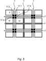
- the goods storage system 1 comprises a travel level 6 arranged above the storage shafts 3, which guides 7 ( Fig. 5 ) which are designed to drive a driverless vehicle 8 within the driving plane 6 selectively in a first direction of travel in order to be able to change between a plurality of shaft openings 4 of a plurality of storage shafts 3 arranged in a row, and in a second direction of travel in order to be able to change between a plurality of shaft openings 4 of a plurality of storage shafts 3 arranged in a column.
- the goods storage system 1 accordingly has at least one driverless vehicle 8 which is designed and configured to travel automatically in the travel plane 6 along the guides 7, so that the driverless vehicle 8 can be moved to the shaft opening 4 of any storage shaft 2 of the goods storage facility 2 by the driverless vehicle 8 traveling self-propelled either in the first direction of travel and/or in the second direction of travel along the guides 7.
- the goods storage system 1 comprises a plurality of lifting devices 9 arranged on the goods storage 2, each of which is designed to lift and lower at least one stack of a plurality of containers 5 stored in a respective storage shaft 3.
- the plurality of lifting devices 9 are designed without a drive, and each lifting device 9 or a respective group of several lifting devices 9 has a drive coupling 10 which is designed to feed a drive torque into the lifting device 9, wherein the drive couplings 10 are accessible from the travel level 6.
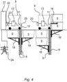
- the at least one driverless vehicle 8 has a lifting drive 11 with a drive counter-coupling 12 corresponding to the drive couplings 10 of the lifting devices 9, which is designed for automatic coupling to one of the drive couplings 10 of the lifting devices 9 when the driverless vehicle 8 is in coupling proximity to the respective drive coupling 10 of the lifting device 9.
- the drive counter-coupling 12 is mounted on the driverless vehicle 8 by means of an adjusting device 25 so as to be automatically adjustable between a coupling position in which the drive counter-coupling 12 is in engagement with the drive coupling 10 of a lifting device 9 when the driverless vehicle 8 is in coupling proximity to the respective drive coupling 10 of the lifting device 9, and a release position in which the drive counter-coupling 12 is separated from the drive coupling 10 of the lifting device 9.
- the driverless vehicle 8 has an electrical energy storage device 13.
- the lifting drive 11 is designed as an electric motor, to whose motor shaft the drive counter-coupling 12 is connected, wherein the lifting drive 11, i.e., the electric motor, is connected to the electrical energy storage device 12.
- the driverless vehicle 8 can have a frame-like structure 14 which has a passage opening 15 in the center, through which containers 5 can be removed from the storage shaft 3 through the frame-like structure 14 of the driverless vehicle 8 and/or containers 5 can be inserted into the storage shaft 3.
- a support arm 16 can accordingly extend inwards, starting from the frame-like outer structure 14 in the direction of the center into the passage opening 15, so that the support arm 16 can place a container 5 or a stack of several containers 5 centrally above the shaft opening 4 above which the driverless vehicle 8 is currently located.
- the respective drive coupling 10 of the lifting device 9 is connected to a lifting spindle 17 which extends along the height of at least one storage shaft 3, wherein a platform 18 extending into the storage shaft 3 for depositing containers 5 is mounted on the lifting spindle 17 in a height-adjustable manner, such that by driving the lifting spindle 17 via the drive coupling 10, the platform 18 can be raised within the storage shaft 3 in order to deposit the containers 5 deposited in a stack on the platform 18 via the Shaft opening 4 to be able to lift upwards out of the storage shaft 3, and/or lowered in order to be able to lower the containers 5 placed in a stack on the platform 18 into the shaft opening 4 and downwards into the storage shaft 3.
- the Fig. 3 shows a modified embodiment in which the respective drive coupling 10 of the lifting device 9 is connected to a lifting spindle 17 which extends along the height of at least one storage shaft 3, wherein at least one auxiliary lifting spindle 17a also extends on the storage shaft 3 and can be driven together with the lifting spindle 17, wherein the lifting spindle 17 and the auxiliary lifting spindle 17a are arranged opposite the stack of containers 5 in the storage shaft 3 and each have a spindle thread which is designed to engage support sections 19 on lateral edge regions of the containers 5, such that containers 5 engaging in the spindle threads of the lifting spindle 17 and the auxiliary lifting spindle 17a can be raised and/or lowered in an individually supporting manner by rotating the lifting spindle 17 and the auxiliary lifting spindle 17a.
- the lifting spindles 17 and the auxiliary lifting spindles 17a end at a vertical height H above the floor 20 of the goods storage 2, which is at least as high as the height of a container 5, so that the containers 5 guided by the lifting spindles 17 and the auxiliary lifting spindles 17a can be released from engagement with the spindle threads of the lifting spindles 17 and auxiliary lifting spindles 17a in a height position close to the floor in order to be able to discharge a respective container 5 released from the lifting spindles 17 and auxiliary lifting spindles 17a from the goods storage 2 at a lower level.
- the goods storage system 1 can have at least one charging station 21 arranged on the goods storage 2, which is designed and configured to charge the electrical energy storage device 13 of the driverless vehicle 8, in the case of Fig. 4 the vehicle 8 shown on the left, wherein the charging station 21 has an electrical connector 22, via which electrical energy can be delivered from the charging station 21, and the driverless vehicle 8 has an electrical mating connector 23 corresponding to the electrical connector 22 of the charging station 21, wherein the electrical mating connector 23 of the driverless vehicle 8 can be electrically coupled to the electrical connector 22 of the charging station 21 when the driverless vehicle 8 is in coupling proximity to the respective drive coupling 10 of the lifting device 9, as is shown in Fig. 4 driverless vehicle 8 shown on the left.
- the electric motor of the lifting drive 9 can be designed and configured to draw electrical energy directly from an electrical network 24 to which the charging station 21 is connected when the electrical mating connector 23 of the driverless vehicle 8 is coupled to the electrical connector 22 of the charging station 21.
- each storage shaft 3 can have an at least substantially rectangular cross-section
- four storage shafts 3 can each form a quadrant on the travel level 6 with their shaft openings 4, wherein the four lifting spindles 17 assigned to the four storage shafts 3 are arranged close to the center of the quadrant, such that in a view from above the first quadrant I arranged storage shaft 3 has its first lifting spindle 17.1 in the lower left corner, the second storage shaft 3 arranged in the second quadrant II has its second lifting spindle 17.2 in the lower right corner, the third storage shaft 3 arranged in the third quadrant III has its third lifting spindle 17.3 in the upper right corner and the fourth storage shaft 3 arranged in the fourth quadrant IV has its fourth lifting spindle 17.4 in the upper left corner.
- the driverless vehicle 8 can have at least one support arm 16 which is designed to receive at least one container 5 or a stack of several containers 5 simultaneously in order to be able to transport them together within the driving plane 6.
- FIG. 6 schematically shows the method for raising and/or lowering at least one container 5 or a stack of several containers 5 within a storage shaft 3 in a goods storage 2 of a goods storage system 1.
- a driverless vehicle 8 is automatically driven, which is designed and configured for automatic driving in a driving plane 6 above storage shafts 3 of the goods storage facility 2 along guides 7 in the driving plane 6, so that the driverless vehicle 8 can be moved to an upper shaft opening 4 of any storage shaft 3 of the goods storage facility 2 by driving the driverless vehicle 8 self-propelled either in the first direction of travel and/or in the second direction of travel along the guides 7.
- a second step S2 of the method an automatic coupling of a drive counter-coupling 12 of the driverless Vehicle 8, which can be driven by a lifting drive 11 of the driverless vehicle 8, to a drive coupling 10 of a lifting device 9 of the goods storage 2, which is arranged stationary in the relevant storage shaft 3, in such a way that a torque can be transmitted from the lifting drive 11 of the driverless vehicle 8 to the lifting device 9 of the goods storage 2 in order to be able to selectively raise or lower a container 5 present in the storage shaft 3 or a stack of several containers 5 present in the storage shaft 3 by means of the lifting device 9.
- a third step S3 of the method the lifting drive 11 of the driverless vehicle 8 is automatically driven in order to raise or lower the container 5 present in the storage shaft 3 or the stack of several containers 5 present in the storage shaft 3 by means of the lifting device 9.
- electrical energy can be automatically extracted from a stationary charging station 21 of the goods storage device 1 into an electrical energy storage device 13 of the driverless vehicle 8 and/or into the lifting drive 11 of the driverless vehicle 8, while the lifting drive 11 of the driverless vehicle 8 drives the lifting device 9 of the goods storage device 2 for raising or lowering a container 5 present in the storage shaft 3 or the stack of several containers 5 present in the storage shaft 3.
Landscapes
- Engineering & Computer Science (AREA)
- Mechanical Engineering (AREA)
- Physics & Mathematics (AREA)
- Mathematical Physics (AREA)
- Warehouses Or Storage Devices (AREA)
Priority Applications (3)
| Application Number | Priority Date | Filing Date | Title |
|---|---|---|---|
| EP23208343.6A EP4553005A1 (fr) | 2023-11-07 | 2023-11-07 | Système de stockage de marchandises et procédé pour soulever et/ou abaisser au moins un conteneur dans un magasin de marchandises du système de stockage de marchandises |
| US18/938,751 US20250145375A1 (en) | 2023-11-07 | 2024-11-06 | Goods Storage System and Method |
| CN202411582316.6A CN119953746A (zh) | 2023-11-07 | 2024-11-07 | 货物存储系统和用于在货物存储系统的货物仓库中提升和/或降低至少一个容器的方法 |
Applications Claiming Priority (1)
| Application Number | Priority Date | Filing Date | Title |
|---|---|---|---|
| EP23208343.6A EP4553005A1 (fr) | 2023-11-07 | 2023-11-07 | Système de stockage de marchandises et procédé pour soulever et/ou abaisser au moins un conteneur dans un magasin de marchandises du système de stockage de marchandises |
Publications (1)
| Publication Number | Publication Date |
|---|---|
| EP4553005A1 true EP4553005A1 (fr) | 2025-05-14 |
Family
ID=88745825
Family Applications (1)
| Application Number | Title | Priority Date | Filing Date |
|---|---|---|---|
| EP23208343.6A Pending EP4553005A1 (fr) | 2023-11-07 | 2023-11-07 | Système de stockage de marchandises et procédé pour soulever et/ou abaisser au moins un conteneur dans un magasin de marchandises du système de stockage de marchandises |
Country Status (3)
| Country | Link |
|---|---|
| US (1) | US20250145375A1 (fr) |
| EP (1) | EP4553005A1 (fr) |
| CN (1) | CN119953746A (fr) |
Citations (3)
| Publication number | Priority date | Publication date | Assignee | Title |
|---|---|---|---|---|
| EP3995415A1 (fr) * | 2019-09-19 | 2022-05-11 | Beijing Jingdong Qianshi Technology Co., Ltd. | Système de stockage |
| EP3820791B1 (fr) | 2018-07-11 | 2023-06-07 | O.W. Machinebouw B.V. | Système de stockage et méthode pour opérer ledit stockage |
| NO20220036A1 (fr) * | 2022-01-11 | 2023-07-12 |
-
2023
- 2023-11-07 EP EP23208343.6A patent/EP4553005A1/fr active Pending
-
2024
- 2024-11-06 US US18/938,751 patent/US20250145375A1/en active Pending
- 2024-11-07 CN CN202411582316.6A patent/CN119953746A/zh active Pending
Patent Citations (3)
| Publication number | Priority date | Publication date | Assignee | Title |
|---|---|---|---|---|
| EP3820791B1 (fr) | 2018-07-11 | 2023-06-07 | O.W. Machinebouw B.V. | Système de stockage et méthode pour opérer ledit stockage |
| EP3995415A1 (fr) * | 2019-09-19 | 2022-05-11 | Beijing Jingdong Qianshi Technology Co., Ltd. | Système de stockage |
| NO20220036A1 (fr) * | 2022-01-11 | 2023-07-12 |
Also Published As
| Publication number | Publication date |
|---|---|
| US20250145375A1 (en) | 2025-05-08 |
| CN119953746A (zh) | 2025-05-09 |
Similar Documents
| Publication | Publication Date | Title |
|---|---|---|
| EP4086200B1 (fr) | Procédé d'accès à un récipient dans un système de stockage et de récupération et véhicule de transport destiné à être utilisé dans un système de stockage et de retrait pour récipients, ainsi que système de stockage et de retrait | |
| EP4328154B1 (fr) | Système de stockage permettant de stocker des récipients | |
| EP3786086A1 (fr) | Systèmes de stockage et/ou de préparation de commandes | |
| EP4219347B1 (fr) | Système de stockage permettant de stocker des récipient | |
| EP4067264A1 (fr) | Dispositif de tri | |
| EP3782929A1 (fr) | Chariot de chargement en entrepôt de piles de récipient | |
| EP0589844B1 (fr) | Magasin à haute performance avec des moyens pour stocker et prélever des marchandises | |
| WO2022090033A1 (fr) | Système de stockage pour le stockage de marchandises dans une installation de stockage tridimensionnelle | |
| CH669178A5 (de) | Kreuzspulen herstellende textilmaschine. | |
| DE102018131175B4 (de) | Garnspulentransportvorrichtung | |
| EP2746193B1 (fr) | Véhicule pour entrepôt, transstockeur, entrepôt et procédé correspondant | |
| DE102022213844B4 (de) | Vorrichtung zum Kommissionieren | |
| DE1784146A1 (de) | Mehrstoeckige Einrichtung zum Aufnehmen von Kraftfahrzeugen,Behaeltern od.dgl. | |
| DE102020126248A1 (de) | Mobiles Transportfahrzeug | |
| CH669179A5 (de) | Kreuzspulen herstellende textilmaschine. | |
| WO2021214079A1 (fr) | Agencement de deux cadres de guidage et de support et d'un véhicule d'ascenseur | |
| DE102006000654B4 (de) | Verfahren und Anordnung zum Wenden von Paletten | |
| DE102020122556A1 (de) | Warenlager, Lagerelement sowie Verfahren zum Betrieb eines Warenlagers | |
| EP0283042B1 (fr) | Méthode et dispositif pour la palettisation de couches unitaires | |
| WO2021151533A1 (fr) | Installation de stationnement pour véhicules automobiles | |
| DE102022201404B3 (de) | Lager- und Entnahmesystem sowie Station für ein Lager- und Entnahmesystem | |
| DE3402996A1 (de) | Anlage zum ein- und auslagern von containern unter verwendung eines hochregallagers | |
| DE102012112828A1 (de) | Lager und Lagerbediengeräte mit Passierfunktion | |
| AT408009B (de) | Parkgarage mit rostsystem | |
| DE19711464C2 (de) | Verfahren zum Stapeln von Transportkisten und Transportkistenstapellager |
Legal Events
| Date | Code | Title | Description |
|---|---|---|---|
| PUAI | Public reference made under article 153(3) epc to a published international application that has entered the european phase |
Free format text: ORIGINAL CODE: 0009012 |
|
| STAA | Information on the status of an ep patent application or granted ep patent |
Free format text: STATUS: THE APPLICATION HAS BEEN PUBLISHED |
|
| AK | Designated contracting states |
Kind code of ref document: A1 Designated state(s): AL AT BE BG CH CY CZ DE DK EE ES FI FR GB GR HR HU IE IS IT LI LT LU LV MC ME MK MT NL NO PL PT RO RS SE SI SK SM TR |
|
| STAA | Information on the status of an ep patent application or granted ep patent |
Free format text: STATUS: REQUEST FOR EXAMINATION WAS MADE |
|
| 17P | Request for examination filed |
Effective date: 20251112 |
|
| GRAP | Despatch of communication of intention to grant a patent |
Free format text: ORIGINAL CODE: EPIDOSNIGR1 |
|
| STAA | Information on the status of an ep patent application or granted ep patent |
Free format text: STATUS: GRANT OF PATENT IS INTENDED |
|
| INTG | Intention to grant announced |
Effective date: 20260217 |