EP4553268A2 - Système d'étanchéité et porte coulissante - Google Patents
Système d'étanchéité et porte coulissante Download PDFInfo
- Publication number
- EP4553268A2 EP4553268A2 EP24211094.8A EP24211094A EP4553268A2 EP 4553268 A2 EP4553268 A2 EP 4553268A2 EP 24211094 A EP24211094 A EP 24211094A EP 4553268 A2 EP4553268 A2 EP 4553268A2
- Authority
- EP
- European Patent Office
- Prior art keywords
- sealing
- profile
- central
- sliding door
- section
- Prior art date
- Legal status (The legal status is an assumption and is not a legal conclusion. Google has not performed a legal analysis and makes no representation as to the accuracy of the status listed.)
- Pending
Links
Images


Classifications
-
- E—FIXED CONSTRUCTIONS
- E06—DOORS, WINDOWS, SHUTTERS, OR ROLLER BLINDS IN GENERAL; LADDERS
- E06B—FIXED OR MOVABLE CLOSURES FOR OPENINGS IN BUILDINGS, VEHICLES, FENCES OR LIKE ENCLOSURES IN GENERAL, e.g. DOORS, WINDOWS, BLINDS, GATES
- E06B7/00—Special arrangements or measures in connection with doors or windows
- E06B7/16—Sealing arrangements on wings or parts co-operating with the wings
-
- E—FIXED CONSTRUCTIONS
- E06—DOORS, WINDOWS, SHUTTERS, OR ROLLER BLINDS IN GENERAL; LADDERS
- E06B—FIXED OR MOVABLE CLOSURES FOR OPENINGS IN BUILDINGS, VEHICLES, FENCES OR LIKE ENCLOSURES IN GENERAL, e.g. DOORS, WINDOWS, BLINDS, GATES
- E06B1/00—Border constructions of openings in walls, floors, or ceilings; Frames to be rigidly mounted in such openings
- E06B1/70—Sills; Thresholds
-
- E—FIXED CONSTRUCTIONS
- E06—DOORS, WINDOWS, SHUTTERS, OR ROLLER BLINDS IN GENERAL; LADDERS
- E06B—FIXED OR MOVABLE CLOSURES FOR OPENINGS IN BUILDINGS, VEHICLES, FENCES OR LIKE ENCLOSURES IN GENERAL, e.g. DOORS, WINDOWS, BLINDS, GATES
- E06B3/00—Window sashes, door leaves, or like elements for closing wall or like openings; Layout of fixed or moving closures, e.g. windows in wall or like openings; Features of rigidly-mounted outer frames relating to the mounting of wing frames
- E06B3/04—Wing frames not characterised by the manner of movement
- E06B3/06—Single frames
- E06B3/08—Constructions depending on the use of specified materials
- E06B3/20—Constructions depending on the use of specified materials of plastics
- E06B3/22—Hollow frames
- E06B3/221—Hollow frames with the frame member having local reinforcements in some parts of its cross-section or with a filled cavity
- E06B3/222—Hollow frames with the frame member having local reinforcements in some parts of its cross-section or with a filled cavity with internal prefabricated reinforcing section members inserted after manufacturing of the hollow frame
-
- E—FIXED CONSTRUCTIONS
- E06—DOORS, WINDOWS, SHUTTERS, OR ROLLER BLINDS IN GENERAL; LADDERS
- E06B—FIXED OR MOVABLE CLOSURES FOR OPENINGS IN BUILDINGS, VEHICLES, FENCES OR LIKE ENCLOSURES IN GENERAL, e.g. DOORS, WINDOWS, BLINDS, GATES
- E06B3/00—Window sashes, door leaves, or like elements for closing wall or like openings; Layout of fixed or moving closures, e.g. windows in wall or like openings; Features of rigidly-mounted outer frames relating to the mounting of wing frames
- E06B3/04—Wing frames not characterised by the manner of movement
- E06B3/263—Frames with special provision for insulation
- E06B3/26347—Frames with special provision for insulation specially adapted for sliding doors or windows
-
- E—FIXED CONSTRUCTIONS
- E06—DOORS, WINDOWS, SHUTTERS, OR ROLLER BLINDS IN GENERAL; LADDERS
- E06B—FIXED OR MOVABLE CLOSURES FOR OPENINGS IN BUILDINGS, VEHICLES, FENCES OR LIKE ENCLOSURES IN GENERAL, e.g. DOORS, WINDOWS, BLINDS, GATES
- E06B3/00—Window sashes, door leaves, or like elements for closing wall or like openings; Layout of fixed or moving closures, e.g. windows in wall or like openings; Features of rigidly-mounted outer frames relating to the mounting of wing frames
- E06B3/32—Arrangements of wings characterised by the manner of movement; Arrangements of movable wings in openings; Features of wings or frames relating solely to the manner of movement of the wing
- E06B3/34—Arrangements of wings characterised by the manner of movement; Arrangements of movable wings in openings; Features of wings or frames relating solely to the manner of movement of the wing with only one kind of movement
- E06B3/42—Sliding wings; Details of frames with respect to guiding
- E06B3/46—Horizontally-sliding wings
- E06B3/469—Arrangements at the overlapping vertical edges of the wings that engage when closing
-
- E—FIXED CONSTRUCTIONS
- E06—DOORS, WINDOWS, SHUTTERS, OR ROLLER BLINDS IN GENERAL; LADDERS
- E06B—FIXED OR MOVABLE CLOSURES FOR OPENINGS IN BUILDINGS, VEHICLES, FENCES OR LIKE ENCLOSURES IN GENERAL, e.g. DOORS, WINDOWS, BLINDS, GATES
- E06B7/00—Special arrangements or measures in connection with doors or windows
- E06B7/16—Sealing arrangements on wings or parts co-operating with the wings
- E06B7/22—Sealing arrangements on wings or parts co-operating with the wings by means of elastic edgings, e.g. elastic rubber tubes; by means of resilient edgings, e.g. felt or plush strips, resilient metal strips
- E06B7/23—Plastic, sponge rubber, or like strips or tubes
- E06B7/2305—Plastic, sponge rubber, or like strips or tubes with an integrally formed part for fixing the edging
-
- E—FIXED CONSTRUCTIONS
- E06—DOORS, WINDOWS, SHUTTERS, OR ROLLER BLINDS IN GENERAL; LADDERS
- E06B—FIXED OR MOVABLE CLOSURES FOR OPENINGS IN BUILDINGS, VEHICLES, FENCES OR LIKE ENCLOSURES IN GENERAL, e.g. DOORS, WINDOWS, BLINDS, GATES
- E06B7/00—Special arrangements or measures in connection with doors or windows
- E06B7/16—Sealing arrangements on wings or parts co-operating with the wings
- E06B7/22—Sealing arrangements on wings or parts co-operating with the wings by means of elastic edgings, e.g. elastic rubber tubes; by means of resilient edgings, e.g. felt or plush strips, resilient metal strips
- E06B7/23—Plastic, sponge rubber, or like strips or tubes
- E06B7/2305—Plastic, sponge rubber, or like strips or tubes with an integrally formed part for fixing the edging
- E06B7/2307—Plastic, sponge rubber, or like strips or tubes with an integrally formed part for fixing the edging with a single sealing-line or -plane between the wing and the part co-operating with the wing
- E06B7/2309—Plastic, sponge rubber, or like strips or tubes with an integrally formed part for fixing the edging with a single sealing-line or -plane between the wing and the part co-operating with the wing with a hollow sealing part
-
- E—FIXED CONSTRUCTIONS
- E06—DOORS, WINDOWS, SHUTTERS, OR ROLLER BLINDS IN GENERAL; LADDERS
- E06B—FIXED OR MOVABLE CLOSURES FOR OPENINGS IN BUILDINGS, VEHICLES, FENCES OR LIKE ENCLOSURES IN GENERAL, e.g. DOORS, WINDOWS, BLINDS, GATES
- E06B7/00—Special arrangements or measures in connection with doors or windows
- E06B7/16—Sealing arrangements on wings or parts co-operating with the wings
- E06B7/22—Sealing arrangements on wings or parts co-operating with the wings by means of elastic edgings, e.g. elastic rubber tubes; by means of resilient edgings, e.g. felt or plush strips, resilient metal strips
- E06B7/23—Plastic, sponge rubber, or like strips or tubes
- E06B7/2305—Plastic, sponge rubber, or like strips or tubes with an integrally formed part for fixing the edging
- E06B7/2312—Plastic, sponge rubber, or like strips or tubes with an integrally formed part for fixing the edging with two or more sealing-lines or -planes between the wing and part co-operating with the wing
-
- E—FIXED CONSTRUCTIONS
- E06—DOORS, WINDOWS, SHUTTERS, OR ROLLER BLINDS IN GENERAL; LADDERS
- E06B—FIXED OR MOVABLE CLOSURES FOR OPENINGS IN BUILDINGS, VEHICLES, FENCES OR LIKE ENCLOSURES IN GENERAL, e.g. DOORS, WINDOWS, BLINDS, GATES
- E06B7/00—Special arrangements or measures in connection with doors or windows
- E06B7/26—Rain or draught deflectors, e.g. under sliding wings also protection against light for doors
-
- E—FIXED CONSTRUCTIONS
- E06—DOORS, WINDOWS, SHUTTERS, OR ROLLER BLINDS IN GENERAL; LADDERS
- E06B—FIXED OR MOVABLE CLOSURES FOR OPENINGS IN BUILDINGS, VEHICLES, FENCES OR LIKE ENCLOSURES IN GENERAL, e.g. DOORS, WINDOWS, BLINDS, GATES
- E06B3/00—Window sashes, door leaves, or like elements for closing wall or like openings; Layout of fixed or moving closures, e.g. windows in wall or like openings; Features of rigidly-mounted outer frames relating to the mounting of wing frames
- E06B3/30—Coverings, e.g. protecting against weather, for decorative purposes
- E06B3/301—Coverings, e.g. protecting against weather, for decorative purposes consisting of prefabricated profiled members or glass
- E06B3/306—Covering plastic frames with metal or plastic profiled members
Definitions
- the invention relates to a sealing system for sealing between the opposing center profiles of a sliding door, comprising a sealing profile which can be fastened to one of the center profiles, preferably to the center profile of the fixed panel of the sliding door, in the vertical direction of extension.
- the invention further relates to a sliding door comprising a frame in which a fixed panel and one or two sliding panels are arranged, which have overlapping center profiles when closed.
- the center profiles are arranged overlapping in a direction perpendicular to the sliding direction, in particular in a direction perpendicular to the surface of the glass elements in a sliding door.
- Such a sliding door is preferably a parallel-action sliding door, formed from a circumferential frame, which accommodates at least a first and a second leaf that are offset from one another, wherein the first leaf preferably forms a non-displaceable fixed field or a sliding leaf and can preferably comprise a glass element that is held in the central region by a central profile with a cover strip and a glazing bead, and the second leaf forms a displaceable sliding leaf composed of individual profiles that is displaceably mounted in the frame.
- This preferably also comprises a glass element.
- the closed sliding door position it is provided that the connection between the interior of the room and the environment formed by the distance between the opposing central profiles is closed by means of a sealing system.
- the movable sliding door leaf especially a so-called parallel-retractable sliding door, fits into the frame parallel to the fixed leaf.
- the retractable function is achieved by turning the handle. This detaches the sliding leaf from the frame of the entire sliding door and allows it to be moved sideways.
- the invention is particularly intended for sliding doors whose opposite central profiles or whose leaves, when the sliding door is closed or in the closed state, have a smaller distance, in particular a smaller parallel offset, from one another than in an open position in which the sliding leaf is displaceable.
- the respective vertical frame sections in the central area of the sliding door lie in front of each other in offset planes, whereby they each form the aforementioned central area on their opposite/towards-facing surfaces in order to create both a visually and mechanically effective overlap and a seal against wind and rain when closed.
- the object of the invention is therefore to improve the air and driving rain tightness of a sliding door.
- the sealing profile comprises a sealing base which can be fastened with its rear side to the central profile, in particular to a cover profile of the central profile, and which has two projecting sealing regions running parallel to one another at a distance from one another on its front side, wherein a recess is formed between the sealing regions and the front side of the sealing base, viewed in cross section, in particular with which recess a pressure equalization chamber can be formed in cooperation with a surface of an opposite central profile, wherein two sealing elements are further provided and with each sealing element the front cross section of the sealing profile can be partially covered in contact at a respective end lying in the direction of extension, in particular is partially covered when used as intended.
- the sealing profile can be/is attached directly to the center profile, in particular to a cover profile of the center profile, without the need for additional components.
- the sealing profile and the two sealing elements form the sole components of the sealing system according to the invention.
- the invention is achieved by a sliding door of the type mentioned at the outset, in which a sealing profile of the aforementioned sealing system is arranged on one of the central profiles, in particular the central profile of a fixed field, running in the vertical direction, the open cross section of which is partially closed on the room side at the respective end of the sealing profile with a respective sealing element of the aforementioned sealing system, which is arranged between the end of the sealing profile and the frame.
- Such a sealing profile is preferably formed in a direction of extension that runs vertically after installation on the central profile, e.g., the central profile of a fixed panel of the sliding door.
- the sealing profile has a profile cross-section perpendicular to the direction of extension that remains constant over the entire extension.
- Such a sealing profile can be manufactured, for example, by extrusion, preferably from an elastomer material.
- a sealing profile is preferably a one-piece component made of an elastomer material.
- the sealing base mentioned can, for example, form a web when viewed in the profile cross-section, which runs parallel to a surface of the central profile, in particular to both opposite surfaces of the opposite central profiles.
- sealing regions extend from the sealing base toward the opposite center profile.
- the sealing regions preferably extend parallel to one another in the aforementioned direction of extension and are preferably spaced perpendicular to this direction and in a direction parallel to the opposing surfaces of the two center profiles.
- the invention thus makes it possible that in a closed position of a sliding door with this sealing system, the pressure compensation space formed by the recess and the opposite surface of the central profile is open to the weather side at the respective end of the sealing profile and is closed to the room side by the respective sealing element.
- the pressure equalization chamber or recess formed in the closed state is permeable to diffusion on the weather side, so that any moisture that has penetrated can dry out to the outside.
- the sealing profile is preferably designed such that the two sealing regions each form a leg that extends from the sealing base connecting these legs toward the opposite center profile.
- the surface of the respective sealing region that contacts the surface of the opposite center profile has a sealing interaction with the surface of the center profile.
- each leg can have, particularly at its free end, at least one sealing lip that can be placed against the surface.
- the sealing system comprises a sealing profile in the overlapping area of the center profiles, preferably of the fixed panel and the sliding sash.
- each sealing element is formed by a body stepped in a height direction, in particular made of an elastomeric material, wherein the body is tapered in the height direction, for which purpose after each step the thickness of the body, viewed in a thickness direction, is decreasing, in particular wherein the thickness direction corresponds to the direction of the spacing between two opposing central profiles, wherein the narrowest step in the thickness direction and the highest step in the height direction forms a contact surface with which the cross-section of the sealing profile can be partially covered by contact.
- the height direction is the direction in which the two sealing elements are spaced from one another, in particular in which the sealing profile extends, thus preferably the vertical direction in the case of an installed sliding door.
- the contacting partial overlap of the cross-section of the sealing profile by a respective sealing element is such that at least the leg or sealing area of the sealing profile arranged on the room side and, in some areas, the web of the sealing base is contacted by the contact surface of the narrowest / uppermost step.
- the cross-section of the sealing profile is closed on the room side, in particular when the room-side sealing area/leg of the sealing profile makes sealing contact with the surface of the opposite central profile, preferably, wherein this surface of the central profile also lies in a sealed manner on the sealing element in an area beyond the front end of the sealing profile, in particular on a surface of the sealing element which lies in the height direction between the contact surface and the next lower step surface.
- the thickness of the narrowest step is less than or equal to the distance that the opposing surfaces of the central profiles have from each other, in particular at the location of the sealing element, in a closed state of a sliding door.
- the sealing profile preferably consists of an elastic material, in particular an elastomer material, preferably EPDM or soft PVC and is preferably used as a hand-drawn seal.
- the sealing profile is preferably detachably connectable to the central profile, preferably a cover profile of the central profile, using at least two fastening elements, e.g. locking elements.
- the sealing base preferably has, viewed in cross-section, a pin on its rear side, in particular a pin equipped with a hollow chamber, which can be pressed into a receiving recess on the central profile, in particular on a cover profile of a central profile.
- Such a receiving recess is preferably formed on the central profile or its cover profile as a vertically extending groove.
- the sealing base viewed in cross-section, has a hollow chamber on its rear side, in particular which is located laterally next to a preferably provided aforementioned pin in a direction parallel to the sealing base, with which the sealing base can be placed on the rear side against a contact surface, in particular a stepped contact surface of a central profile, in particular a cover profile of a central profile, in particular when used as intended.
- a web extends away from the rear of the sealing base, which web partially delimits the hollow chamber, in particular on the room side, and projects beyond it, wherein the free end of the web has an angled nose, in particular which extends parallel to the sealing base, which can be inserted into an undercut on the central profile, in particular into an undercut on a cover profile of a central profile, in particular is inserted in intended use.
- the lug When manually installing, the lug is preferably first hooked into the undercut of the cover profile, and then the pin is snapped into the receiving recess/groove of the cover profile. This installation method allows for easy replacement even in the event of damage to the seal.
- each of the two sealing areas/legs of the sealing profile comprises a hollow chamber, in particular wherein one of the two hollow chambers, in particular the hollow chamber facing the room side of the sealing profile, can be closed with the respective sealing element, in particular is closed when used as intended.
- such a hollow chamber creates an air-filled space, which improves the insulating properties of the sealing profile and also provides the sealing area with good flexibility, which supports the sealing function.
- hollow chambers are delimited in cross section by webs, wherein at least one of the webs of both hollow chambers, in particular the two webs of the sealing profile which point towards the recess and/or delimit it, is arranged at an acute angle to the sealing base.
- each sealing region in particular each hollow chamber, has at least one sealing lip on the side facing away from the front side of the sealing base, in particular the side facing the surface of an opposite central profile.
- the sealing area or the hollow chamber facing the weather side has two sealing lips whose free ends are spaced apart from one another in a plane parallel to the seal base.
- a double seal is achieved on the weather side.
- the sealing profile according to the invention thus preferably has four hollow chambers arranged inside the sealing profile.
- the hollow chambers serve as insulation, and the resulting web construction offers elastic deformability, supported by the soft material. Maximum mobility is achieved with minimal material expenditure.
- the at least two sealing lips preferably provided on the weather side of the sealing profile, which preferably spread apart from each other in opposite directions in the sealing state, form a widened sealing surface which is suitable for keeping rainwater out of the room.
- the sealing profile When the sliding door is closed, the sealing profile has an opening at the top and bottom ends of the pressure equalization chamber, facing only the weather side. This opening is not created by machining, for example, by subsequently inserting holes or slots, but rather by the upper end cross-section or lower end cross-section of the sealing profile being open and partially covered by an adjacent sealing element, thus providing a seal only toward the room side.
- the sealing element is preferably an elastically deformable component, preferably made of foam- or rubber-like material.
- the overlapping sealing elements cover from the room side, so that the open part of the sealing profile only faces and is connected to the weather side.
- the resulting upper and lower openings allow air to enter and exit the recess in the sealing profile or into the pressure equalization chamber formed by it.
- the pressure in the pressure equalization chamber which extends between the upper and lower openings, is the same as in the outside environment on the weather side. These openings function as pressure equalization openings, which, when the sealing profile is sealed, allow air to pass from the weather side in front of the sliding door into the pressure equalization chamber in the sliding door.
- the upper and lower openings ensure that the pressure in the pressure equalization chamber is the same as in the outside environment. No negative pressure is created. Capillary forces are reduced, thus preventing water from entering.
- the additional benefit is that weather-related moisture can be drained away via this channel in addition to the sealing lips mentioned above.
- the sealing profile has at least two elastic sealing lips, which are preferably and essentially arranged in a mirror image.
- the sealing profile preferably has at least one sealing lip, which, when sealed, rests against the surface/outer wall of the central profile of the sliding sash inside the pressure equalization chamber.
- the air pressure in the pressure equalization chamber preferably causes the sealing lip to be pressed against the outer wall of the sliding sash.
- Watertightness is primarily achieved through the sealing lips.
- a complementary effect is provided by the pressure equalization chamber, which ensures the same air pressure both inside and outside the room and also serves as a drainage channel.
- the sealing lip located on the room side ensures the final airtightness.
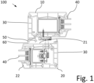
- FIG. 1 The central section of a sliding door according to the invention is shown in section.
- the frame is not visible in this view.
- the central profile 10 of the fixed panel and the central profile 20 of the sliding leaf are positioned relative to each other in such a way that they overlap.
- two sliding leaves can be provided that overlap with the central profiles in the central section.
- a gap 60 is formed between the mutually facing surfaces of both central profiles 10, 20, which, in the unsealed state, creates a connection between the interior of the room and the external environment.
- the Figure 1 shows an unlocked sliding door.
- a sealing profile 50 is attached, which serves to seal this gap, preferably in conjunction with a sealing profile not according to the invention on the cover profile 30 of the opposite central profile 20.
- the sealing profile 50 does not lie against the surface 21 of the opposite central profile 20, but has a gap 60 thereto.
- the "opposite" center profile always refers to the center profile to which the sealing profile 50 is not attached.
- the sealing profile thus always cooperates with the opposite center profile to form a seal by sealing contact with its surface.
- the opposite center profile is preferably the center profile of the sliding sash.
- a glass element 30 is also attached to the central profile 10 of the fixed panel, as is a glass element 40 to the central profile 20 of the sliding sash.
- the Figure 2 shows the same overlapped arrangement of the center profiles 10 and 20, but with the sliding door closed. In this closed position, the center profiles 10, 20 are spaced closer together, and the sealing profile 50 is therefore pressed with its sealing areas 58, 59 against the surface 21 of the opposite center profile 20.
- the Figure 2a shows an excerpt from Figure 2 with a detailed look at the sealing profile 50.
- the sealing profile 50 has a sealing base 57, which in the cross section shown here is formed perpendicular to the direction of extension of the sealing profile 50 by a web, which is a flat element in the actual sealing profile 50.
- This web of the sealing base 57 is parallel to the surface 21 of the opposite central profile 20.
- the sealing base 57 has a rear side with which the Sealing profile 50 is attached to the middle profile 10 and has a front side facing the opposite middle profile 20.
- a first sealing region 58 is arranged on the sealing base 57, and a second sealing region 59 is arranged at a distance therefrom. Both sealing regions 58, 59 extend parallel and spaced apart from one another in the direction of extension of the sealing profile 50.
- Both sealing areas 58, 59 can also be understood as legs of the sealing profile 50, which have a sealing interaction with the surface 21 of the opposite central profile 20 at their free ends.
- each sealing area 58, 59 has a hollow chamber I or II.
- the webs 52 and 52' of the hollow chambers I and II facing the recess A are preferably at an acute angle to the sealing base 57.
- the sealing base 57 has a pin 51 with a hollow chamber IV on the back and another adjacent hollow chamber III, which is bordered in cross section by webs and which is on a stepped opposite central profile 20 facing surface of the central profile 10 or the cover profile 30.
- the hollow chamber III is bounded on the room side by a web which projects from the sealing base 57, preferably at an obtuse angle thereto, beyond the hollow chamber III and has an angled nose 56, preferably running parallel to the sealing base, which engages in an undercut on the central profile 10 or its cover profile 30, which is open in the sliding direction.
- the pin 51 is pressed into a receiving recess 11, in particular a groove 11, on the central profile 10 or its cover profile 30 as a further fastening means.
- the sealing profile 50 ends on both sides at a distance from the surface of the profiles of the frame 90.
- a respective sealing element 70 in addition to the sealing profile 50 at its upper and lower ends.
- This respective sealing element 70 is arranged between the end face of the sealing profile cross-section and the surface of the frame 90 at the top and bottom, in such a way that the contact surface 71 of the sealing element 70 facing the end face of the sealing profile 50 closes the open end-face cross-section of the sealing profile 50 only on the room side.
- the contact surface 71 covers the open cross-section and the recess A over no more than half of the width of the sealing profile 50 in the sliding direction / perpendicular to the extension direction.
- the sealing element 70 has a height direction in which it extends from the lower support surface, with which it rests on the surface of the frame, towards the upper contact surface 71. In this height direction, the thickness of the sealing element decreases in a stepped manner towards the contact surface 71.
- the uppermost step preferably has a thickness which is less than or equal to the distance the surface 21 of the opposite central profile 20 to the stepped contact surface on the central profile 10 or the cover profile 30, against which the rear hollow chamber III rests.
- the sealing element 70 can be positioned with respect to Figure 2a be arranged under the right-hand part of the sealing profile 50, wherein the surface 21 of the opposite central profile 20, when the sliding door is closed, lies tightly against the sealing element 70 on its step surface below the contact surface 71.
- the pressure equalization chamber at the recess A is therefore closed to the right / room side and open to the left / weather side.
- the gradation of the sealing element 70 preferably corresponds to the gradation of the respective horizontal sash profile of the sliding sash on its side facing the frame.
- the Figure 6 shows such a sealing element 70 as a stepped body, the thickness of which decreases in a stepped manner upwards towards the contact surface 71.
- a projection 72 is preferably present on the weather side of the sealing element 70, the surface of which continues the contact surface 71 towards the weather side.
- This projection can preferably be clamped behind a top strip 91 that is placed on the frame 90.
- the sealing element 70 can preferably be enclosed between the top strip 92 and a strip 93 placed on the other side of the sealing element 70 on the frame 90.
Landscapes
- Engineering & Computer Science (AREA)
- Civil Engineering (AREA)
- Structural Engineering (AREA)
- Specific Sealing Or Ventilating Devices For Doors And Windows (AREA)
Applications Claiming Priority (1)
| Application Number | Priority Date | Filing Date | Title |
|---|---|---|---|
| DE102023130835.1A DE102023130835A1 (de) | 2023-11-07 | 2023-11-07 | Dichtungssystem und Schiebetür |
Publications (2)
| Publication Number | Publication Date |
|---|---|
| EP4553268A2 true EP4553268A2 (fr) | 2025-05-14 |
| EP4553268A3 EP4553268A3 (fr) | 2025-08-06 |
Family
ID=93432137
Family Applications (1)
| Application Number | Title | Priority Date | Filing Date |
|---|---|---|---|
| EP24211094.8A Pending EP4553268A3 (fr) | 2023-11-07 | 2024-11-06 | Système d'étanchéité et porte coulissante |
Country Status (2)
| Country | Link |
|---|---|
| EP (1) | EP4553268A3 (fr) |
| DE (1) | DE102023130835A1 (fr) |
Citations (2)
| Publication number | Priority date | Publication date | Assignee | Title |
|---|---|---|---|---|
| DE7725150U1 (de) | 1977-08-12 | 1978-01-19 | Golde Gmbh Spritzgusswerk, 8192 Geretsried | Zargen- und rahmenprofil fuer hebe- und/oder schiebefenster oder -tueren |
| EP3543451B1 (fr) | 2018-03-20 | 2020-10-07 | Veka AG | Unité de verrou médian pour un battant de porte levante et coulissante |
Family Cites Families (3)
| Publication number | Priority date | Publication date | Assignee | Title |
|---|---|---|---|---|
| DE102013018274B4 (de) * | 2013-10-31 | 2019-02-14 | Heroal - Johann Henkenjohann Gmbh & Co. Kg | Thermisch gedämmtes Profil |
| DE202015006206U1 (de) * | 2015-09-08 | 2015-10-05 | Siegenia-Aubi Kg | Dichtungsvorrichtung für einen verschiebbaren Flügel als Schiebeflügel oder verschiebbaren Hebe-Schiebeflügel eines Fensters oder einer Tür |
| DE202016101390U1 (de) * | 2016-03-13 | 2016-04-29 | Veka Ag | Mitteldichtungsblock und Mitteldichtungsblocksystem für eine Hebeschiebtür |
-
2023
- 2023-11-07 DE DE102023130835.1A patent/DE102023130835A1/de active Pending
-
2024
- 2024-11-06 EP EP24211094.8A patent/EP4553268A3/fr active Pending
Patent Citations (2)
| Publication number | Priority date | Publication date | Assignee | Title |
|---|---|---|---|---|
| DE7725150U1 (de) | 1977-08-12 | 1978-01-19 | Golde Gmbh Spritzgusswerk, 8192 Geretsried | Zargen- und rahmenprofil fuer hebe- und/oder schiebefenster oder -tueren |
| EP3543451B1 (fr) | 2018-03-20 | 2020-10-07 | Veka AG | Unité de verrou médian pour un battant de porte levante et coulissante |
Also Published As
| Publication number | Publication date |
|---|---|
| DE102023130835A1 (de) | 2025-05-08 |
| EP4553268A3 (fr) | 2025-08-06 |
Similar Documents
| Publication | Publication Date | Title |
|---|---|---|
| EP0841456B1 (fr) | Fenêtre du type jalousie pour des façades essentiellement verticales | |
| DE2920445A1 (de) | Verschlussanordnung mit verglasung | |
| EP3219893B1 (fr) | Bloc d'étanchéité central pour une porte à levage coulissante | |
| DE19624629C1 (de) | Abdichtsystem für Glasdächer und Glaswände | |
| AT511798B1 (de) | Bodenschwelle für eine hebe/schiebetür | |
| EP4553268A2 (fr) | Système d'étanchéité et porte coulissante | |
| DE2330370A1 (de) | Schiebefenster bzw. schiebetuer | |
| EP0757152A1 (fr) | Joint d'étanchéité profilé | |
| DE3415679A1 (de) | Profilleiste zum dichtenden einfassen einer fensterscheibe oder eines tuerelementes | |
| AT506900B1 (de) | Fassadenplattentragkonstruktion | |
| AT17077U1 (de) | System zur Montage einer Fensterbank an einer Außenfassade | |
| EP3299568B1 (fr) | Fenêtre de toit | |
| DE102016125334A1 (de) | Fenster oder Tür mit einer Dichtungsanordnung und Falzdichtung | |
| EP3854960A1 (fr) | Caniveau pour surfaces de façade et/ou de terrasse et système de caniveau | |
| DE29717672U1 (de) | Abzugsvorrichtung zur dachseitigen Entlüftung | |
| DE29716361U1 (de) | Gebäudefenster und/oder Gebäudefenstertür | |
| EP2292859B1 (fr) | Fenêtre de toit d'habitation dotée d'un dormant | |
| EP4509672A1 (fr) | Élément de façade et façade d'élément | |
| DE2601795C2 (de) | Dichtung am Mittelstoss von Fenstern oder Türen mit horizontal verschiebbaren Flügeln | |
| EP0340473B1 (fr) | Façade rideau | |
| EP4245957A1 (fr) | Cadre de porte avec seuil | |
| DE2703111A1 (de) | Rahmen fuer einen fenster- oder tuerfluegel | |
| EP3299569B1 (fr) | Fenêtre de toît | |
| EP4026979A1 (fr) | Installation de porte hermétique | |
| EP0833017A2 (fr) | Dispositif de fixation |
Legal Events
| Date | Code | Title | Description |
|---|---|---|---|
| PUAI | Public reference made under article 153(3) epc to a published international application that has entered the european phase |
Free format text: ORIGINAL CODE: 0009012 |
|
| STAA | Information on the status of an ep patent application or granted ep patent |
Free format text: STATUS: THE APPLICATION HAS BEEN PUBLISHED |
|
| AK | Designated contracting states |
Kind code of ref document: A2 Designated state(s): AL AT BE BG CH CY CZ DE DK EE ES FI FR GB GR HR HU IE IS IT LI LT LU LV MC ME MK MT NL NO PL PT RO RS SE SI SK SM TR |
|
| PUAL | Search report despatched |
Free format text: ORIGINAL CODE: 0009013 |
|
| AK | Designated contracting states |
Kind code of ref document: A3 Designated state(s): AL AT BE BG CH CY CZ DE DK EE ES FI FR GB GR HR HU IE IS IT LI LT LU LV MC ME MK MT NL NO PL PT RO RS SE SI SK SM TR |
|
| RIC1 | Information provided on ipc code assigned before grant |
Ipc: E06B 7/16 20060101AFI20250701BHEP Ipc: E06B 3/263 20060101ALI20250701BHEP Ipc: E06B 3/46 20060101ALI20250701BHEP Ipc: E06B 1/70 20060101ALI20250701BHEP Ipc: E06B 7/23 20060101ALI20250701BHEP Ipc: E06B 7/26 20060101ALI20250701BHEP |
|
| STAA | Information on the status of an ep patent application or granted ep patent |
Free format text: STATUS: REQUEST FOR EXAMINATION WAS MADE |
|
| 17P | Request for examination filed |
Effective date: 20260204 |