EP4553321A1 - Pompe à vide à haute puissance et densité - Google Patents
Pompe à vide à haute puissance et densité Download PDFInfo
- Publication number
- EP4553321A1 EP4553321A1 EP25164818.4A EP25164818A EP4553321A1 EP 4553321 A1 EP4553321 A1 EP 4553321A1 EP 25164818 A EP25164818 A EP 25164818A EP 4553321 A1 EP4553321 A1 EP 4553321A1
- Authority
- EP
- European Patent Office
- Prior art keywords
- rotor
- holweck
- vacuum pump
- rotor hub
- pump
- Prior art date
- Legal status (The legal status is an assumption and is not a legal conclusion. Google has not performed a legal analysis and makes no representation as to the accuracy of the status listed.)
- Pending
Links
Images





Classifications
-
- F—MECHANICAL ENGINEERING; LIGHTING; HEATING; WEAPONS; BLASTING
- F04—POSITIVE - DISPLACEMENT MACHINES FOR LIQUIDS; PUMPS FOR LIQUIDS OR ELASTIC FLUIDS
- F04D—NON-POSITIVE-DISPLACEMENT PUMPS
- F04D19/00—Axial-flow pumps
- F04D19/02—Multi-stage pumps
- F04D19/04—Multi-stage pumps specially adapted to the production of a high vacuum, e.g. molecular pumps
- F04D19/042—Turbomolecular vacuum pumps
-
- F—MECHANICAL ENGINEERING; LIGHTING; HEATING; WEAPONS; BLASTING
- F04—POSITIVE - DISPLACEMENT MACHINES FOR LIQUIDS; PUMPS FOR LIQUIDS OR ELASTIC FLUIDS
- F04D—NON-POSITIVE-DISPLACEMENT PUMPS
- F04D19/00—Axial-flow pumps
- F04D19/02—Multi-stage pumps
- F04D19/04—Multi-stage pumps specially adapted to the production of a high vacuum, e.g. molecular pumps
- F04D19/044—Holweck-type pumps
-
- F—MECHANICAL ENGINEERING; LIGHTING; HEATING; WEAPONS; BLASTING
- F04—POSITIVE - DISPLACEMENT MACHINES FOR LIQUIDS; PUMPS FOR LIQUIDS OR ELASTIC FLUIDS
- F04D—NON-POSITIVE-DISPLACEMENT PUMPS
- F04D19/00—Axial-flow pumps
- F04D19/02—Multi-stage pumps
- F04D19/04—Multi-stage pumps specially adapted to the production of a high vacuum, e.g. molecular pumps
- F04D19/046—Combinations of two or more different types of pumps
Definitions
- the present invention relates to a vacuum pump, in particular a turbomolecular vacuum pump, with at least one Holweck pumping stage, which comprises a rotor with a rotor shaft and a rotor hub connected to the rotor shaft.
- vacuum pumps are used in many areas of industry and research. Due to limited space, it is often desirable to use vacuum pumps that are as compact as possible, while maintaining a minimum pumping capacity despite their small size.
- turbomolecular vacuum pumps with an integrated Holweck pumping stage already have a high packing and power density due to the integration of the Holweck pumping stage, there is nevertheless a continuing need to further reduce the size of turbomolecular vacuum pumps without this leading to a loss of pumping performance, which equates to an increase in power and packing density.
- the invention is therefore based on the object of providing a vacuum pump and in particular a turbomolecular vacuum pump which meets the previously described need.
- a vacuum pump in particular with a turbomolecular vacuum pump, which is characterized by the features of claim 1 and in particular by the fact that a plurality of uniformly spaced pump blades are provided along the outer circumference of the rotor hub.
- turbo blades operate according to the functional principle of a turbomolecular vacuum pump and can therefore also be referred to as turbo blades.
- the pump blades in question are part of the rotor hub of the Holweck pumping stage and are preferably formed integrally with the rotor hub, they are located downstream of the turbomolecular pumping stages of the pump and upstream of the Holweck pumping mechanism of the Holweck pumping stage, viewed in the pumping direction.
- the turbomolecular vacuum pump according to the invention thus comprises, in a sense, in addition to the already existing turbomolecular pumping stage and the Holweck pumping stage, an additional turbomolecular pumping stage in the form of turbo blades provided along the outer circumference of the rotor hub.
- This additional pumping stage increases the packing density of the pump, since the additional pumping stage occupies or takes up an installation space already available inside the turbomolecular vacuum pump. Since the additional pumping stage does not change the size of the turbomolecular vacuum pump, in particular does not increase it, the additional pumping stage in the form of the turbo blades in question also increases the power density of the pump in the desired manner.
- the rotor hub of the turbomolecular vacuum pump according to the invention thus fulfils, in addition to its actual function as a carrier for the Holweck rotor sleeves, also the function of a carrier for the turbo blades.
- the The rotor hub has several seals or ring webs, which, in conjunction with several stationary seals or ring webs, form a labyrinth seal to seal the motor section of the pump from the vacuum section.
- the rotor hub also serves as a balancing body to eliminate unwanted imbalances.
- the rotor hub according to the invention thus combines a multitude of different functionalities in one and the same component in a very small space, so that no additional volume areas inside the turbomolecular vacuum pump are occupied to realize the functions in question, which would otherwise have a negative impact on the size and thus on the power density of the pump.
- the balancing area is located on the outer circumference of the rotor hub, preferably between two pump blades adjacent to each other in the circumferential direction.
- the pump blades provided along the outer circumference of the rotor hub can be spaced apart from one another in the circumferential direction without overlapping.
- the at least one balancing region can be located in the non-overlapping region between two adjacent pump blades.
- a balancing area is located on the outer circumference of the rotor hub, according to a further embodiment it can be provided that a balancing area is located in the radial direction between the at least two Holweck rotor sleeves on the rotor hub.
- the rotor hub forms an annular retaining web for each Holweck rotor sleeve, each of which supports one of the existing Holweck rotor sleeves, wherein at least the radially outermost retaining web or the only retaining web, if only one Holweck rotor sleeve is present, has a radially outer exposed annular surface.
- the balancing region is located on the outer circumference of the rotor or in the radial direction between the at least two Holweck rotor sleeves, it can be provided according to another embodiment that the at least one balancing region is located on the radially outer exposed annular surface of the radially outermost retaining web or the only retaining web.
- the rotor hub forms at least one balancing ring concentric with the at least one Holweck rotor sleeve, on which the at least one balancing region is provided.
- the balancing ring is located radially between the two Holweck rotor sleeves, in particular on the side of the rotor hub opposite the Holweck rotor sleeves.
- the condition of the rotor is of particular importance for the pump's functionality. It is therefore of great importance to be able to reliably monitor its operation, for example, to To record load conditions and/or to be able to detect impending malfunctions at an early stage.
- the vacuum pump further comprises at least one surface-treated section on the rotor hub and at least one sensor device with which a temperature of the at least one surface-treated section of the rotor hub can be determined in a contactless manner by measuring the heat radiation emitted by the section.
- the rotor hub has an additional functionality, since the temperature of the rotor hub can be determined via the surface-treated section, which allows conclusions to be drawn about the operating condition of the pump, which, for example, allows impending malfunctions to be detected at an early stage.
- Providing the surface-treated section on the rotor hub proves particularly advantageous because any imbalances associated with the surface-treated section can be compensated by the at least one balancing area, as described above.
- material can be removed from the rotor hub in the balancing area immediately after the surface-treated section has been created using the same laser used to create the surface-treated section, thus compensating for the imbalance associated with the surface-treated section.
- emissivity is the ratio of the radiation emitted by the rotor to that emitted by an ideal heat radiator (blackbody).
- the emissivity of an ideal heat radiator is 1.
- the emissivity of at least one section of the rotor hub is achieved through a suitable surface treatment.
- the thermal radiation emitted by the surface-treated section is also easier and more reliably measured because the amount of emitted radiation, or radiation density, is significantly greater than that of an untreated surface section. This, in turn, allows the use of simple sensors if cost considerations are paramount. Conversely, temperature measurement is significantly more accurate and reproducible when using conventional sensors.
- the section extends in the circumferential direction of the rotor hub substantially uniformly around the axis of rotation of the robot with regard to its properties, or that several sections with comparable properties are arranged uniformly distributed in the circumferential direction.
- the sensor device comprises an infrared sensor.
- the section of the rotor hub is roughened or structured in order to thereby increase the emissivity of the section.
- One possible mechanism that could be responsible for the improved emission properties is increased diffuse reflection in the electromagnetic infrared range, in particular in the near to mid-infrared range, for example in wavelength ranges of approximately 8 to 15 ⁇ m.
- the section of the rotor hub is roughened or structured in such a way that it has an average roughness Ra of 5 to 25 ⁇ m and/or an average roughness depth Rz of 40 to 100 ⁇ m and/or that the section has surface structures in the range 15 to 50 ⁇ m.
- the surface-treated section consists essentially of a rotor hub material in the area of the section.
- the treated surface then essentially retains the chemical and/or mechanical stability of the original material, e.g., aluminum.
- the rotor hub is coated, for example, with nickel.
- the coating is applied over a large area, so that areas of the rotor hub that are used for temperature determination are also coated. In this case, this coating is considered part of the rotor hub material.
- a suitable surface treatment to increase the emissivity proves to be effective.
- the protective effect of the coating is not significantly impaired by the surface treatment if an appropriate treatment process is used.
- the roughening or structuring of the section may comprise a regular pattern, such as hatching. However, a uniform roughening or structuring is preferred.
- the aforementioned section of the rotor hub may have a coating, i.e., the surface treatment comprises a coating of the section (possibly in addition to a coating of the rotor that was applied prior to the surface treatment of the section, such as the nickel coating described above as an example).
- a dark paint or other suitable substances e.g., black nickel, oxide layers such as Kepla or anodized aluminum
- the coating can also be provided in addition to roughening and/or structuring the section, e.g., to protect it.
- the surface-treated section can form an annular surface. This makes it possible to continuously measure the temperature of the rotor hub as it rotates.
- the surface-treated section can be curved and/or flat at least in sections; in particular, it can be continuously curved or essentially completely flat.
- the surface-treated section extends in a plane which is arranged substantially perpendicular to a rotational axis of the rotor.
- a variation 1 relates to a vacuum pump, in particular a turbomolecular vacuum pump, with at least one Holweck pumping stage, which comprises a Holweck rotor and a Holweck stator; wherein the Holweck rotor comprises a rotor shaft with a hub provided thereon and at least two Holweck rotor sleeves provided on the hub, which concentrically surround the rotor shaft, wherein a radially inner Holweck rotor sleeve has a first diameter and a radially outer Holweck rotor sleeve has a second diameter; and wherein the Holweck stator comprises, between the two Holweck rotor sleeves, a Holweck stator sleeve concentric with them, which has a fixed end attached to a stationary housing section of the vacuum pump, a free end axially opposite the fixed end, and an inner surface with an internal thread formed thereon and an outer surface with an external thread formed thereon; and wherein the second
- Variation 2 concerns the vacuum pump according to Variation 1, wherein the second diameter of the radially outer Holweck rotor sleeve is at least 35% larger than the first diameter of the radially inner Holweck rotor sleeve.
- a variation 4 relates to the vacuum pump according to one of the variations 1 to 3, wherein at least two mutually concentric annular webs are formed at the free end of the Holweck stator sleeve and at least two mutually concentric annular webs are also formed at the hub, which are nested with the annular webs of the free end of the Holweck stator sleeve.
- Variation 5 relates to the vacuum pump according to one of the variations 1 to 4, wherein the Holweck stator sleeve is penetrated at its free end by several gas flow bores in the radial direction which are evenly spaced from one another in the circumferential direction.
- Variation 7 concerns the vacuum pump according to Variation 6, wherein the Holweck stator sleeve has a base ring portion attached to the stationary housing portion and a cantilever ring portion extending from an end face of the base ring portion facing the hub in the axial direction to the free end of the Holweck stator sleeve in the annular space between the inner Holweck rotor sleeve and the outer Holweck rotor sleeve.
- Variation 8 concerns the vacuum pump according to Variation 7, wherein the base ring section extends radially inwards from the external thread to over the inner Holweck rotor sleeve.
- Variation 9 concerns the vacuum pump according to Variation 7 or 8, wherein the cantilever ring portion and the base ring portion have the same outer diameter, wherein the external thread of the Holweck stator sleeve is formed on the outer surface of both the base ring portion and the cantilever ring portion.
- Variation 10 relates to the vacuum pump according to any one of variations 7 to 9, wherein the cantilever ring portion has a cylindrical inner surface with an internal thread formed thereon, wherein it is preferably provided that the number of threads of the internal thread corresponds to the number of threads of the external thread.
- Variation 11 relates to the vacuum pump according to any one of Variations 7 to 10, wherein the base ring portion forms an annular inner surface on which a motor stator of an electric motor driving the rotor shaft is provided.
- Variation 13 relates to the vacuum pump according to one of variations 1 to 12, wherein at least two mutually concentric and axially extending annular grooves are formed in the stationary housing section, wherein at least two mutually concentric annular grooves are located radially outside the Holweck stator sleeve and/or wherein at least two mutually concentric annular grooves are located radially inside the Holweck stator sleeve.
- Variation 16 relates to the vacuum pump according to Variation 14 or 15, where the number of first thread lands is equal to the number of second thread lands.
- Variation 17 concerns the vacuum pump according to Variation 16, wherein flow contours are formed at the free end of the Holweck stator sleeve, uniformly spaced from one another in the circumferential direction, in the same number as the first and second threaded webs, wherein each flow contour defines a defined gas flow path between a thread groove of the internal thread and a thread groove of the external thread.
- Variation 18 concerns the vacuum pump according to Variation 17, wherein the flow contours comprise guide vanes extending between the first end faces of the first thread webs and the second end faces of the second thread webs, wherein the guide vanes preferably have a concave or a convex curvature.
- Variation 19 relates to the vacuum pump according to one of the variations 14 to 18, wherein the wall thickness of the Holweck stator sleeve decreases only over a region defined by the first two turns of the internal thread and/or the external thread is defined, preferably only by the first turn of the internal thread and/or the external thread.
- Variation 20 concerns the vacuum pump according to Variation 19, wherein the wall thickness decreases towards the free end of the Holweck stator sleeve due to an internal and/or external chamfer of the Holweck stator sleeve at its free end, wherein it is preferably provided that the chamfer has a linear, convex, round or parabolic contour.
- Variation 22 concerns the vacuum pump according to Variation 21, wherein the airfoil is a separately manageable part attached to the hub.
- the turbomolecular pump 111 shown comprises a pump inlet 115 surrounded by an inlet flange 113, to which a recipient (not shown) can be connected in a manner known per se.
- the gas from the recipient can be sucked out of the recipient via the pump inlet 115 and conveyed through the pump to a pump outlet 117, to which a backing pump, such as a rotary vane pump, can be connected.
- the inlet flange 113 forms when the vacuum pump is aligned according to Fig. 1 the upper end of the housing 119 of the vacuum pump 111.
- the housing 119 comprises a lower part 121, on which an electronics housing 123 is arranged laterally. Electrical and/or electronic components of the vacuum pump 111 are housed in the electronics housing 123, e.g., for operating an electric motor 125 arranged in the vacuum pump (see also Fig. 3 ).
- On Several connectors 127 for accessories are provided on the electronics housing 123.
- a data interface 129 e.g., according to the RS485 standard, and a power supply connector 131 are arranged on the electronics housing 123.
- a flooding inlet 133 On the housing 119 of the turbomolecular pump 111, a flooding inlet 133, in particular in the form of a flooding valve, is provided, via which the vacuum pump 111 can be flooded.
- a sealing gas connection 135, which is also referred to as a purge gas connection is also arranged, via which purge gas is supplied to protect the electric motor 125 (see e.g. Fig. 3 ) can be admitted into the motor compartment 137, in which the electric motor 125 is housed in the vacuum pump 111, before the gas delivered by the pump.
- coolant connections 139 are arranged in the lower part 121, one of which serves as an inlet and the other as an outlet for coolant, which can be fed into the vacuum pump for cooling purposes.
- Other existing turbomolecular vacuum pumps (not shown) are operated exclusively with air cooling.
- the lower side 141 of the vacuum pump can serve as a base, so that the vacuum pump 111 can be operated standing on the underside 141.
- the vacuum pump 111 can also be attached to a recipient via the inlet flange 113 and thus operated in a suspended position.
- the vacuum pump 111 can be designed so that it can also be operated when oriented in a different way than in Fig. 1 It is also possible to realize embodiments of the vacuum pump in which the underside 141 is not facing downwards, but to the side or can be positioned facing upwards. In principle, any angle is possible.
- Mounting holes 147 are also arranged on the underside 141, via which the pump 111 can be attached, for example, to a support surface. This is not possible with other existing turbomolecular vacuum pumps (not shown), which are particularly larger than the pump shown here.
- a coolant line 148 is shown in which the coolant introduced and discharged via the coolant connections 139 can circulate.
- the vacuum pump comprises several process gas pumping stages for conveying the process gas present at the pump inlet 115 to the pump outlet 117.
- a rotor 149 is arranged in the housing 119 and has a rotor shaft 153 rotatable about a rotation axis 151.
- the turbomolecular pump 111 comprises several turbomolecular pumping stages connected in series for pumping purposes, with several radial rotor disks 155 attached to the rotor shaft 153 and stator disks 157 arranged between the rotor disks 155 and secured in the housing 119.
- a rotor disk 155 and an adjacent stator disk 157 each form a turbomolecular pumping stage.
- the stator disks 157 are held at a desired axial distance from one another by spacer rings 159.
- the vacuum pump also includes Holweck pump stages arranged radially one inside the other and connected in series for pumping efficiency.
- Other turbomolecular vacuum pumps exist that do not have Holweck pump stages.
- the rotor of the Holweck pump stages comprises a rotor hub 161 arranged on the rotor shaft 153 and two cylindrical-shell-shaped Holweck rotor sleeves 163, 165 attached to and supported by the rotor hub 161, which are oriented coaxially to the rotation axis 151 and nested within one another in the radial direction. Furthermore, two cylindrical-shell-shaped Holweck stator sleeves 167, 169 are provided, which are also oriented coaxially to the rotation axis 151 and nested within one another in the radial direction.
- the pumping surfaces of the Holweck pump stages are formed by the lateral surfaces, i.e., the radial inner and/or outer surfaces, of the Holweck rotor sleeves 163, 165 and the Holweck stator sleeves 167, 169.
- the radial inner surface of the outer Holweck stator sleeve 167 lies opposite the radial outer surface of the outer Holweck rotor sleeve 163, forming a radial Holweck gap 171, and together with the latter forms the first Holweck pump stage following the turbomolecular pumps.
- the radial inner surface of the outer Holweck rotor sleeve 163 lies opposite the radial outer surface of the inner Holweck stator sleeve 169, forming a radial Holweck gap 173, and together with the latter forms This forms a second Holweck pumping stage.
- the radial inner surface of the inner Holweck stator sleeve 169 lies opposite the radial outer surface of the inner Holweck rotor sleeve 165, forming a radial Holweck gap 175, and together forms the third Holweck pumping stage.
- a radially extending channel can be provided, via which the radially outer Holweck gap 171 is connected to the central Holweck gap 173.
- a radially extending channel can be provided, via which the central Holweck gap 173 is connected to the radially inner Holweck gap 175. This connects the nested Holweck pump stages in series.
- a connecting channel 179 to the outlet 117 can also be provided at the lower end of the radially inner Holweck rotor sleeve 165.
- the above-mentioned pump-active surfaces of the Holweck stator sleeves 167, 169 each have a plurality of Holweck grooves extending spirally around the rotation axis 151 in the axial direction, while the opposite lateral surfaces of the Holweck rotor sleeves 163, 165 are smooth and propel the gas in the Holweck grooves for operating the vacuum pump 111.
- a rolling bearing 181 is provided in the area of the pump outlet 117 and a permanent magnet bearing 183 is provided in the area of the pump inlet 115.
- a conical injection nut 185 with an outer diameter increasing towards the roller bearing 181 is provided on the rotor shaft 153.
- the injection nut 185 is in sliding contact with at least one wiper of a fluid reservoir.
- a A spray screw may be provided in other existing turbomolecular vacuum pumps (not shown). Since different designs are possible, the term "spray tip" is also used in this context.
- the operating fluid reservoir comprises several stacked absorbent discs 187 which are impregnated with an operating fluid for the rolling bearing 181, e.g. with a lubricant.
- the operating fluid is transferred by capillary action from the operating fluid reservoir via the wiper to the rotating injection nut 185.
- the rolling bearing 181 and the operating fluid reservoir are enclosed in the vacuum pump by a trough-shaped insert 189 and the bearing cover 145.
- the permanent magnet bearing 183 comprises a rotor-side bearing half 191 and a stator-side bearing half 193, each comprising a ring stack of several permanent magnetic rings 195, 197 stacked one on top of the other in the axial direction.
- the ring magnets 195, 197 lie opposite one another, forming a radial bearing gap 199, with the rotor-side ring magnets 195 being arranged radially on the outside and the stator-side ring magnets 197 being arranged radially on the inside.
- the magnetic field present in the bearing gap 199 creates magnetic repulsion forces between the ring magnets 195, 197, which effect a radial bearing of the rotor shaft 153.
- the rotor-side ring magnets 195 are carried by a support section 201 of the rotor shaft 153, which surrounds the ring magnets 195 on the radial outside.
- the stator-side ring magnets 197 are supported by a stator-side support section 203, which extends through the ring magnets 197 and is suspended from radial struts 205 of the housing 119.
- Parallel to the rotation axis 151, the rotor-side ring magnets 195 are connected by a cover element 207 coupled to the support section 201.
- the stator-side ring magnets 197 are fixed parallel to the rotation axis 151 in one direction by a fastening ring 209 connected to the support section 203 and a fastening ring 211 connected to the support section 203.
- a disc spring 213 can also be provided between the fastening ring 211 and the ring magnets 197.
- an emergency or backup bearing 215 which runs idle without contact during normal operation of the vacuum pump 111 and only engages upon excessive radial deflection of the rotor 149 relative to the stator, forming a radial stop for the rotor 149 to prevent collision of the rotor-side structures with the stator-side structures.
- the backup bearing 215 is designed as an unlubricated roller bearing and forms a radial gap with the rotor 149 and/or the stator, causing the backup bearing 215 to be disengaged during normal pumping operation.
- the radial deflection at which the backup bearing 215 engages is large enough so that the backup bearing 215 does not engage during normal operation of the vacuum pump, and at the same time small enough so that collision of the rotor-side structures with the stator-side structures is prevented under all circumstances.
- the vacuum pump 111 comprises the electric motor 125 for rotating the rotor 149.
- the armature of the electric motor 125 is formed by the rotor 149, whose rotor shaft 153 extends through the motor stator 217.
- a permanent magnet arrangement can be arranged radially on the outside or embedded in the portion of the rotor shaft 153 extending through the motor stator 217.
- an intermediate space 219 is arranged, which comprises a radial motor gap, via which the motor stator 217 and the permanent magnet arrangement can magnetically influence each other to transmit the drive torque.
- the motor stator 217 is secured in the housing within the motor compartment 137 provided for the electric motor 125.
- a purge gas also referred to as a purge gas, which can be, for example, air or nitrogen, can enter the motor compartment 137 via the purge gas connection 135.
- the purge gas can protect the electric motor 125 from process gas, e.g., from corrosive components of the process gas.
- the motor compartment 137 can also be evacuated via the pump outlet 117, i.e., the vacuum pressure in the motor compartment 137 is at least approximately the vacuum pressure generated by the backing pump connected to the pump outlet 117.
- a so-called labyrinth seal 223, which is known per se, can be provided between the rotor hub 161 and a wall 221 delimiting the motor compartment 137, in particular in order to achieve a better sealing of the motor compartment 217 with respect to the Holweck pump stages located radially outside.
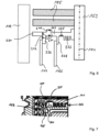
- the Fig. 6 shows an enlarged section of the Fig. 4 to explain the pump blades 230 provided on the outer circumference of the rotor hub 161.
- the rotor shaft 153 of the rotor can be seen, which supports the rotor hub 161, to which the two concentric Holweck rotor sleeves 163, 165 are fastened, which can preferably be made of a CFRP material.
- the Holweck stator sleeves 167, 169 are not shown here for the sake of clarity.
- the rotor hub 161 has a plurality of pump blades 230 along its outer circumference, which are evenly spaced from one another in the circumferential direction. Between these pump blades 230, material can be removed from the outer circumference of the rotor hub 161 in a balancing region 234 by means of laser ablation in order to compensate for any imbalances in the rotor.
- the pump blades 230 can be spaced from one another in the circumferential direction without overlapping. This offers the possibility of locating the balancing region 234 in the non-overlapping region between two adjacent pump blades and thus performing the material removal precisely where the pump blades 230 do not overlap in the circumferential direction.
- the balancing region 234 can also be located between the two Holweck rotor sleeves 163, 165.
- the rotor hub 161 carries the two concentric Holweck rotor sleeves 163, 165. Specifically, the rotor hub 161 forms two annular retaining webs 236, 238, each of which carries a Holweck rotor sleeve 163, 165. As the Fig. 6 can be easily removed, the radially outermost retaining web 236 has a radially outer exposed annular surface 242 on which the rotor or the rotor hub 161 can be balanced, as can be seen from the balancing area 234 shown.
- the rotor hub 161 forms, on the side of the rotor hub 161 opposite the Holweck rotor sleeves 163, 165, a balancing ring 240 which is concentric with the Holweck rotor sleeves 163, 165 and on which a balancing area 234 is located.
- the Fig. 7 shows an enlarged section of the Fig. 4 . It includes, like the Fig. 6 the same area near the labyrinth seal 223.
- the rotor hub 161 has a Fig. 6 recognizable surface section 225, which has undergone a surface treatment to locally increase the emissivity. In the present embodiment, it is arranged radially between the labyrinth seal 223 and the Holweck rotor sleeve 165.
- the surface section 225 may have been treated with at least one of the methods described above and/or may have a coating.
- the coating if provided—may itself have an emissivity-enhancing effect and/or protect a roughening or structuring of the section 225.
- the measurement of thermal radiation was carried out by a Fig. 7 visible infrared sensor 227, but also which is arranged on the cap-like wall 221. In the Fig. 6 There was no representation of the infrared sensor 227, although it is also present there.
- Section 225 is a flat, annular surface area extending in a plane substantially perpendicular to a rotation axis 151 of rotor 149.
- sensor 227 statically arranged with wall 221, continuously receives a portion of the thermal radiation emitted by section 225, allowing continuous temperature measurement. In a thermal equilibrium state, the measured signal should exhibit only minor fluctuations.
- the Section 225 may comprise separate subsections which are evenly distributed, in particular in the circumferential direction, in order to minimise the imbalance generated by them.
- the section 225 is arranged downstream of the pumping stage formed by the rotor disks 155 and stator disks 157 in the pumping direction in order to minimize the effects of any outgassing that could occur due to the surface treatment.
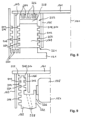
- the Fig. 8 shows an enlarged section of the Fig. 4 in particular to explain the first aspect of the present invention, according to which the outer rotor sleeve 163 has a significantly larger diameter than the inner rotor sleeve 165, which according to the invention makes it possible to provide a significantly thicker Holweck stator sleeve 169 between the two rotor sleeves 163, 165.
- the radially outer Holweck rotor sleeve 163 has a diameter which is at least 30%, preferably at least 35%, larger than the diameter of the radially inner Holweck rotor sleeve 165.
- a Holweck stator sleeve 169 between the two rotor sleeves 163, 165 which has a significantly greater core wall thickness than is the case with conventional Holweck pump stages of the This is the case.
- the stator sleeve is usually a relatively delicate component, the core wall thickness of which is not much greater than the wall thickness of the rotor sleeves, see for example the Fig. 3 and 4 .
- the diameter of the radially outer rotor sleeve 163 is now selected to be significantly larger than the diameter of the radially inner rotor sleeve 165, a stator sleeve 169 with a significantly greater core wall thickness can now be used between the two rotor sleeves 163, 165, which is greater than 5 mm, preferably greater than 6 mm and particularly preferably greater than 7 mm.
- the core wall thickness which for the sake of simplicity is also referred to here as the wall thickness, is measured from the groove base 302 of the external thread 304 to the groove base 302 of the internal thread 308 and thus represents the thickness of the stator sleeve 169 less the height of the thread lands 306, 310 of the external thread 304 and the internal thread 308. Due to the significantly thicker design of the stator sleeve 169, it has a lower thermal resistance, so that hardly any heat builds up at the free end 322 of the stator sleeve 169, since this can be continuously dissipated in the direction of the housing base or the stationary housing section 121.
- a plurality of concentric annular webs 324 are formed, which are nested with corresponding annular webs 326 extending axially from the rotor hub 161.
- the nested annular webs 324, 326 act as a kind of heat exchanger, via which heat can be dissipated from the rotor hub 161 to the stator sleeve 169 and from there to the stationary housing section 121 in the manner explained above.
- stator sleeve 169 is penetrated in the radial direction near its free end 322 by a plurality of gas flow bores 328 through which the process gas can flow in the desired manner from the outer Holweck gap or from the external thread 304 into the inner Holweck gap or into the internal thread 308.
- a plurality of mutually concentric annular grooves 330 are formed in the housing lower part 121. These are located in the embodiment of the Fig. 8 in the lower part 121 radially outside the Holweck stator sleeve 169, whereby additionally or alternatively it can be provided that corresponding annular grooves are also located radially inside the Holweck stator sleeve 169 in the lower part 121 and thus in continuation of the inner rotor sleeve 165.
- annular grooves 330 in the lower part 121 act as cooling fins, which cool the process gas flowing over them in the desired manner, so that friction-related heating of the stator sleeve 169 in the region of the free end 322 thereof cannot even occur.
- corresponding annular grooves 330 can be provided in the lower housing part 121 of the pump 111.
- the inner Holweck rotor sleeve 165 has a significantly shorter axial extent than the radially outer Holweck rotor sleeve 163.
- the axial extent of the inner Holweck rotor sleeve 165 is only approximately 45% to 55% of the axial extent of the radially outer Holweck rotor sleeve 163.
- the stator sleeve 169 is composed of a base ring portion 332, which is attached to the housing lower part 121, and a collar ring portion 434 extending axially from the base ring portion 332.
- the collar ring portion 334 extends from the end face of the base ring portion 332 facing the rotor hub 161 and thus extends into the annular space between the shorter inner rotor sleeve 165 and the longer outer rotor sleeve 163.
- the external thread 304 of the stator sleeve 169 extends axially over the entire common outer surface 354 of the base ring portion 332 and the collar portion 334, whereas the internal thread 308 is provided only over the axial extent of the collar portion 334 on its inner side.
- the motor stator 217 of the electric motor 125 driving the rotor shaft 153 can be attached directly to the annular inner surface 336 of the base ring section 332.
- the base ring section 332 is axially Direction is penetrated by several gas flow holes 338, which are preferably present in the same number as the threads of the internal thread. As shown, these can be aligned obliquely to the rotation axis 151 and thus also extend partly in the radial direction. Likewise, the gas flow holes 338 can also extend at least partly in the circumferential direction, even if this is not shown in the illustration of the Fig. 9 is not recognizable.
- the previously described temperature problem which results in undesirably strong heating of the stator sleeve 169 in the area of its free end 322, is due, among other things, to the undesirable swirling of the process gas as it flows from the external thread 304 over the free end 322 into the internal thread 308.
- This is particularly the case because, in conventional Holweck pump stages, there is no specific assignment of the thread grooves of the external thread 304 to the thread grooves of the internal thread 308. In other words, this means that a gas flowing out of a thread groove of the external thread 304 is distributed between two or more thread grooves of the internal thread 304.
- the invention proposes for the first time to align the external thread 304 and the internal thread 308 rotationally relative to one another in the circumferential direction in such a way that process gas flowing out of a thread groove of the external thread 304, after flowing around the free end 322, flows as far as possible only into a single thread groove of the internal thread 308.
- the end faces 304 which form the thread webs 306 of the external thread 304 at the free end 322 of the Holweck stator sleeve 169, have an offset d in the circumferential direction compared to the end faces 344, which form the threaded webs 310 of the internal thread 308 at the free end 322 of the stator sleeve 169, see the Fig. 10 .
- process gas flowing out of a thread groove of the external thread 304 flows diagonally over the free end 322 of the stator sleeve 169 in a targeted manner, in order to then flow into exactly one thread groove of the internal thread 308 on the inside of the stator sleeve 169, which of course requires that the number of thread lands 306 of the external thread 304 is the same as the number of thread lands 310 of the internal thread 308.
- the end faces 344 of the threaded webs 310 of the internal thread 308 enclose an acute angle ⁇ with the plane in which the free end 322 of the Holweck stator sleeve 169 lies, which angle is preferably between 10 and 40°, in particular preferably between 20 and 30°.
- the core wall thickness decreases towards the free end 322 of the Holweck stator sleeve 169, since this corresponds to an increase in the height of the threaded webs 306, 310 at the free end 322 of the stator sleeve 169.
- the inflow cross-section into the threaded grooves of the internal thread 308 is increased, which facilitates the flow of the process gas into the threaded grooves of the internal thread 308.
- the wall thickness can taper towards the free end 322 in the sense of a chamfer 346, which preferably formed only on the inside of the free end 322 of the stator sleeve 169.
- the chamfer 346 has a straight or linear contour; however, as shown, the chamfer 346 can also be provided on the outside and have a convex, round, or parabolic contour, as shown in dashed lines.
- the chamfer 346 extends only over the first turn of the internal thread 308; however, as shown in dash-dotted lines, the chamfer 346 can also extend over an area defined by the two turns of the internal thread 308 closest to the free end 322.
- a flow profile 356 with a concave cross-section is provided on the rotor hub 161 of the Holweck rotor between the two Holweck rotor sleeves 163, 165, which concentrically surrounds the rotor shaft 153.
- the flow profile 356 is a part that can be handled separately from the hub 161 and is attached to the hub 161. This flow profile 356 also ensures a turbulence-free flow around the free end 322 of the Holweck stator sleeve 169, which in turn has a positive effect on the pump's suction capacity and its power consumption.
- the Holweck stator sleeve 169 has at its free end 322 a plurality of circumferentially evenly spaced spaced-apart flow contours 348, each flow contour 348 defining a defined flow path between a thread groove of the external thread 304 and a single thread groove of the internal thread 308, as illustrated by the flow arrow S.
- the flow contours 348 can be guide vanes 350 formed on the free end 322 of the stator sleeve 169, each extending between an end face 340 of the external thread 304 and an end face 344 of the internal thread 308. Contrary to the embodiment shown, these can be curved, in particular concave or convex, in order to guide the process gas over the free end 322 of the stator sleeve 169 with as little turbulence as possible.
Landscapes
- Engineering & Computer Science (AREA)
- Mechanical Engineering (AREA)
- General Engineering & Computer Science (AREA)
- Non-Positive Displacement Air Blowers (AREA)
Priority Applications (1)
| Application Number | Priority Date | Filing Date | Title |
|---|---|---|---|
| EP25164818.4A EP4553321A1 (fr) | 2025-03-19 | 2025-03-19 | Pompe à vide à haute puissance et densité |
Applications Claiming Priority (1)
| Application Number | Priority Date | Filing Date | Title |
|---|---|---|---|
| EP25164818.4A EP4553321A1 (fr) | 2025-03-19 | 2025-03-19 | Pompe à vide à haute puissance et densité |
Publications (1)
| Publication Number | Publication Date |
|---|---|
| EP4553321A1 true EP4553321A1 (fr) | 2025-05-14 |
Family
ID=94971894
Family Applications (1)
| Application Number | Title | Priority Date | Filing Date |
|---|---|---|---|
| EP25164818.4A Pending EP4553321A1 (fr) | 2025-03-19 | 2025-03-19 | Pompe à vide à haute puissance et densité |
Country Status (1)
| Country | Link |
|---|---|
| EP (1) | EP4553321A1 (fr) |
Citations (4)
| Publication number | Priority date | Publication date | Assignee | Title |
|---|---|---|---|---|
| US6599084B1 (en) * | 1999-04-03 | 2003-07-29 | Leybold Vakuum Gmbh | Rotor fixture for a friction vacuum pump |
| EP2631488A2 (fr) * | 2012-02-23 | 2013-08-28 | Pfeiffer Vacuum Gmbh | Pompe à vide |
| EP3139044B1 (fr) * | 2015-09-04 | 2020-04-22 | Pfeiffer Vacuum Gmbh | Procédé d'équilibrage d'un rotor d'une pompe à vide ou d'un rotor d'une unité de rotation pour une pompe à vide |
| DE112020001075T5 (de) * | 2019-03-05 | 2022-01-05 | Pfeiffer Vacuum Sas | Turbomolekularvakuumpumpe und Spülverfahren |
-
2025
- 2025-03-19 EP EP25164818.4A patent/EP4553321A1/fr active Pending
Patent Citations (4)
| Publication number | Priority date | Publication date | Assignee | Title |
|---|---|---|---|---|
| US6599084B1 (en) * | 1999-04-03 | 2003-07-29 | Leybold Vakuum Gmbh | Rotor fixture for a friction vacuum pump |
| EP2631488A2 (fr) * | 2012-02-23 | 2013-08-28 | Pfeiffer Vacuum Gmbh | Pompe à vide |
| EP3139044B1 (fr) * | 2015-09-04 | 2020-04-22 | Pfeiffer Vacuum Gmbh | Procédé d'équilibrage d'un rotor d'une pompe à vide ou d'un rotor d'une unité de rotation pour une pompe à vide |
| DE112020001075T5 (de) * | 2019-03-05 | 2022-01-05 | Pfeiffer Vacuum Sas | Turbomolekularvakuumpumpe und Spülverfahren |
Similar Documents
| Publication | Publication Date | Title |
|---|---|---|
| EP3657021B1 (fr) | Pompe à vide | |
| EP3557073A1 (fr) | Pompe à vide | |
| DE102013214662A1 (de) | Vakuumpumpe | |
| DE102013200655B4 (de) | Kombiniertes Radial-Axiallager und Nassläuferpumpe | |
| EP3112687B1 (fr) | Détection de la circulation d'un gaz auxiliaire qui est injecté dans une pompe à vide | |
| EP3926175B1 (fr) | Pompe à vide dotée d'un palier à roulement | |
| EP3034882B1 (fr) | Pompe à vide | |
| EP3438460A1 (fr) | Pompe à vide | |
| EP3318763B1 (fr) | Étanchéité au vide, étanchéité double, système à vide et pompe à vide | |
| EP4194700B1 (fr) | Pompe à vide avec étage de pompe de holweck à géométrie de holweck variable | |
| EP3135932B2 (fr) | Pompe a vide et palier a aimant permanent | |
| EP4212730A1 (fr) | Pompe à vide avec étage de pompage de holward optimisé pour compenser la perte de performance liée à la température | |
| EP4549740A2 (fr) | Pompe à vide optimisée en termes de technique d'écoulement et de température | |
| EP4144994B1 (fr) | Dispositif et procédé d'évaluation d'un palier magnétique | |
| EP4206474B1 (fr) | Pompe à vide | |
| EP3557072A1 (fr) | Surveillance d'un dispositif de palier d'une pompe à vide | |
| EP3907406B1 (fr) | Pompe à vide | |
| EP4474654B1 (fr) | Pompe à vide turbomoléculaire | |
| EP4151860B1 (fr) | Pompe à vide | |
| EP4293232B1 (fr) | Pompe turbomoléculaire | |
| EP3575610B1 (fr) | Pompe à vide avec réservoir de lubrifiant | |
| EP4155549B1 (fr) | Pompe à vide à capacité d'aspiration améliorée de l'étage de pompage holweck | |
| EP4443007A1 (fr) | Pompe turbomoléculaire | |
| EP3633204A1 (fr) | Pompe à vide | |
| WO2003067032A1 (fr) | Moteur a air comprime |
Legal Events
| Date | Code | Title | Description |
|---|---|---|---|
| PUAI | Public reference made under article 153(3) epc to a published international application that has entered the european phase |
Free format text: ORIGINAL CODE: 0009012 |
|
| STAA | Information on the status of an ep patent application or granted ep patent |
Free format text: STATUS: THE APPLICATION HAS BEEN PUBLISHED |
|
| AK | Designated contracting states |
Kind code of ref document: A1 Designated state(s): AL AT BE BG CH CY CZ DE DK EE ES FI FR GB GR HR HU IE IS IT LI LT LU LV MC ME MK MT NL NO PL PT RO RS SE SI SK SM TR |
|
| STAA | Information on the status of an ep patent application or granted ep patent |
Free format text: STATUS: REQUEST FOR EXAMINATION WAS MADE |
|
| 17P | Request for examination filed |
Effective date: 20250429 |