EP4554012A2 - Borne de connexion de conducteur, utilisation et procédé de montage d'une borne de connexion de conducteur - Google Patents
Borne de connexion de conducteur, utilisation et procédé de montage d'une borne de connexion de conducteur Download PDFInfo
- Publication number
- EP4554012A2 EP4554012A2 EP25157844.9A EP25157844A EP4554012A2 EP 4554012 A2 EP4554012 A2 EP 4554012A2 EP 25157844 A EP25157844 A EP 25157844A EP 4554012 A2 EP4554012 A2 EP 4554012A2
- Authority
- EP
- European Patent Office
- Prior art keywords
- housing
- housing part
- conductor
- contact insert
- connection terminal
- Prior art date
- Legal status (The legal status is an assumption and is not a legal conclusion. Google has not performed a legal analysis and makes no representation as to the accuracy of the status listed.)
- Pending
Links
Images


Classifications
-
- H—ELECTRICITY
- H01—ELECTRIC ELEMENTS
- H01R—ELECTRICALLY-CONDUCTIVE CONNECTIONS; STRUCTURAL ASSOCIATIONS OF A PLURALITY OF MUTUALLY-INSULATED ELECTRICAL CONNECTING ELEMENTS; COUPLING DEVICES; CURRENT COLLECTORS
- H01R13/00—Details of coupling devices of the kinds covered by groups H01R12/70 or H01R24/00 - H01R33/00
- H01R13/46—Bases; Cases
- H01R13/502—Bases; Cases composed of different pieces
-
- H—ELECTRICITY
- H01—ELECTRIC ELEMENTS
- H01R—ELECTRICALLY-CONDUCTIVE CONNECTIONS; STRUCTURAL ASSOCIATIONS OF A PLURALITY OF MUTUALLY-INSULATED ELECTRICAL CONNECTING ELEMENTS; COUPLING DEVICES; CURRENT COLLECTORS
- H01R4/00—Electrically-conductive connections between two or more conductive members in direct contact, i.e. touching one another; Means for effecting or maintaining such contact; Electrically-conductive connections having two or more spaced connecting locations for conductors and using contact members penetrating insulation
- H01R4/28—Clamped connections, spring connections
- H01R4/48—Clamped connections, spring connections utilising a spring, clip, or other resilient member
- H01R4/4809—Clamped connections, spring connections utilising a spring, clip, or other resilient member using a leaf spring to bias the conductor toward the busbar
- H01R4/484—Spring housing details
-
- H—ELECTRICITY
- H01—ELECTRIC ELEMENTS
- H01R—ELECTRICALLY-CONDUCTIVE CONNECTIONS; STRUCTURAL ASSOCIATIONS OF A PLURALITY OF MUTUALLY-INSULATED ELECTRICAL CONNECTING ELEMENTS; COUPLING DEVICES; CURRENT COLLECTORS
- H01R4/00—Electrically-conductive connections between two or more conductive members in direct contact, i.e. touching one another; Means for effecting or maintaining such contact; Electrically-conductive connections having two or more spaced connecting locations for conductors and using contact members penetrating insulation
- H01R4/28—Clamped connections, spring connections
- H01R4/48—Clamped connections, spring connections utilising a spring, clip, or other resilient member
- H01R4/4809—Clamped connections, spring connections utilising a spring, clip, or other resilient member using a leaf spring to bias the conductor toward the busbar
- H01R4/48185—Clamped connections, spring connections utilising a spring, clip, or other resilient member using a leaf spring to bias the conductor toward the busbar adapted for axial insertion of a wire end
- H01R4/4819—Clamped connections, spring connections utilising a spring, clip, or other resilient member using a leaf spring to bias the conductor toward the busbar adapted for axial insertion of a wire end the spring shape allowing insertion of the conductor end when the spring is unbiased
- H01R4/4821—Single-blade spring
-
- H—ELECTRICITY
- H01—ELECTRIC ELEMENTS
- H01R—ELECTRICALLY-CONDUCTIVE CONNECTIONS; STRUCTURAL ASSOCIATIONS OF A PLURALITY OF MUTUALLY-INSULATED ELECTRICAL CONNECTING ELEMENTS; COUPLING DEVICES; CURRENT COLLECTORS
- H01R4/00—Electrically-conductive connections between two or more conductive members in direct contact, i.e. touching one another; Means for effecting or maintaining such contact; Electrically-conductive connections having two or more spaced connecting locations for conductors and using contact members penetrating insulation
- H01R4/28—Clamped connections, spring connections
- H01R4/48—Clamped connections, spring connections utilising a spring, clip, or other resilient member
- H01R4/4809—Clamped connections, spring connections utilising a spring, clip, or other resilient member using a leaf spring to bias the conductor toward the busbar
- H01R4/4846—Busbar details
- H01R4/485—Single busbar common to multiple springs
Definitions
- the invention relates to a conductor connection terminal, the use of a conductor connection terminal and a method for assembling a conductor connection terminal.
- Conductor connection terminals can, in particular, be terminals that are used for the detachable connection or connection of electrical conductors and, when clamped, can ensure electrical contact of the conductor by mechanically securing the connected conductor.
- Conductor connection terminals can be spring-loaded terminals, which are also called plug-in terminals, spring terminals, cage clamp terminals, cage clamps, or spring-loaded terminals.
- Conductor connection terminals are known in which a contact insert can be inserted into a laterally open recess of a housing and this recess can be closed with a cover.
- the object of the invention is to provide an improved conductor connection terminal with a simplified structure, easier assembly and higher operational reliability.
- the conductor connection terminal has a contact insert having a busbar and a clamping spring, and a housing having a first housing part and a second housing part, which at least partially encloses the contact insert, wherein the first housing part has a first housing wall with a receiving structure for receiving the contact insert and the second housing part has a plurality of further housing walls for covering the contact insert received by the first housing part.
- the housing at least partially encloses the contact insert.
- the housing can completely enclose or surround the contact insert.
- the housing protects the contact insert, for example, from environmental conditions and from accidental or unauthorized access to the contact insert by a person.
- the housing enables electrical insulation of the contact insert from the environment and can therefore be made of an insulating material such as a plastic.
- the housing is constructed in at least two parts, with a first and a second housing part, and can be assembled with the first, the second and optionally further housing parts to form a complete housing.
- the first and second housing parts can, for example, be assembled along a connecting line. Housing walls can merge flush into one another at the connecting line.
- the first housing part has a receiving structure for receiving the contact insert.
- the receiving structure can, for example, be a receiving shape formed integrally with the first housing part, which can, for example, be designed as an attachment or insert structure.
- the receiving structure can, for example, have material projections, support elements, negative contours of the contact insert, fastening structures such as clip receptacles, or other means for, in particular, a releasable, positive-locking and/or non-positive connection of the first housing part to the contact insert.
- the receiving structure can, for example, have a spring carrier.
- the receiving structure can enable the received contact insert to be fixed by reducing selected degrees of freedom of movement.
- the receiving structure can be defined by a predetermined attachment or insert structure. simplify the positioning and assembly of the contact insert on the first housing part.
- the first housing part can also be referred to as the base or main housing.
- the second housing part has multiple housing walls.
- the main extensions of the housing walls can run in different planes.
- adjacent housing walls can be substantially perpendicular to one another.
- housing walls of the second housing part can lie opposite one another and run substantially parallel to one another.
- Some or all of the housing walls can be solid-surface.
- Some or all of the housing walls can have openings.
- the second housing part can also be referred to as a cover housing. In a typical assembly process for a housing with a base housing and a cover housing, the cover housing is usually placed finally onto the base housing, which is why the second housing part can be described here as a cover housing.
- the second housing part differs from a simple housing cover, which usually has only one housing wall, as is known from the prior art, by having multiple housing walls.
- the conductor connection terminal has a simplified design and enables easier installation.
- the receiving structure of the first housing wall of the first housing part is easily accessible and enables quick and secure installation of the contact insert on the first housing part.
- the second housing part can be safely and quickly arranged on the first housing part and connected to it. By covering the contact insert with several housing walls of the second housing part, compliance with the required clearance and creepage distances for the operational reliability of the conductor connection terminal is ensured.
- the receiving structure has at least one frame wall that projects substantially transversely from the first housing wall and, together with the first housing wall, defines a receiving space for the contact insert.
- This provides a housing wall with a receiving structure that defines a defined
- the mounting space defines and visualizes the intended mounting location for the contact insert.
- the frame wall can reduce the degree of freedom of movement of the contact insert.
- the limited mounting space makes mounting the conductor connection terminal safer and easier.
- the frame wall can also provide improved mechanical protection and support the electrical insulation of the contact insert.
- the frame wall can be offset below the edge or a terminal edge of the first housing wall to form a recess in order to create a mounting area for a housing wall of the second housing part.
- the frame wall extends along a long side of the contact insert.
- One long side of the contact insert can run essentially parallel to a direction of insertion of an electrical conductor into the conductor connection terminal.
- One end face of the contact insert can run essentially transverse to a direction of insertion of an electrical conductor into the conductor connection terminal.
- the contact insert can, for example, have four long sides and two end faces.
- the assembled housing can also, for example, have four long sides and two end faces.
- a frame wall extends along a bottom side of the contact insert facing the busbar of the contact insert and/or along a top side of the contact insert facing away from the busbar of the contact insert.
- a bottom side and a top side of the contact insert can each correspond to a long side of the contact insert.
- a busbar of the contact insert can be arranged on a bottom side.
- a top side can be a side or long side of the contact insert opposite the bottom side or running substantially parallel to the bottom side.
- the first housing wall can have two frame walls. The frame walls can form a receiving space for the contact insert. limit.
- the receiving space can be delimited by walls on three sides of the receiving space that extend parallel to an insertion direction of an electrical conductor, namely the first housing wall and two frame walls.
- a frame wall running along a top or bottom side of the contact insert supports intuitive assembly of the contact insert.
- a frame wall running along a top and bottom side of the contact insert improves mechanical protection and insulation over the length of the contact insert.
- a receiving space for the contact insert is more precisely defined and delimited.
- the second housing part has at least three housing walls for covering the contact insert and/or the first housing part. This improves the covering function of the second housing part. At least one of the at least three housing walls can run essentially parallel to a long side and/or essentially parallel to an end face of the contact insert. Two of the at least three housing walls can be arranged essentially perpendicular to one another.
- the second housing part can in particular also have at least four or at least five housing walls for covering the contact insert and/or the first housing part.
- the second housing part can, for example, have three housing walls that run essentially parallel to a long side of the contact insert and two that run essentially parallel to an end face of the contact insert.
- At least one housing wall of the second housing part partially or completely covers a frame wall of the first housing part.
- at least one housing wall of the second housing part can cover a frame wall of the first housing part with a degree of coverage of more than 50%, in particular more than 70%, further in particular more than 80%, wherein the degree of coverage is the percentage of the sum of the mutually facing and overlapping surfaces of the housing wall and the frame wall of the sum of the mutually facing total surfaces the housing wall and the frame wall.
- a housing wall of the second housing part and a frame wall of the first housing part can therefore overlap at least partially. With the overlap, there can be mechanical contact between a housing wall and a frame wall, i.e.
- the overlapping frame and housing walls can, for example, extend essentially parallel to one another.
- the housing wall of the second housing part can form the outer wall facing the environment and the frame wall of the first housing part can form the inner wall facing the contact insert.
- the overlap can also be in the form of a clearance fit, transition fit, or interference fit of a housing wall with a frame wall.
- a double wall is formed locally by the first and second housing parts, which improves the mechanical protection and electrical insulation of the conductor connection terminal.
- the intended overlap provides a predetermined assembly arrangement and orientation of the first and second housing parts to each other, thereby simplifying assembly.
- first housing part and the second housing part each have a U-shaped cross-section, whereby in the assembled state of the housing, the U-legs of the second housing part accommodate the U-legs of the first housing part between them, and the U-legs of the first housing part accommodate the contact insert between them.
- the second housing part as the cover housing can have a larger U-shaped cross-section than the first housing part as the base housing, so that the cover housing can be placed or pushed onto the base housing and, in the assembled state of the housing, the cover housing engages over the base housing on several sides. This enables a simple construction of the conductor connection terminal with intuitive and simplified assembly.
- the interlocking U-legs of the first and second housing parts create a positive fit, which enables a secure mechanical connection of the housing parts.
- the contact insert is securely in the The cross-section of the two housing parts is enclosed.
- the second housing part has a housing end wall for covering the end face of the housing.
- the second housing part can have two housing end walls for covering the end face of the housing on two opposite end faces of the housing.
- One housing end wall can extend substantially transversely to a direction of insertion of an electrical conductor into the conductor connection terminal.
- One housing end wall can extend substantially transversely to a long side of the housing.
- One end face of the housing can run substantially parallel to an end face of the contact insert inserted into the housing.
- One end face of the housing can be a housing side through which a conductor inserted into the conductor connection terminal enters the housing.
- One end face of the housing can have a smaller housing surface than a long side of the housing.
- One housing end wall can be a housing wall of the housing or housing part.
- a housing end wall improves the covering function of the second housing part in the end face region of the inserted contact insert.
- the first housing part or base housing can also have one or more housing end walls.
- a housing end wall of the first housing part can at least partially cover or overlap a housing end wall of the second housing part.
- One or more housing end walls can have an opening, for example, a conductor insertion opening.
- the conductor connection terminal is a double terminal for two electrical conductors that can be inserted into the conductor connection terminal in a respective insertion direction.
- the respective insertion directions can, for example, be opposite to each other.
- the contact insert can have two opposing clamping springs and a common busbar for both spring-loaded terminal connections.
- the housing of the conductor connection terminal can, for example, have two opposing housing walls with conductor insertion openings arranged at the front. In further embodiments, it is also conceivable to connect more than two electrical conductors to the conductor connection terminal.
- a partition wall projects transversely from the frame wall and/or from the first housing wall. This can enable or improve the spatial separation of two or more conductor connection spaces for spring-loaded terminal connections.
- the second housing part can have a partition wall receptacle, which is designed, for example, as two spaced-apart, also wall-like material projections, between which the partition wall can be inserted. This increases the stability of the conductor connection terminal and simplifies assembly, since the partition wall receptacle can serve as a guide and orientation for the positioning of the first and second housing parts relative to one another.
- the partition wall and the partition wall receptacle can also be detachably connected to one another by means of a snap-in connection in order to improve the connection between the first and second housing parts.
- a wall-like partition wall receptacle further improves the insulation of the conductor connection spaces from one another.
- One or more frame walls can have a frame recess, which can, for example, run parallel to a housing wall recess of the second housing part and together with it form a grip recess.
- the grip recess can facilitate gripping of the conductor connection terminal or, for example, also visualize the top or bottom of the conductor connection terminal.
- the frame wall has a support block that projects transversely from the frame wall.
- This can, for example, support a contact insert at the front or limit its axial mobility.
- the support block can more precisely define the receiving space for the contact insert.
- the support block can increase the stability of the first housing part.
- the frame wall can also have two or more support blocks projecting transversely from the frame wall.
- the support block(s) can, together with one or more frame walls and the first housing wall of the first housing part, form a receiving structure or an inner housing for the defined reception of the contact insert.
- the support block may have a conductor entry channel area. This improves the guidance of an inserted electrical conductor and simplifies the operation of the conductor terminal.
- the contact insert and/or the housing have a symmetrical design. This further simplifies the design of the conductor connection terminal. Furthermore, assembly is easier because, for example, the contact insert can be inserted into the first housing part in more than one orientation.
- the axis of symmetry can, for example, coincide with a central axis of the contact insert or the housing, which runs through the spatial center of the body of the contact insert or the housing.
- first housing part and the second housing part are locked, caulked, and/or welded together when the housing is assembled. This ensures a secure connection between the first and second housing parts and increases the stability of the conductor connection terminal.
- the first housing part has a first conductor insertion channel section and the second housing part has a second conductor insertion channel section, wherein, in the assembled state of the housing, the first conductor insertion channel section and the second conductor insertion channel section together form a conductor insertion channel for inserting an electrical conductor.
- the joint formation of the conductor insertion channel increases its stability and expansion.
- the assembly of the conductor connection terminal is simplified and intuitive, since when the first and second housing parts are connected to one another, the conductor insertion channel sections are adjacent to one another. are to be arranged.
- the manufacture of the first and second housing parts is simplified if only one conductor entry channel section is provided on each of them, thus, for example, requiring fewer undercuts.
- the first conductor entry channel section can be assigned to the base housing of the conductor connection terminal and the second conductor entry channel section can be assigned to the cover housing of the conductor connection terminal.
- the first conductor entry channel section can form an inner section of the conductor entry channel facing the receiving space or contact insert, and the second conductor entry channel section can form an outer section of the conductor entry channel facing the environment.
- the second conductor entry channel section can have a conductor entry opening accessible from outside the conductor connection terminal.
- first conductor entry channel section and/or the second conductor entry channel section are substantially or predominantly closed on the circumference.
- the first conductor entry channel section and/or the second conductor entry channel section can be circumferentially closed by more than 180°, in particular more than 270°.
- the first conductor entry channel section and/or the second conductor entry channel section can thus have a substantially closed cross-section. This more precisely defines the conductor entry channel and increases the stability of the conductor connection terminal in the conductor entry region. Safe and intuitive insertion of an electrical conductor into the conductor entry channel is possible.
- first conductor entry channel section and the second conductor entry channel section are designed to be substantially closed on the circumference, the area of the first housing part and the second housing part adjacent to the conductor entry channel can be at least partially covered, so that the at least partial cover results in increased stability and better insulation of the contact insert by the housing.
- the first conductor insertion channel section can be arranged behind the second conductor insertion channel section in the conductor insertion direction. of the electrical conductor, it first passes through the second conductor entry channel section and then through the first conductor entry channel section.
- the housing has a conductor insertion opening for inserting an electrical conductor, which is formed on the second conductor channel section.
- the conductor insertion opening defines the insertion region of the electrical conductor into the housing and is therefore visible from the outside.
- the conductor insertion opening can, for example, form a region of the largest cross-section of the conductor insertion channel in the case of a conductor insertion channel that tapers in the conductor insertion direction.
- a housing wall, in particular a housing end wall of the second housing part or cover housing, can enclose or frame the conductor insertion opening.
- the conductor insertion opening can be designed as an opening in a housing wall or housing end wall of the second housing part or cover housing.
- the problem is also solved by using a conductor connection terminal with one of the aforementioned features as a repair terminal for connecting sections of a severed electrical conductor or two free conductor ends. Due to the simple design, simplified assembly, and high insulating capacity of the conductor connection terminal, it is particularly suitable for use in repair work.
- the object is also achieved by a method for assembling a conductor connection terminal with a contact insert having a busbar and a clamping spring, and with a housing having a first housing part and a second housing part, which at least partially encloses the contact insert, in which the contact insert is inserted into the first housing part and then the second housing part having a plurality of housing walls is arranged on the first housing part and connected to it.
- This provides a method which enables a particularly simple, quick and intuitive assembly of a conductor connection terminal.
- By covering the contact insert by means of a plurality of housing walls of the second housing part, compliance with the required Air gaps and creepage distances are ensured for the operational reliability of the conductor connection terminal.
- the first housing part can form a base housing and the second housing part can form a cover housing.
- the contact insert can in particular be inserted into a receiving space of the first housing part formed by a first housing wall and a frame wall protruding transversely from the first housing wall.
- a common conductor entry channel can in particular be formed from a first conductor entry channel section of the first housing part and a second conductor entry channel section of the second housing part.
- the contact insert can be formed in an upstream method step by assembling at least one busbar and at least one clamping spring. The contact insert can in particular be pre-assembled.
- the insertion direction of the contact insert into the first housing part is transverse to the longitudinal direction of the contact insert.
- the longitudinal direction of the contact insert can run essentially parallel to a conductor insertion direction.
- the contact insert is not inserted or pushed into a housing with one end face first in a conductor insertion direction or opposite thereto, but is moved transversely to this direction towards the first housing part and placed, for example, on a receiving structure and/or in a receiving space of the first housing part.
- This enables simple and quick assembly of the conductor connection terminal.
- the arrangement of the second housing part on the first housing part takes place in a placement direction that in particular corresponds to the insertion direction of the contact insert into the first housing part or runs parallel to this.
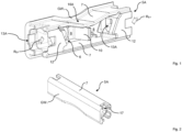
- Figure 1 shows a front view of a first housing part 5A for a device shown for example in the Figures 6 to 10 shown, designed as a double terminal conductor connection terminal 1.
- the first housing part 5A can be connected to a, for example, Figures 3 to 5 shown second housing part 5B to form a housing 5 of the conductor connection terminal 1.
- the housing 5 of the conductor connection terminal 1 is constructed in two parts from the first housing part 5A and the second housing part 5B. It is fundamentally conceivable to assemble the housing 5 of the conductor connection terminal 1 from more than two housing parts.
- the housing 5 of the conductor connection terminal 1 is set up, for example, in the Figures 6 , 7 and 11 to at least partially enclose the contact insert 2 shown with a busbar 3 and one or more clamping springs 4 in order to protect the contact insert 2 from ambient conditions and to provide electrical insulation of the contact insert 2 from the environment.
- the first housing part 5A has a first housing wall GW 1 with a receiving structure 6 for receiving the contact insert 2.
- the receiving structure 6 is formed by several structural elements, such as frame walls 7 (explained below), a partition wall 10, spring supports, and support blocks 12. However, it is also conceivable to provide more or fewer structural elements to form the receiving structure 6.
- Two frame walls 7 protrude substantially vertically from the first housing wall GW 1 and, together with the first housing wall GW 1, define a receiving space 8 for the contact insert 2.
- the frame walls 7 extend along the long sides of the contact insert 2 to be inserted.
- one frame wall 7 extends along a line facing the busbar 3 of the contact insert 2 and in Figure 11 shown underside Ku of the contact insert 2 and along a side facing away from the busbar of the contact insert 2, in Figure 11 shown top side Ko of the contact insert 2.
- One of the two frame walls 7 shown has a frame recess 16A, which is, for example, parallel to a housing wall recess 16B ( Fig. 3 ) of the second housing part 5B and together with it forms a grip recess.
- the grip recess can facilitate gripping of the conductor connection terminal 1 and, in the illustrated embodiments, visualize an upper side of the conductor connection terminal 1 facing away from the busbar 3 of the contact insert 2.
- a partition wall 10 projects essentially vertically from the first housing wall GW 1 and from one of the frame walls 7. This partition wall serves, among other things, to spatially separate and electrically insulate two adjacent connection spaces for electrical conductors.
- the partition wall 10 defines a central region of the first housing part, from which, on the left and right, A spring-loaded terminal connection for an electrical conductor can be provided. For this purpose, an electrical conductor can be inserted into the conductor connection terminal 1 in one insertion direction R EF .
- Support blocks 12 protrude from the frame walls 7, which further delimit the receiving space 8 for the contact insert 2 and reduce or prevent a translational mobility of the contact insert 2 in the same or opposite direction to the insertion direction R EF .
- a first conductor insertion channel section 13A is formed on the first housing part 5A for each side of the double terminal, which, in the assembled state of the housing 5, together with a Figure 3 shown second conductor insertion channel section 13B of the second housing part 5B forms a conductor insertion channel 13.
- the first housing part 5A is shown in a rear view. It can be seen, for example, how one of the frame walls 7 protrudes essentially perpendicularly from the first housing wall GW 1.
- the frame wall 7 is offset slightly inward, i.e., it does not have a surface flush with an end edge of the first housing wall GW 1.
- the shoulder 17 formed between the frame wall 7 and the end edge of the first housing wall GW 1 forms a receiving area for a housing wall of the second housing part 5B, for example, the fourth housing wall GW 4 .
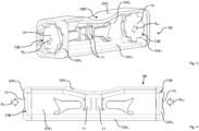
- FIG. 3 shows a front view of a second housing part 5B for the conductor connection terminal 1.
- the second housing part 5B has several housing walls, namely in the embodiment shown a second housing wall GW 2 , a third housing wall GW 3 , a fourth housing wall GW 4 and two housing end walls GWs.
- the housing walls GW 2 , GW 3 , GW 4 and GWs serve to at least partially cover the contact insert 2 of the conductor connection terminal 1 and, supplemented by the first housing wall GW 1 of the first housing part 5A, form the housing 5 of the conductor connection terminal 1 in the assembled state of the first and second housing parts 5A and 5B.
- the second housing part 5B acts as Cover housing and is designed to be placed onto the first housing part 5A after a contact insert 2 has been installed in the first housing part 5A.
- the housing walls GW 1 , GW 2 , GW 3 , GW 4 can be assigned to the long sides of the conductor connection terminal 1 or the housing 5 or the contact insert 2, while the housing end walls GWs can be assigned to the end sides of the conductor connection terminal 1 or the housing 5 or the contact insert 2.
- the housing end walls GWs of the second housing part 5B each have an opening which forms a conductor insertion opening 14 and a second conductor insertion channel section 13B.
- An electrical conductor in the exemplary embodiment shown an electrical conductor from opposite end faces of the second housing part 5B, can be inserted into the housing 5 in a conductor insertion direction R EF into the conductor insertion opening 14 and the adjoining second conductor insertion channel section 13B.
- the second housing part 5B has a partition wall receptacle 11 in the form of two spaced, wall-like material projections, between which the partition wall 10 of the first housing part 5A can be inserted.
- the second housing part 5B has a housing wall recess 16B, which, in the assembled state of the housing 5, covers a frame recess 16A of the first housing part 5A and, together with the frame recess, forms a grip recess.
- the Figures 4 and 5 show the second housing part 5B in a further front view and a bottom view for further illustration.
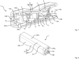
- Figure 6 shows the conductor connection terminal 1 in an assembled state, i.e. with an inserted contact insert 2 and the housing 5 enclosing the contact insert 2, formed from the first housing part 5A and the second housing part 5B.
- the contact insert 2 can be seen with a busbar 3 and two clamping springs 4 for two spring-loaded terminal connections of two electrical conductors (not shown) that can be inserted in the insertion direction R EF into the conductor connection terminal 1.
- the third housing wall GW 3 and the fourth housing wall GW 4 of the second housing part 5B enclose the frame walls 7 of the first housing part 5A. overlap, so that in each case a double wall is present which increases the insulation and the stability of the conductor connection terminal 1.
- first conductor insertion channel section 13A of the first housing part 5A and the second conductor insertion channel section 13B of the second housing part 5B together form a conductor insertion channel 13 for inserting an electrical conductor, starting with the conductor insertion opening 14 of the second housing part 5B.
- the support blocks 12 additionally have a conductor insertion channel region 18 for continuation of the conductor insertion channel 13. It is also clear how the receiving structure 6 of the conductor connection terminal 1 with several structural elements such as spring supports, the partition wall receptacle 11, the frame walls 7 and the support blocks 12 define a delimited receiving space for the contact insert 2, so that the latter is held securely in the housing 5 and assembly is facilitated.
- the partition 10 extends between the material projections of the partition receptacle 11, which also facilitates the positioning and fixing of the first housing part 5A and the second housing part 5B to one another.
- a symmetrical structure of the conductor connection terminal 1 is also clearly visible, with a symmetry axis (not shown) running perpendicular to the insertion direction R EF through the partition 10.
- the conductor connection terminal 1 has a simplified design and enables easier assembly of the conductor connection terminal 1.
- the receiving structure 6 of the first housing wall GW 1 of the first housing part 5A is easily accessible and enables quick and secure assembly of the contact insert 2 on the first housing part 5A.
- the second housing part 5B can be safely and quickly arranged on the first housing part 5A and connected to it.
- Figure 7 shows the representation of the conductor connection terminal 1 from Figure 6 for further illustration in a perspective view.
- the longitudinal direction R LE of the contact insert 2 is marked by a double arrow.
- the contact insert 2 is inserted into the first housing part 5A transversely to this longitudinal extension direction R LE in an insertion direction R ES .
- Figure 8 shows a perspective rear view of the conductor connection terminal 1 with the assembled housing 5. It can be seen that the housing parts 5A, 5B are assembled along a connecting line 15. At the connecting line 15, the first housing wall GW 1 of the first housing part 5A and the fourth housing wall GW 4 of the second housing part 5B merge flush into one another. The situation is similar on the opposite side at the transition from the first housing wall GW 1 to the third housing wall GW 3.
- the first housing part 5A and the second housing part 5B can, for example, also be latched, caulked and/or welded to one another in the assembled state of the housing 5.
- Figure 9 shows a sectional side view of the conductor connection terminal 1 with inserted contact insert 2 and housing 5 assembled from the housing parts 5A, 5B.
- the first housing part 5A and the second housing part 5B in the embodiment shown each have a U-shaped cross section, wherein in the assembled state of the housing 5 the U-legs 9B of the second housing part 5B accommodate the U-legs 9A of the first housing part 5A between them and the U-legs 9A of the first housing part 5A accommodate the contact insert 2 between them.
- Figure 10 shows the sectioned view of the conductor connection terminal 1 from Figure 9 for additional illustration in a perspective view.
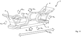
- Figure 11 shows a pre-assembled contact insert 2 for the conductor connection terminal 1 in a perspective view.
- the contact insert 2 has a busbar 3, on each end of which a clamping spring 4 is placed to form a spring-loaded terminal connection with an electrical conductor.
- the contact insert 2 has two end faces Ks, via which the respective electrical conductor is brought closer and inserted into the contact insert 2.
- the contact insert 2 also has a 3 and an upper side Ko opposite the lower side Ku.
- the contact insert 2 has a cover side K D facing the cover housing 5B and a housing side K G facing the base housing 5A, which can also be interchanged if the contact insert 2 is symmetrical.
- the lower side Ku, the upper side Ko, the cover side K D and the housing side K G of the contact insert 2 can be regarded as longitudinal sides of the contact insert 2.
- the contact insert 2 has a longitudinal extension in a longitudinal extension direction R LE that is parallel to an insertion direction of the electrical conductor.
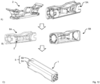
- Figure 12 shows a method for assembling a conductor connection terminal 1 from a contact insert 2, which has a busbar 3 and one or here two clamping springs 4, a first housing part 5A and a second housing part 5B.
- a contact insert 2 is inserted transversely to its longitudinal direction of extension into a first housing part 5A.
- the contact insert 2 can be pre-assembled or can be joined in an upstream preparation step from the busbar 3 and the clamping spring 4 or the clamping springs 4.
- the housing part 5B which has a plurality of housing walls, is arranged, for example placed, on the first housing part 5A.
- the direction in which the second housing part 5B is placed on the first housing part 5A corresponds in particular to the direction in which the contact insert 2 is inserted into the first housing part 5A.
- the first housing part 5A is connected to the second housing part 5B, for example by locking, caulking or welding.
Landscapes
- Connector Housings Or Holding Contact Members (AREA)
- Multi-Conductor Connections (AREA)
Applications Claiming Priority (3)
| Application Number | Priority Date | Filing Date | Title |
|---|---|---|---|
| DE102020120150.8A DE102020120150A1 (de) | 2020-07-30 | 2020-07-30 | Leiteranschlussklemme, Verwendung und Verfahren zur Montage einer Leiteranschlussklemme |
| PCT/EP2021/070864 WO2022023272A1 (fr) | 2020-07-30 | 2021-07-26 | Borne de connexion de conducteur, utilisation de celle-ci, et procédé de montage d'une borne de connexion de conducteur |
| EP21749200.8A EP4189779B1 (fr) | 2020-07-30 | 2021-07-26 | Borne de connexion de conducteur, utilisation de celle-ci, et procédé de montage d'une borne de connexion de conducteur |
Related Parent Applications (1)
| Application Number | Title | Priority Date | Filing Date |
|---|---|---|---|
| EP21749200.8A Division EP4189779B1 (fr) | 2020-07-30 | 2021-07-26 | Borne de connexion de conducteur, utilisation de celle-ci, et procédé de montage d'une borne de connexion de conducteur |
Publications (2)
| Publication Number | Publication Date |
|---|---|
| EP4554012A2 true EP4554012A2 (fr) | 2025-05-14 |
| EP4554012A3 EP4554012A3 (fr) | 2025-07-16 |
Family
ID=77168268
Family Applications (2)
| Application Number | Title | Priority Date | Filing Date |
|---|---|---|---|
| EP21749200.8A Active EP4189779B1 (fr) | 2020-07-30 | 2021-07-26 | Borne de connexion de conducteur, utilisation de celle-ci, et procédé de montage d'une borne de connexion de conducteur |
| EP25157844.9A Pending EP4554012A3 (fr) | 2020-07-30 | 2021-07-26 | Borne de connexion de conducteur, utilisation et procédé de montage d'une borne de connexion de conducteur |
Family Applications Before (1)
| Application Number | Title | Priority Date | Filing Date |
|---|---|---|---|
| EP21749200.8A Active EP4189779B1 (fr) | 2020-07-30 | 2021-07-26 | Borne de connexion de conducteur, utilisation de celle-ci, et procédé de montage d'une borne de connexion de conducteur |
Country Status (7)
| Country | Link |
|---|---|
| US (1) | US12438301B2 (fr) |
| EP (2) | EP4189779B1 (fr) |
| JP (1) | JP2023535462A (fr) |
| CN (1) | CN115843401A (fr) |
| DE (1) | DE102020120150A1 (fr) |
| PL (1) | PL4189779T3 (fr) |
| WO (1) | WO2022023272A1 (fr) |
Families Citing this family (2)
| Publication number | Priority date | Publication date | Assignee | Title |
|---|---|---|---|---|
| DE102020120150A1 (de) * | 2020-07-30 | 2022-02-03 | WAGO Verwaltungsgesellschaft mit beschränkter Haftung | Leiteranschlussklemme, Verwendung und Verfahren zur Montage einer Leiteranschlussklemme |
| CN220692414U (zh) * | 2022-06-06 | 2024-03-29 | 江门市创艺电器有限公司 | 一种连接端子 |
Family Cites Families (15)
| Publication number | Priority date | Publication date | Assignee | Title |
|---|---|---|---|---|
| JPS54115583U (fr) * | 1978-02-02 | 1979-08-14 | ||
| JP2003100364A (ja) * | 2001-09-21 | 2003-04-04 | Toshiba Lighting & Technology Corp | 電線接続器及び照明器具 |
| JP3969233B2 (ja) * | 2002-07-26 | 2007-09-05 | 松下電工株式会社 | 速結端子装置 |
| US7628631B2 (en) * | 2007-07-09 | 2009-12-08 | Ideal Industries, Inc. | In-line electrical disconnect with terminal holders |
| DE102008032267B4 (de) * | 2007-07-09 | 2025-08-07 | Ideal Industries Inc. | Anschlussanordnung für die Verwendung in einem Eindrück-Drahtsteckverbinder und Eindrück-Drahtsteckverbinder |
| US8262405B1 (en) * | 2011-03-15 | 2012-09-11 | Avx Corporation | Wire-to-wire connector |
| DE102013101830B4 (de) | 2013-01-08 | 2017-12-28 | Wago Verwaltungsgesellschaft Mbh | Elektrische Anschlussklemme und Verfahren zu dessen Montage |
| DE102014119421B4 (de) * | 2014-12-22 | 2017-02-02 | Wago Verwaltungsgesellschaft Mbh | Verbindungsklemme und Verfahren zur Montage einer Verbindungsklemme |
| DE102015119247B4 (de) * | 2015-11-09 | 2026-03-19 | Wago Verwaltungsgesellschaft Mbh | Verbindungsklemme |
| DE102016116510A1 (de) | 2016-09-02 | 2018-03-08 | Wago Verwaltungsgesellschaft Mbh | Leiteranschlussklemme |
| DE202017100907U1 (de) | 2017-02-20 | 2018-05-24 | Electro Terminal Gmbh & Co Kg | Klemme |
| WO2019008460A1 (fr) | 2017-07-07 | 2019-01-10 | Avx Corporation | Connecteur à capacité de boucle doté d'une butée de fil intégrée |
| DE202018004944U1 (de) | 2018-10-25 | 2020-01-28 | Electro Terminal Gmbh & Co Kg | Reihensteckklemme |
| DE102020120150A1 (de) * | 2020-07-30 | 2022-02-03 | WAGO Verwaltungsgesellschaft mit beschränkter Haftung | Leiteranschlussklemme, Verwendung und Verfahren zur Montage einer Leiteranschlussklemme |
| DE102020120151A1 (de) * | 2020-07-30 | 2022-02-03 | WAGO Verwaltungsgesellschaft mit beschränkter Haftung | Verbindungsklemme zum Verbinden elektrischer Leiter |
-
2020
- 2020-07-30 DE DE102020120150.8A patent/DE102020120150A1/de active Pending
-
2021
- 2021-07-26 WO PCT/EP2021/070864 patent/WO2022023272A1/fr not_active Ceased
- 2021-07-26 EP EP21749200.8A patent/EP4189779B1/fr active Active
- 2021-07-26 CN CN202180047706.1A patent/CN115843401A/zh active Pending
- 2021-07-26 JP JP2023505674A patent/JP2023535462A/ja active Pending
- 2021-07-26 PL PL21749200.8T patent/PL4189779T3/pl unknown
- 2021-07-26 EP EP25157844.9A patent/EP4554012A3/fr active Pending
-
2023
- 2023-01-27 US US18/102,533 patent/US12438301B2/en active Active
Also Published As
| Publication number | Publication date |
|---|---|
| EP4554012A3 (fr) | 2025-07-16 |
| EP4189779A1 (fr) | 2023-06-07 |
| DE102020120150A1 (de) | 2022-02-03 |
| JP2023535462A (ja) | 2023-08-17 |
| EP4189779B1 (fr) | 2025-02-26 |
| WO2022023272A1 (fr) | 2022-02-03 |
| US12438301B2 (en) | 2025-10-07 |
| US20230178905A1 (en) | 2023-06-08 |
| CN115843401A (zh) | 2023-03-24 |
| PL4189779T3 (pl) | 2025-06-23 |
Similar Documents
| Publication | Publication Date | Title |
|---|---|---|
| EP3735722B1 (fr) | Support de contact et connecteur pour un agencement de contacts hybride blindé | |
| EP0754357B1 (fr) | Systeme de connexion pour conducteurs electriques | |
| EP3767758B1 (fr) | Connecteur pour profils de conduction de courant électrique et agencement de conduction de courant électrique | |
| EP4030561B1 (fr) | Pince de connexion permettant de connecter des conducteurs électriques | |
| DE202015106730U1 (de) | Stecker für Durchgangsverdrahtung | |
| EP4189779B1 (fr) | Borne de connexion de conducteur, utilisation de celle-ci, et procédé de montage d'une borne de connexion de conducteur | |
| EP2073216A1 (fr) | Module d'exécution électrique et son procédé de fabrication | |
| EP3688851B1 (fr) | Passe-câble à vis | |
| DE102013114272A1 (de) | Reihenklemme | |
| EP3553891A1 (fr) | Rail d'alimentation, ensemble constitué d'au moins deux rails d'alimentation et procédé de raccordement des rails d'alimentation | |
| DE102016120304B4 (de) | Abgewinkelter steckverbinder und verfahren für dessen herstellung | |
| DE19912917A1 (de) | Elektrischer Rauschabsorber und Verfahren zu seiner Montage an einem Kabel | |
| WO2020233740A1 (fr) | Porte-contact | |
| DE102023116758A1 (de) | Baugruppe zum elektrischen Kontaktieren eines Elektromotors zum Antreiben eines Kältemittelverdichters, Elektromotor zum Antreiben eines Kältemittelverdichters und Verfahren zum elektrischen Kontaktieren des Elektromotors | |
| WO2024125704A1 (fr) | Insert de connecteur à fiche pour un connecteur électrique à fiche | |
| EP3183779B1 (fr) | Élément de contact et connecteur | |
| EP3799211B1 (fr) | Terminal de connexion pour l'entonnoir d'insertion | |
| EP2548209B1 (fr) | Système de conduit pour un transformateur haute tension | |
| WO2007107456A1 (fr) | Traversée de barre-bus pour une paroi de séparation dans une installation de distribution électrique | |
| WO2021229469A1 (fr) | Douille de connexion pour applications étanches à l'eau | |
| EP4078734A1 (fr) | Connexion de fiche, module de fiche et élément de contact | |
| EP0697751A1 (fr) | Boîte de dérivation | |
| EP0905818A2 (fr) | Système de connecteur hyperfréquence et méthode d'assemblage | |
| EP4451475A1 (fr) | Connexion électrique, pièce de connexion d'une connexion électrique et combinaison d'une pièce de connexion et d'un moyen de connexion | |
| DE202023107478U1 (de) | Elektrische Verbindung, Verbindungsteil einer elektrischen Verbindung sowie Kombination aus einem Verbindungsteil und einem Verbindungsmittel |
Legal Events
| Date | Code | Title | Description |
|---|---|---|---|
| PUAI | Public reference made under article 153(3) epc to a published international application that has entered the european phase |
Free format text: ORIGINAL CODE: 0009012 |
|
| STAA | Information on the status of an ep patent application or granted ep patent |
Free format text: STATUS: REQUEST FOR EXAMINATION WAS MADE |
|
| 17P | Request for examination filed |
Effective date: 20250214 |
|
| AC | Divisional application: reference to earlier application |
Ref document number: 4189779 Country of ref document: EP Kind code of ref document: P |
|
| AK | Designated contracting states |
Kind code of ref document: A2 Designated state(s): AL AT BE BG CH CY CZ DE DK EE ES FI FR GB GR HR HU IE IS IT LI LT LU LV MC MK MT NL NO PL PT RO RS SE SI SK SM TR |
|
| REG | Reference to a national code |
Ref country code: DE Ref legal event code: R079 Free format text: PREVIOUS MAIN CLASS: H01R0013502000 Ipc: H01R0004480000 |
|
| PUAL | Search report despatched |
Free format text: ORIGINAL CODE: 0009013 |
|
| AK | Designated contracting states |
Kind code of ref document: A3 Designated state(s): AL AT BE BG CH CY CZ DE DK EE ES FI FR GB GR HR HU IE IS IT LI LT LU LV MC MK MT NL NO PL PT RO RS SE SI SK SM TR |
|
| RIC1 | Information provided on ipc code assigned before grant |
Ipc: H01R 4/48 20060101AFI20250612BHEP Ipc: H01R 13/502 20060101ALI20250612BHEP |
|
| GRAP | Despatch of communication of intention to grant a patent |
Free format text: ORIGINAL CODE: EPIDOSNIGR1 |
|
| STAA | Information on the status of an ep patent application or granted ep patent |
Free format text: STATUS: GRANT OF PATENT IS INTENDED |
|
| RIC1 | Information provided on ipc code assigned before grant |
Ipc: H01R 4/48 20060101AFI20260316BHEP Ipc: H01R 13/502 20060101ALI20260316BHEP |