EP4555881A2 - Inhalateur - Google Patents
Inhalateur Download PDFInfo
- Publication number
- EP4555881A2 EP4555881A2 EP25168886.7A EP25168886A EP4555881A2 EP 4555881 A2 EP4555881 A2 EP 4555881A2 EP 25168886 A EP25168886 A EP 25168886A EP 4555881 A2 EP4555881 A2 EP 4555881A2
- Authority
- EP
- European Patent Office
- Prior art keywords
- inhaler
- composite
- wick
- heating element
- chamber
- Prior art date
- Legal status (The legal status is an assumption and is not a legal conclusion. Google has not performed a legal analysis and makes no representation as to the accuracy of the status listed.)
- Pending
Links
Images


Classifications
-
- A—HUMAN NECESSITIES
- A24—TOBACCO; CIGARS; CIGARETTES; SIMULATED SMOKING DEVICES; SMOKERS' REQUISITES
- A24F—SMOKERS' REQUISITES; MATCH BOXES; SIMULATED SMOKING DEVICES
- A24F40/00—Electrically operated smoking devices; Component parts thereof; Manufacture thereof; Maintenance or testing thereof; Charging means specially adapted therefor
- A24F40/40—Constructional details, e.g. connection of cartridges and battery parts
- A24F40/44—Wicks
-
- A—HUMAN NECESSITIES
- A24—TOBACCO; CIGARS; CIGARETTES; SIMULATED SMOKING DEVICES; SMOKERS' REQUISITES
- A24F—SMOKERS' REQUISITES; MATCH BOXES; SIMULATED SMOKING DEVICES
- A24F40/00—Electrically operated smoking devices; Component parts thereof; Manufacture thereof; Maintenance or testing thereof; Charging means specially adapted therefor
- A24F40/40—Constructional details, e.g. connection of cartridges and battery parts
- A24F40/46—Shape or structure of electric heating means
-
- A—HUMAN NECESSITIES
- A24—TOBACCO; CIGARS; CIGARETTES; SIMULATED SMOKING DEVICES; SMOKERS' REQUISITES
- A24F—SMOKERS' REQUISITES; MATCH BOXES; SIMULATED SMOKING DEVICES
- A24F40/00—Electrically operated smoking devices; Component parts thereof; Manufacture thereof; Maintenance or testing thereof; Charging means specially adapted therefor
- A24F40/40—Constructional details, e.g. connection of cartridges and battery parts
- A24F40/48—Fluid transfer means, e.g. pumps
- A24F40/485—Valves; Apertures
-
- A—HUMAN NECESSITIES
- A61—MEDICAL OR VETERINARY SCIENCE; HYGIENE
- A61K—PREPARATIONS FOR MEDICAL, DENTAL OR TOILETRY PURPOSES
- A61K31/00—Medicinal preparations containing organic active ingredients
- A61K31/33—Heterocyclic compounds
- A61K31/395—Heterocyclic compounds having nitrogen as a ring hetero atom, e.g. guanethidine or rifamycins
- A61K31/435—Heterocyclic compounds having nitrogen as a ring hetero atom, e.g. guanethidine or rifamycins having six-membered rings with one nitrogen as the only ring hetero atom
- A61K31/465—Nicotine; Derivatives thereof
-
- A—HUMAN NECESSITIES
- A61—MEDICAL OR VETERINARY SCIENCE; HYGIENE
- A61M—DEVICES FOR INTRODUCING MEDIA INTO, OR ONTO, THE BODY; DEVICES FOR TRANSDUCING BODY MEDIA OR FOR TAKING MEDIA FROM THE BODY; DEVICES FOR PRODUCING OR ENDING SLEEP OR STUPOR
- A61M11/00—Sprayers or atomisers specially adapted for therapeutic purposes
- A61M11/04—Sprayers or atomisers specially adapted for therapeutic purposes operated by the vapour pressure of the liquid to be sprayed or atomised
- A61M11/041—Sprayers or atomisers specially adapted for therapeutic purposes operated by the vapour pressure of the liquid to be sprayed or atomised using heaters
- A61M11/042—Sprayers or atomisers specially adapted for therapeutic purposes operated by the vapour pressure of the liquid to be sprayed or atomised using heaters electrical
-
- A—HUMAN NECESSITIES
- A61—MEDICAL OR VETERINARY SCIENCE; HYGIENE
- A61M—DEVICES FOR INTRODUCING MEDIA INTO, OR ONTO, THE BODY; DEVICES FOR TRANSDUCING BODY MEDIA OR FOR TAKING MEDIA FROM THE BODY; DEVICES FOR PRODUCING OR ENDING SLEEP OR STUPOR
- A61M15/00—Inhalators
- A61M15/0001—Details of inhalators; Constructional features thereof
- A61M15/0021—Mouthpieces therefor
-
- A—HUMAN NECESSITIES
- A61—MEDICAL OR VETERINARY SCIENCE; HYGIENE
- A61M—DEVICES FOR INTRODUCING MEDIA INTO, OR ONTO, THE BODY; DEVICES FOR TRANSDUCING BODY MEDIA OR FOR TAKING MEDIA FROM THE BODY; DEVICES FOR PRODUCING OR ENDING SLEEP OR STUPOR
- A61M15/00—Inhalators
- A61M15/0086—Inhalation chambers
-
- A—HUMAN NECESSITIES
- A61—MEDICAL OR VETERINARY SCIENCE; HYGIENE
- A61M—DEVICES FOR INTRODUCING MEDIA INTO, OR ONTO, THE BODY; DEVICES FOR TRANSDUCING BODY MEDIA OR FOR TAKING MEDIA FROM THE BODY; DEVICES FOR PRODUCING OR ENDING SLEEP OR STUPOR
- A61M15/00—Inhalators
- A61M15/06—Inhaling appliances shaped like cigars, cigarettes or pipes
-
- A—HUMAN NECESSITIES
- A24—TOBACCO; CIGARS; CIGARETTES; SIMULATED SMOKING DEVICES; SMOKERS' REQUISITES
- A24F—SMOKERS' REQUISITES; MATCH BOXES; SIMULATED SMOKING DEVICES
- A24F40/00—Electrically operated smoking devices; Component parts thereof; Manufacture thereof; Maintenance or testing thereof; Charging means specially adapted therefor
- A24F40/10—Devices using liquid inhalable precursors
-
- A—HUMAN NECESSITIES
- A61—MEDICAL OR VETERINARY SCIENCE; HYGIENE
- A61M—DEVICES FOR INTRODUCING MEDIA INTO, OR ONTO, THE BODY; DEVICES FOR TRANSDUCING BODY MEDIA OR FOR TAKING MEDIA FROM THE BODY; DEVICES FOR PRODUCING OR ENDING SLEEP OR STUPOR
- A61M16/00—Devices for influencing the respiratory system of patients by gas treatment, e.g. ventilators; Tracheal tubes
- A61M16/0003—Accessories therefor, e.g. sensors, vibrators, negative pressure
- A61M2016/0015—Accessories therefor, e.g. sensors, vibrators, negative pressure inhalation detectors
- A61M2016/0018—Accessories therefor, e.g. sensors, vibrators, negative pressure inhalation detectors electrical
- A61M2016/0021—Accessories therefor, e.g. sensors, vibrators, negative pressure inhalation detectors electrical with a proportional output signal, e.g. from a thermistor
-
- A—HUMAN NECESSITIES
- A61—MEDICAL OR VETERINARY SCIENCE; HYGIENE
- A61M—DEVICES FOR INTRODUCING MEDIA INTO, OR ONTO, THE BODY; DEVICES FOR TRANSDUCING BODY MEDIA OR FOR TAKING MEDIA FROM THE BODY; DEVICES FOR PRODUCING OR ENDING SLEEP OR STUPOR
- A61M2205/00—General characteristics of the apparatus
- A61M2205/11—General characteristics of the apparatus with means for preventing cross-contamination when used for multiple patients
-
- A—HUMAN NECESSITIES
- A61—MEDICAL OR VETERINARY SCIENCE; HYGIENE
- A61M—DEVICES FOR INTRODUCING MEDIA INTO, OR ONTO, THE BODY; DEVICES FOR TRANSDUCING BODY MEDIA OR FOR TAKING MEDIA FROM THE BODY; DEVICES FOR PRODUCING OR ENDING SLEEP OR STUPOR
- A61M2205/00—General characteristics of the apparatus
- A61M2205/36—General characteristics of the apparatus related to heating or cooling
- A61M2205/3606—General characteristics of the apparatus related to heating or cooling cooled
-
- A—HUMAN NECESSITIES
- A61—MEDICAL OR VETERINARY SCIENCE; HYGIENE
- A61M—DEVICES FOR INTRODUCING MEDIA INTO, OR ONTO, THE BODY; DEVICES FOR TRANSDUCING BODY MEDIA OR FOR TAKING MEDIA FROM THE BODY; DEVICES FOR PRODUCING OR ENDING SLEEP OR STUPOR
- A61M2205/00—General characteristics of the apparatus
- A61M2205/36—General characteristics of the apparatus related to heating or cooling
- A61M2205/3653—General characteristics of the apparatus related to heating or cooling by Joule effect, i.e. electric resistance
-
- A—HUMAN NECESSITIES
- A61—MEDICAL OR VETERINARY SCIENCE; HYGIENE
- A61M—DEVICES FOR INTRODUCING MEDIA INTO, OR ONTO, THE BODY; DEVICES FOR TRANSDUCING BODY MEDIA OR FOR TAKING MEDIA FROM THE BODY; DEVICES FOR PRODUCING OR ENDING SLEEP OR STUPOR
- A61M2205/00—General characteristics of the apparatus
- A61M2205/75—General characteristics of the apparatus with filters
- A61M2205/7536—General characteristics of the apparatus with filters allowing gas passage, but preventing liquid passage, e.g. liquophobic, hydrophobic, water-repellent membranes
-
- A—HUMAN NECESSITIES
- A61—MEDICAL OR VETERINARY SCIENCE; HYGIENE
- A61M—DEVICES FOR INTRODUCING MEDIA INTO, OR ONTO, THE BODY; DEVICES FOR TRANSDUCING BODY MEDIA OR FOR TAKING MEDIA FROM THE BODY; DEVICES FOR PRODUCING OR ENDING SLEEP OR STUPOR
- A61M2205/00—General characteristics of the apparatus
- A61M2205/82—Internal energy supply devices
- A61M2205/8206—Internal energy supply devices battery-operated
-
- A—HUMAN NECESSITIES
- A61—MEDICAL OR VETERINARY SCIENCE; HYGIENE
- A61M—DEVICES FOR INTRODUCING MEDIA INTO, OR ONTO, THE BODY; DEVICES FOR TRANSDUCING BODY MEDIA OR FOR TAKING MEDIA FROM THE BODY; DEVICES FOR PRODUCING OR ENDING SLEEP OR STUPOR
- A61M2205/00—General characteristics of the apparatus
- A61M2205/82—Internal energy supply devices
- A61M2205/8237—Charging means
Definitions
- the invention relates to inhalers that allow intermittent, inhalation-synchronized, or puff-synchronized operation. This type of operation occurs when the liquid material is heated and vaporized only during a puff or inhalation. In intervals between two puffs or inhalations, the heating element is largely deactivated.
- the heating element is usually activated or energized immediately at the beginning of a puff or inhalation, either manually, for example by means of a switch, but preferably automatically via a suitable sensor and an electronic circuit. In the latter case, the inhaler is also referred to as inhalation- or puff-activated operation.
- the term "inhaler” refers to both medical and non-medicinal inhalers.
- the term also refers to inhalers for administering drugs and substances not declared as drugs.
- the term also refers to Smoking articles and cigarette substitutes, such as those covered, for example, by European Patent Class A24F47/00B, insofar as they are designed to deliver a vapor-air mixture and/or condensation aerosol to the user.
- the term "inhaler” is not intended to impose any restrictions on how the resulting vapor-air mixture and/or condensation aerosol is delivered to the user or their body. The vapor-air mixture and/or condensation aerosol can be inhaled into the lungs or simply delivered to the oral cavity—without inhalation into the lungs.
- inhaler includes both devices that allow direct lung inhalation in a single step (“classic inhalers”) and those that—like a cigarette—require at least two steps: first, a puff into the oral cavity (puff volume: approximately 20–80 mL) and—after stopping the inhaler—a subsequent lung inhalation (“puff inhalers”).
- Classic inhalers have a significantly higher air flow rate through the inhaler than puff inhalers: approximately 100–750 mL/s versus 10–40 mL/s.
- Puff inhalers on the other hand, generally have significantly higher flow resistance, or puff resistance, than classic inhalers.
- Evaporation energy Sensible plus latent heat transferred to the actually evaporating liquid material.
- Evaporation capacity evaporation energy converted per unit of time.
- Specific evaporation capacity evaporation capacity relative to the unit mass of the evaporating liquid material.
- Evaporator efficiency Quotient of evaporation energy and energy generated by the heating element.
- GB 25,575 AD1911 (Elwin Kendal Hill ) describes an inhaler with an electric vaporizer for vaporizing medication.
- the vaporizer consists of a disc 38 and a perforated cover 39.
- an absorption material 40 for absorbing the medication
- an electric heating element 41 for example in the form of a resistance heating wire.
- the liquid medication is automatically fed to the absorption material 40 or heating element 41 via a corresponding number of wicks 45 from a reservoir 30.
- the air sucked in during inhalation flows through a conical channel 36, which focuses the air flow onto the vaporizer, and thus absorbs the vaporized medication.
- the vaporizer disc 38 is held in position by means of spacer sleeves 44.
- a serious disadvantage is that the ratio of the vapor outlet area to the evaporator volume is relatively small. This is due, on the one hand, to the specific geometry of the evaporator, and, on the other hand, to the fact that the absorption material 40 and the electrical heating element 41 are largely covered by the disc 38 and the cover 39. These covers are necessary for design reasons in order to hold the absorption material 40 and the electrical heating element 41 together. The vapor formed inside the evaporator can only escape through the holes in the cover 39.
- a further disadvantage is that, despite the precautions taken to prevent the liquid medication from escaping from the reservoir 30, such escaping cannot be completely ruled out due to the design, particularly if the reservoir 30 is overfilled, for example, due to incorrect operation. Finally, it is critical that the liquid medication in the reservoir 30 is virtually freely exposed to the ambient air, which can lead to oxidation of the medication and/or a change in its composition due to evaporation effects.
- US 2,057,353 (Clinton L. Whittemore ) describes a vaporizer unit for a therapeutic device, consisting of a vessel A for holding a liquid medication x, electrical conductors 1 and 2 projecting through the vessel bottom into the vessel, a heating wire 3 connected to the electrical conductors, and a wick D wrapped around the heating wire 3 and extending from it to the vessel bottom.
- the vessel has an air inlet opening 4 and a vapor outlet opening 5, both of which are curved inwards to prevent the medication from escaping from the vessel.
- a disadvantage of this design is the complex manufacturing process for the connection between the heating element and the wick.
- the wick must be wrapped with the heating wire before assembly. This procedure is particularly time-consuming because the parts to be joined are usually extremely small. Furthermore, it is difficult to ensure that all heating wire windings are in contact with the wick. Localized detachments can lead to overheating of the heating wire in these areas and accelerate the aging of the resistance material. This problem also affects the areas where the heating wire is connected to electrical conductors 1 and 2.
- a further disadvantage is that the outer surface of the wick D is partially covered by the wrapping with the heating element 3.
- the wrapping therefore represents an obstacle to the steam escaping from the wick.
- This obstruction of the steam flow can have similar consequences as previously described for the writing GB 25,575 AD1911
- the steam formed comes into contact with the hot heating wire, which can lead to thermal decomposition of drug x.
- a further disadvantage is that the wick D is held in position only by the relatively thin heating wire 3. Even a shock could change the position of the wick D and significantly alter the flow and mixing conditions between the air drawn in through opening 4 and the vapor flowing out of the wick D, thus impairing aerosol formation.
- the apparatus can only be operated in an upright or slightly inclined position; despite the design measures taken, leakage of the medication x from the vessel A cannot be completely ruled out. Finally, the medication x in the vessel A is practically freely exposed to the ambient air, a circumstance that must also be considered very unfavorable.
- FR 960,469 (M. Euixie Vacheron ) describes an inhalation device with an electric vaporizer.
- the inhalation device comprises an electric heating cartridge 4, 5, 6 and a wick 16, which is impregnated with the liquid stored in the container 1.
- the heating cartridge is located outside the container 1 and is therefore not directly connected to the wick.
- the special design conditions make the inhalation device thermally inert and make it suitable at best for continuous vaporizer operation; intermittent, inhalation- or puff-synchronous operation does not appear feasible.
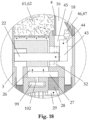
- CA 2,309,376 (Matsuyama Futoshi ) describes a vaporizer or atomizer for medical applications, consisting of ( Fig. 3 ) a vessel 1 with a liquid formulation and a rod-shaped, porous material 3, which is installed in the vessel 1.
- the rod-shaped, porous material 3 is immersed with one end in the liquid formulation, while the other end extends freely upwards outside the vessel 1.
- the vessel 1 and the rod-shaped, porous material 3 are arranged in a curved container 5.
- the curved container 5 holds the vessel 1 in position and contains an electric heating device 6, which surrounds the rod-shaped, porous material 3 in an upper end section at a distance, wherein the distance is preferably in the range 0.8-2.5 mm.
- the capillary forces in the rod-shaped, porous material 3 cause the liquid formulation to be sucked upwards, where the formulation is finally the electric heating device 6.
- the active ingredients contained in the liquid formulation are atomized and pass through the opening 9 from the curved container 5 into the room, so that they can be inhaled by the user.
- the liquid formulation consists of an aqueous solution in which an active ingredient concentrate is dissolved or dispersed.
- the aqueous solution preferably consists of water or a mixture of water and ethanol.
- the active ingredient concentrate is obtained from the leaves of Lagerstroemia Speciosa and contains up to 15% by mass of corosolic acid.
- the active ingredient concentrate is said to have a blood sugar-lowering effect.
- the proportion of the active ingredient concentrate (calculated as corosolic acid) in the aqueous solution is 0.5-3.0% by mass.
- the evaporator is designed for continuous operation.
- the electric heating device 6 is arranged at a distance from the porous material 3 and therefore does not form a bond with it.
- the gap between them represents a high thermal conduction resistance. Intermittent operation with a correspondingly high specific evaporation capacity would only be possible if the heat were transferred by thermal radiation.
- the electric heating device 6 would have to be heated rapidly to a very high temperature.
- the liquid formulation would evaporate primarily in the edge zone facing the heating device and flow through the aforementioned gap into the environment. Regardless of the practical feasibility of this concept, the vapor formed would in any case come into contact with the glowing surface of the heating device 6, causing at least partial thermal decomposition of the active ingredient concentrate.
- US 6,155,268 (Manabu Takeuchi ) describes an aroma-generating device consisting of ( Fig. 1 ) a chamber 121 with an air inlet 18 and a mouthpiece opening 22 or mouthpiece 16, whereby a gas passage channel 20 is formed, and further comprises a liquid container 32 for holding a liquid flavoring agent 34, and finally a capillary tube 36 with a first end section which is immersed in the liquid in the container 32 and a second end section which communicates with the gas passage channel 20 and further comprises a heating element 42.
- the liquid flavoring agent 34 flows through the capillary forces acting in the capillary tube 36 to the heating element 42, where it evaporates and flows as a vapor stream from the opening 36b into the gas passage channel 20
- the air flow entering the chamber 121 from the outside through the air inlet 18 is focused by the aperture 24, 24a onto the capillary opening 36b, which is intended to create favorable conditions for an intimate mixing between the vapor and the sucked-in air or for the formation of an aerosol.
- the capillary tube is filled inside with a pore structure 302, which in a variant can also protrude from the capillary tube, wherein in this latter case the heating element 425 can be arranged at the end of the protruding pore structure.
- the liquid container 32 is an integral part of the aroma-generating device.
- the liquid container can be refilled via a filling opening.
- such refilling poses risks to the environment, especially if the liquid flavoring contains pharmaceuticals or toxins such as nicotine, and the refilling is carried out by the user.
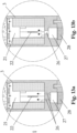
- Fig. 8 is the The liquid container is designed as a small, replaceable container. Details about the connection were not disclosed. Small, replaceable containers always pose the risk of being swallowed by small children, which can be potentially fatal, especially if the liquid flavoring contains pharmaceuticals or toxins such as nicotine.
- the arrangement according to Fig. 8 further shows a replaceable mouthpiece 161 with a hollow cylindrical extension, which lines a large part of the chamber 121 and extends almost to the mouth of the capillary 371.
- Condensate residues accumulating in the chamber 121 are deposited primarily on the inner surface of the hollow cylindrical extension and can be removed together with the mouthpiece.
- the problem is that the inner surface has only limited absorption capacity for condensate.
- the liquid flavoring contains larger proportions of low-boiling fractions with high vapor pressure - e.g. ethanol and/or water, the mouthpiece must be changed at short intervals.
- droplets form on the inner surface of the mouthpiece under the influence of surface tension, which steadily increase in volume until the adhesive forces are finally no longer sufficient to hold the droplets, and they coalesce to form larger accumulations of liquid.
- These fluid accumulations can impair the device's functionality, but can also pose a risk to the user and the environment if they contain drug residues or toxins such as nicotine. Even the possibility of having the user remove the condensate from the device themselves poses a risk to the environment.
- US$4,922,901 , US$4,947,874 and US 4,947,875 describe articles for the release or administration of drugs and/or aromas with a replaceable unit 12 containing an electrical resistance heating element 18 whose surface area is greater than at least 1m ⁇ 2/g; the electrical resistance heating element 18 carries aerosol-forming substances.
- the electrical resistance heating element 18 consists of a porous or fibrous material - e.g., carbon fibers, which material is impregnated with a liquid aerosol-forming agent.
- the articles further include a puff-activated electronic control unit 14 for controlling the current through the electrical resistance heating element 18 and are capable of administering at least 0.8 mg of aerosol or drug per puff, wherein A total of at least 10 puffs must be made before the replaceable unit 12 including the resistance heating element 18 must be replaced by a new one.
- a puff-activated electronic control unit 14 for controlling the current through the electrical resistance heating element 18 and are capable of administering at least 0.8 mg of aerosol or drug per puff, wherein A total of at least 10 puffs must be made before the replaceable unit 12 including the resistance heating element 18 must be replaced by a new one.
- the entire liquid material to be vaporized is already pre-stored in the resistance heating element 18. Liquid supply via a wick is not provided.
- the aerosol-forming substances i.e., the medication and/or any added flavorings, which are released, for example, during the last puff, have already been heated several times beforehand, which promotes thermal decomposition of the aerosol-forming substances.
- This prior heating is also disadvantageous in that it requires additional electrical energy, which does not contribute to the actual vaporization or aerosol formation. This results in a very low vaporizer efficiency.
- a further disadvantage is that, in the case of mixtures of various aerosol-forming substances, pharmaceuticals, and flavorings with different boiling points of the individual substances, the chemical composition of the resulting aerosol and its organoleptic and pharmacological effect vary from one inhalation to the next, with lower-boiling fractions increasingly evaporating during the first few puffs and higher-boiling substances increasingly being released during the final puffs.
- the replaceable unit 12 which is relatively complex to manufacture, and thus also the heating element 18, must be replaced after only about 10 puffs, making the use of these products expensive.
- US 5,060,671 and US 5,095,921 describe an article 30 ( Fig. 4 ), in which a flavor-releasing medium 111 is heated by electrical heating elements 110 to deliver inhalable flavors in vapor or aerosol form.
- the article includes multiple charges of the flavor-releasing medium 111, which are heated sequentially and thus deliver individual puffs.
- the multiple charges of the flavor-releasing medium 111 are applied to the heating elements 110, preferably as a coating, coating, or thin film, and may also include aerosol-forming substances.
- the adhesion of the flavor-releasing medium 111 to the heating elements 110 may be improved by an adhesion-promoting agent such as pectin.
- the electrical heating elements 110 and the charges of the Aroma-releasing medium 111 is preferably arranged in a replaceable unit 11, which is connected to a reusable unit 31 via electrical contact pins.
- the reusable unit 31 includes an electrical energy source 121 and an electronic control circuit 32.
- US 5,322,075 Seetharama C. Deevi et al. ) describes a similar article.
- FIG. 1A it consists of an air duct 10 with an inlet and an outlet, a plurality of carriers 28 arranged in the air duct, each carrying a specific dose of a substance/medicine, and a device for vaporizing these discrete doses.
- the air stream flowing through the inlet is directed to the carriers 28, where the condensation aerosol is ultimately formed.
- the carriers 28 each contain an electrical resistance heating element—preferably consisting of a metal foil 78 made of stainless steel.
- the metal foil heating elements 78 are preferably mounted on a circuit board ( Fig. 4 ).
- the disadvantages of the article according to US 5,060,671 and US 5,095,921 apply equally to the device according to US 2005/0268911 .
- US$5,505,214 and US 5,865,185 describe electrical smoking articles consisting of ( Fig. 4 ; US$5,505,214 ) a replaceable unit 21 and a reusable part 20.
- the replaceable unit 21 contains tobacco flavors 27 located on a carrier 36.
- the reusable part 20 contains several heating elements 23, which are supplied with current or energy from an electrical energy source - for example, a rechargeable battery - via an electrical control circuit. After inserting the replaceable unit 21 into the reusable part 20, the carrier 36 comes to rest on the heating elements 23.
- an individual heating element is activated by the control circuit, whereby the carrier 36 is heated in sections and the tobacco flavors 27 are vaporized and possibly released as an aerosol.
- the reusable part 20 contains eight heating elements 23, which allow eight inhalations or puffs, similar to a cigarette. After that, the replaceable unit 21 must be replaced with a new unit.
- US 4,735,217 (Donald L. Gerth et al. ) describes a dosing unit for administering vaporized medication in the form of fine aerosol particles, which reach the lungs through inhalation.
- the dosing unit consists in an exemplary embodiment ( Fig. 4 and 5 ) from a foil-like Nichrome ® heating element segment 72 (length ⁇ width x thickness: 1 x 1/8 x 0.001 inch), which is connected in series with a battery 65 and an airflow or draft-activated switch (60, 69).
- the drug to be vaporized - for example, nicotine - is in the form of a solid pellet 40, which the Heating element 72 is contacted.
- the drug to be vaporized can be applied directly to the heating element surface in the form of a coating or film.
- EP 1,736,065 (Hon Lik ) describes an "electronic cigarette" for atomizing a nicotine solution and essentially consists of a container 11 for holding the liquid to be atomized and an atomizer 9. Inside the atomizer 9 is an atomizer chamber 10, which is formed by the atomizer chamber wall 25. An electrical heating element 26, for example in the form of a resistance heating wire or a PTC ceramic, is arranged within the atomizer chamber 10. Ejection holes 24, 30 are also provided in the atomizer or in the atomizer wall 25, which point in the direction of the heating element 26.
- the container 11 contains a porous body 28—for example, consisting of plastic fibers or foam—which is impregnated with the liquid to be atomized.
- the atomizer chamber wall 25 is also surrounded by a porous body 27—for example, consisting of nickel foam or a metal felt.
- the porous body 27 is in contact with the porous body 28 via a bulge 36. Capillary forces cause the porous body 27, which simultaneously forms the outer shell of the atomizer 9, to be infiltrated with the liquid to be atomized.
- the atomizer further comprises a piezoelectric element 23.
- the "electronic cigarette” is operated by puff activation. During a puff, a negative pressure is created in the atomizer chamber 10, as it is connected to the mouthpiece 15. This causes air from the environment to flow into the atomizer chamber via the ejection holes 24, 30. The high flow velocity in the ejection holes 24, 30 causes liquid to be sucked out of the porous body 27 and ejected by the air stream in the form of droplets. is entrained (Venturi effect). The nicotine-containing liquid enters the atomization chamber 10, where it is atomized by ultrasound using the piezoelectric element 23.
- the heating element 26 is intended to provide additional atomization or vaporization of the nicotine solution. In an alternative embodiment, the atomization is carried out exclusively by the heating element 26.
- the invention is based on the object of overcoming the previously identified disadvantages of the arrangements known from the prior art.
- the invention is based on the object of designing an inhaler component of the type described above in such a way that the high specific vaporization power required for intermittent, inhalation-synchronized, or puff-synchronized operation can be achieved while simultaneously achieving high vaporization efficiency.
- the necessary power and energy requirements should be met by an energy storage device approximately the size of an average mobile phone battery.
- the occurrence of a boiling crisis in the wick should be avoided, and the liquid material should be able to be vaporized as gently as possible, i.e., without significant thermal decomposition.
- the inhaler component should allow for user-friendly and safe operation, while being able to be manufactured as cost-effectively as possible. Specifically, this means: The assembly should be infiltrated by the liquid material as quickly as possible, so that no significant waiting times are required between two inhalations or puffs. The inhaler component should be able to be operated in any position. The risk of liquid material—including liquid condensate residues—leaving the environment or impairing the function of the inhaler component should be minimized. The assembly should be able to be manufactured as cost-effectively as possible. The inhaler component should be handy and ergonomically designed and easy to use.
- the properties of the vapor-air mixture and/or condensation aerosol formed should be influenceable, at least within certain limits - especially the particle size distribution of the condensation aerosol formed and its organoleptic effects.
- the inhaler component is to be designed in two fundamentally different variants so that it can be used in both classic inhalers and pull-type inhalers.
- the composite is flat, and at least one heated section of the composite is arranged in the chamber without contact, and the capillary structure of the wick in said section is largely exposed on at least one side of the flat composite.
- the capillary structure of the wick in said section is largely exposed on both sides of the flat composite. Because the capillary structure of the wick in said section is largely exposed, the vapor formed can flow out of the wick unhindered, thereby increasing the evaporation performance and preventing a boiling crisis in the wick.
- Layer-to-layer bonding means that the heating element and the wick are arranged and connected in the same area or/and in parallel surfaces.
- the capillary transport of the liquid material in the layer-to-layer bonding occurs primarily in the direction of the surface.
- Non-contact means that neither the chamber wall nor other structural elements of the inhaler component are touched; the non-contact arrangement in the chamber ensures that the thermal conduction losses of the composite in this section are significantly reduced and the composite is heated to such an extent that the liquid material stored in the wick can evaporate.
- ducts are also intended to include ducts; thus, a tubular duct also falls under the term “chamber”; in this case, an open pipe end could, for example, form the air inlet opening.
- the planar composite has a thickness of less than 0.6 mm, and in a particularly preferred embodiment, a thickness of less than 0.3 mm.
- This dimensioning results in the heat introduced across the surface being able to flow efficiently through thermal conduction—that is, at a small temperature gradient—to the exposed wick surface or capillary structure, where it causes the evaporation of the liquid material.
- the vapor formed can also more easily reach the exposed wick surface.
- These conditions enable a further increase in evaporation performance and contribute to the particularly gentle evaporation of the liquid material. It should be noted that this is not simply a matter of dimensioning, but rather an essential feature of the invention. Even the inventor was surprised when he discovered in experiments that flat wicks with an exposed wick surface and a thickness of ⁇ 300 ⁇ m still exhibit a wicking effect in the surface direction.
- the composite is formed in plate, film, strip, or band form.
- the planar composite contains one of the following structures: woven fabric, open-pore fiber structure, open-pore sintered structure, open-pore foam, or open-pore deposition structure.
- These structures are particularly suitable for creating a wick body with high porosity. High porosity ensures that the heat generated by the heating element is largely used to evaporate the liquid material contained in the pores, and a high evaporator efficiency can be achieved. Specifically, these structures can achieve a porosity greater than 50%.
- the open-pore fiber structure can, for example, consist of a nonwoven fabric that can be densified as desired and additionally sintered to improve cohesion.
- the open-pore sintered structure can, for example, consist of a granular, fibrous, or flaky sintered composite produced by a film casting process.
- the open-pore deposition structure can, for example, be produced using a CVD process, PVD process, or flame spraying.
- Open-pore foams are generally commercially available and are also available in thin, fine-pored versions.
- the planar composite comprises at least two layers, wherein the layers contain at least one of the following structures: plate, film, paper, fabric, open-pore fiber structure, open-pore sintered structure, open-pore foam, open-pore deposition structure.
- Certain layers can be assigned to the heating element, and other layers to the wick.
- the heating element can by an electrical heating resistor consisting of a metal foil.
- the individual layers are advantageously, but not necessarily, bonded together by heat treatment such as sintering or welding.
- the composite can be formed as a sintered composite consisting of a stainless steel foil and one or more layers of a stainless steel wire mesh (material, e.g., AISI 304 or AISI 316).
- a stainless steel wire mesh material, e.g., AISI 304 or AISI 316.
- heating conductor alloys in particular, NiCr alloys and CrFeAl alloys (“Kanthal”)—can also be used, which have an even higher specific electrical resistance than stainless steel.
- the heat treatment creates a material bond between the layers, whereby the layers maintain contact with each other—even under adverse conditions, for example, during heating by the heating element and the resulting thermal expansion. If the contact between the layers were lost, a gap could form, which could disrupt the capillary coupling on the one hand and the heat transfer from the heating element to the liquid material on the other.
- the composite is linear, and at least one heated section of the composite is arranged in a contact-free manner in the chamber, with the capillary structure of the wick being largely exposed in said section. Because the capillary structure of the wick is exposed in said section, the vapor formed can flow unhindered from the wick, thereby increasing the evaporation performance and preventing a boiling crisis in the wick.
- the capillary transport of the liquid material in the linear composite occurs primarily in the longitudinal direction of the linear composite.
- the linear composite preferably has a thickness of less than 1.0 mm, the thickness being defined by: 4 * A / ⁇ (A denotes the cross-sectional area of the composite).
- the linear composite contains at least one of the following structures: wire, yarn, open-pore sintered structure, open-pore foam, or open-pore deposited structure. These structures are particularly suitable for producing a linear composite with sufficient mechanical stability and high porosity.
- the heating element is at least partially integrated into the wick.
- This arrangement has the advantageous effect that the heat is generated and released directly in the wick body, where it is transferred directly to the liquid material to be evaporated.
- the heating element can consist of an electrically conductive thin film of platinum, nickel, molybdenum, tungsten, or tantalum, which is applied to the wick surface using a PVD or CVD process.
- the wick consists of an electrically non-conductive material—e.g., quartz glass.
- the wick itself consists at least partially of an electrical resistance material, for example, carbon, an electrically conductive or semiconductive ceramic, or a PTC material.
- the electrical resistance material is metallic.
- Metals exhibit greater ductility than the aforementioned materials. This property proves advantageous in that the composite is subjected to alternating thermal stress during operation, which induces thermal expansion. Metals can better compensate for such thermal expansion. Furthermore, metals exhibit comparatively higher impact strength. This property proves advantageous when the inhaler component is exposed to impacts.
- Suitable metallic resistance materials include, for example, stainless steels such as AISI 304 or AISI 316, as well as heat conductor alloys—particularly NiCr alloys and CrFeAl alloys (“Kanthal”) such as DIN material numbers 2.4658, 2.4867, 2.4869, 2.4872, 1.4843, 1.4860, 1.4725, 1.4765, and 1.4767.
- the connection between the heating element and the wick extends over the entire length of the wick. It is irrelevant whether the heating element is used as such—i.e., heated—over its entire length or only in sections. This depends on the respective position of the electrical contact of the heating element. Even if this contact is made at the outer ends of the heating element, the heating element does not necessarily have to contribute to the evaporation of the liquid material over its entire length. Thus, the heating element can partially contact structural components that largely dissipate the heat generated in the heating element, so that the liquid material in the wick is practically not heated, at least in this section. However, this dissipated heat would be considered a loss in the energy balance.
- the flat composite can be produced in large quantities from a flat, multiple-panel assembly by separating the composite from the multiple-panel assembly using suitable separation processes such as punching or laser cutting.
- the linear composite can advantageously be produced from a continuous material.
- continuous material also includes a material with a finite length, provided this length is several times greater than the length of the linear composite.
- a high porosity of the wick or composite is desirable for effective utilization of the thermal energy introduced by the heating element.
- Porosity can be further increased by etching the composite or its production precursor—e.g., the multiple panel.
- a sintered composite consisting of a stainless steel foil and one or more layers of a stainless steel mesh (e.g., AISI 304, AISI 316) can be treated accordingly in an aqueous pickling bath consisting of 50% nitric acid and 13% hydrofluoric acid.
- the electrical resistance of the heating element or composite can also be influenced, namely increased.
- the surface of the composite or its production precursor can also be activated.
- This measure also includes This facilitates cleaning of the surface and results in better wetting of the composite material by the liquid material, thus facilitating faster infiltration of the wick.
- a treatment with 20% phosphoric acid is ideal for achieving the aforementioned effects.
- the wick is designed as an arterial wick.
- This type of wick is primarily used in heat pipes and is described in more detail in the relevant literature – see, for example, ISBN 0080419038.
- Such a wick can, for example, consist of a bundle of channels or capillaries – so-called "arteries" – which are surrounded by or formed by a finer pore structure.
- the bundle of channels or capillaries offers less flow resistance to the liquid material, which can significantly accelerate the infiltration of the wick with the liquid material.
- the wick is perforated across its thickness.
- the perforation can be achieved, for example, using a laser and has the following effects: firstly, the porosity is further increased; secondly, the flow resistance along the thickness is reduced.
- the latter effect is particularly evident when using an arterial wick, as the liquid material in the wick experiences an increase in pressure during evaporation, and the perforation acts as a pressure relief. This prevents the vapor formed in the wick from forcing the liquid material back through the arteries to the source of the liquid material, which can severely disrupt the supply of liquid material.
- planar composite is essentially flat, and the air inlet opening is designed as a slot-shaped channel, and the slot-shaped channel is aligned parallel to the planar composite surface.
- linear composite is essentially straight, and the air inlet opening is designed as a slot-shaped channel, and the slot-shaped channel is aligned parallel to the straight composite.
- the composite extends through the chamber in a bridge-like manner and rests with two end sections on two electrically conductive, plate-shaped contacts, and the heating element is electrically contacted with the contacts.
- the electrical contacting of the heating element consists of a welded or sintered connection.
- the welded connection can be produced by spot welding, resistance welding, ultrasonic welding, laser welding, bonding, or other suitable welding methods.
- the electrical contact of the heating element consists of an adhesive connection using an electrically conductive adhesive, for example, a silver-containing epoxy-based adhesive.
- the plate-shaped contacts can, in principle, be made of any electrical contact material, as long as the material is compatible with the adhesive used; alternatively, the plate-shaped contacts can also be formed by printed circuit boards or a common printed circuit board. Thick copper circuit boards with copper layer thicknesses in the range of 100-500 ⁇ m are preferred due to better heat dissipation.
- the invention is not limited to the contacting methods mentioned above.
- the electrical contact could alternatively be made by mechanical clamping.
- the plate-shaped contacts protrude from the outer surface of the housing in the form of two plug contacts. The two plug contacts are intended to supply the required electrical energy to the heating element.
- one end of the composite extends into a capillary gap whose flow resistance is lower than the flow resistance of the wick.
- the capillary gap feeds the wick with liquid material; the reduced flow resistance compared to the wick causes the liquid material to reach the vaporization zone in the composite more quickly. This also shortens the time required to completely reinfiltrate the wick with liquid material after vaporization. This time corresponds to a waiting period that must be observed at least between two puffs or inhalations. Failure to observe this waiting period can lead to a reduction in the emitted vapor quantity or drug dose. Furthermore, heating the composite in sections without liquid material can lead to local overheating, which can damage the composite or shorten its service life.
- the cross-section of the capillary gap is larger than the cross-section of the composite. This has the effect that the liquid material partially bypasses the wick, thus reaching the evaporation zone in the composite even faster.
- the heating element of the composite is electrically contacted in the capillary gap. This results in a very space-saving arrangement.
- a preferred embodiment of the invention relates to an inhaler component with a liquid container containing the liquid material, arranged in the housing or connected to the housing, and with an openable closure.
- the liquid container can neither be removed from the housing nor separated from the housing, and the liquid material in the liquid container can be capillary coupled to the capillary gap by manually opening the openable closure.
- the liquid container cannot therefore be removed from the inhaler component by the user, even if the liquid material has been used up, which is to be considered a safety advantage, especially if the container contains medicines and/or poisons. such as nicotine.
- the housing of the inhaler component is too large to be swallowed by small children.
- the liquid material is stored hermetically sealed in the liquid container. Access to air or UV rays is largely excluded.
- the liquid container can also contain a protective gas such as argon, nitrogen, or carbon dioxide, which additionally protects the liquid material from oxidation.
- the openable closure of the liquid container is expediently only opened shortly before the inhaler component is used, after which the liquid material flows through the capillary gap to the wick and infiltrates it. The openable closure is easily opened manually without the aid of any special tools.
- the liquid container is rigidly and permanently connected to the housing, or itself forms part of the housing.
- the liquid container can, for example, be designed as a separate part that is inseparably connected to the housing by an adhesive or welded joint.
- a reservoir communicating with the capillary gap is provided, which reservoir adjoins the liquid container and is separated from it by the openable closure. The reservoir serves to collect at least a portion of the liquid material from the liquid container when the closure is open and to ensure capillary coupling with the capillary gap.
- the openable closure is preferably opened by a pin that is axially displaceably mounted in the housing, the first end of which is directed towards the openable closure, and the second end of which protrudes from the outer surface of the housing like an extension when the closure is closed, by a compressive force being exerted on the second end of the pin.
- the pressure force is transferred from the pin to the openable closure, which ultimately tears open along a predetermined breaking point.
- the pressure force can be generated, for example, by finger pressure.
- a particularly advantageous embodiment of the invention relates to an inhaler comprising an inhaler component as just described and a reusable Inhaler part that can be coupled to the inhaler component; according to the invention, the second end of the pin is in a plunger-like operative connection with the reusable inhaler part during coupling, thereby generating the previously described pressure force.
- the coupling of the inhaler component with the reusable inhaler part and the opening of the liquid container thus occur simultaneously through a single manipulation.
- the reservoir communicates with the chamber via a vent channel, allowing air to enter the reservoir and causing pressure equalization.
- a vent channel allowing air to enter the reservoir and causing pressure equalization.
- the liquid container is arranged in the housing so that it can be manually displaced along a displacement axis between two stop positions.
- the liquid container interacts with a non-releasable blocking device and, in the second stop position, with an opening means that opens the openable closure.
- the blocking device fundamentally prevents removal of the liquid container from the housing.
- the opening means comprises a first spike formed by the capillary gap, which penetrates the openable closure in the second stop position, thereby establishing the capillary coupling with the liquid material.
- a ventilation channel is provided, the first end of which communicates with the chamber and the second end of which is designed as a second spike, which penetrates the openable closure in the second stop position.
- the first and second spikes together form the opening means.
- the effect of this arrangement is similar to that of a coupling between a fountain pen and its ink cartridge.
- the first and second mandrels can also be fused into a single common pin.
- the non-releasable blocking device can easily consist of a projection formed, for example, by the housing or the mouthpiece, against which the liquid container abuts in the first stop position.
- the second embodiment variant relates to an inhaler component comprising a mouthpiece with a mouthpiece channel through which a user receives the vapor-air mixture and/or condensation aerosol.
- the displacement axis is aligned at least approximately parallel to the central axis of the mouthpiece channel, and the liquid container protrudes from the housing with an end section laterally next to the mouthpiece, at least in the first stop position.
- the displaceable liquid container can easily be displaced into its second stop position by the user pressing on the protruding end of the liquid container.
- the mouthpiece and the liquid container protrude from the housing on the same end face of the inhaler component, which makes the inhaler component handy and its use ergonomic.
- a buffer reservoir can also be provided, which communicates with the capillary gap and itself consists of capillaries.
- the buffer reservoir has the ability to absorb liquid material from the capillary gap and, when needed, release the buffered liquid material back to the wick via the capillary gap, regardless of position. This allows the inhaler component to be operated in any position, at least as long as liquid material is available in the buffer reservoir.
- the capillaries can consist, for example, of slits, holes, or a porous material. Care must be taken to ensure that their capillarity or capillary pressure (capillary rise) is lower than the capillarity of the wick, since otherwise no capillary flow will occur.
- the inhaler component can contain a liquid reservoir made of an elastic, open-pore material and impregnated with the liquid material; according to the invention, the composite is sandwiched between one of the two plate-shaped contacts - as already described - on the one hand, and the liquid reservoir on the other hand, whereby the wick is capillary-connected to the liquid material in the liquid reservoir.
- the elastic, open-pored material can be made of fiber or foam, for example. The liquid material is automatically drawn from the fluid reservoir into the wick and infiltrates it. This requires that the capillarity or capillary pressure (capillary rise) of the wick is greater than the capillarity of the fluid reservoir.
- the sandwich-like clamping represents a structurally simple and cost-effective arrangement.
- the inhaler component includes a condensate binding device for absorbing and storing condensate residues formed during the generation of the vapor-air mixture and/or condensation aerosol.
- a condensate binding device for absorbing and storing condensate residues formed during the generation of the vapor-air mixture and/or condensation aerosol.
- condensate residues can arise, particularly when the liquid material to be vaporized contains large proportions of low-boiling fractions with high vapor pressure, e.g., ethanol and/or water.
- Such proportions of low-boiling fractions are advantageous for two main reasons and, in the case of the inhaler component according to the invention, are also necessary: firstly, such proportions reduce the viscosity of the liquid material, allowing the liquid material to infiltrate the wick more quickly.
- the low-boiling fractions ensure that pharmaceuticals and other additives contained in the liquid material evaporate more easily, less evaporation residues form, and the thermal decomposition of the liquid material is reduced.
- the mass fraction of the low-boiling fractions should be significantly above 50%. Consequently, significant amounts of condensate residues are to be expected during operation of the inhaler component according to the invention, which must be appropriately bound.
- the condensate binding device consists of an open-pored, absorbent body, which is arranged at a distance from, but in close proximity to, the capillary structure of the wick exposed in said section.
- the open-pored, absorbent body absorbs condensate deposits formed from the vapor phase in its pores and thus acts in a similar way to like a sponge. Even a larger amount of condensate can be easily absorbed.
- the open-pored, absorbent body prevents freely moving condensate accumulations from forming in the inhaler component, particularly in the chamber. These accumulations can impair the function of the inhaler component and also pose a risk to the user and the environment if these accumulations contain drug residues or toxins such as nicotine.
- the open-pored, absorbent body in the immediate vicinity of the vapor formation zone - i.e. in an area of high vapor density - ensures that the condensate residues are absorbed in very high concentrations and thus very effectively, and are not even given the opportunity to spread to peripheral areas. It is particularly advantageous if the open-pored, absorbent body directly covers the capillary structure of the wick that is exposed in this section, since the highest vapor density is to be expected in this zone.
- the open-pored, absorbent body comprises two spaced-apart parts or sections, and the composite is arranged at least partially between the two parts or sections.
- the open-pored, absorbent body is arranged in the chamber and fills the majority of the chamber. In this way, a particularly large absorption capacity for the liquid condensate residues can be achieved with a compact design. It is also advantageous if the open-pored, absorbent body is made of a dimensionally stable material that largely retains its shape even after complete infiltration with the condensate residues. To determine whether a specific material is dimensionally stable, it is sufficient to soak it in an ethanol-water solution and to check its dimension stability after a three-day residence time.
- the open-pored, absorbent body can be made of a solid foam-like material such as metal foam or ceramic foam, of a porous sintered molded body, of a porous filling or bulk material without swelling tendency, for example of a desiccant granulate bed, or of a porous fiber composite, for example formed from thermally or with It can consist of natural or synthetic fibers bonded together with the aid of a binding agent. It is also essential that the material is largely chemically inert to the condensate residues.
- the open-pored, absorbent body is largely enclosed by the housing and is inseparably connected to the housing. This is intended to ensure that the open-pored, absorbent body cannot come into direct contact with the environment, and its removal from the housing is only possible through the use of force and destruction of the inhaler component.
- This protective measure proves particularly advantageous when the condensate contains drug residues and/or toxins such as nicotine.
- the inhaler component, together with the open-pored, absorbent body, forms a disposable article that must be properly disposed of after its intended service life has been reached.
- a two-stage condensate separation device consisting firstly of the open-pored, absorbent body and secondly of a cooler through which the vapor-air mixture and/or condensation aerosol formed can flow.
- This development of the invention is particularly suitable for use in puff inhalers.
- the cooler cools the vapor-air mixture and/or condensation aerosol flowing through it and, in the process, removes further condensate.
- the cooler can, for example, be formed by a porous body that is permeable to flow and largely permeable to the particles of the formed condensation aerosol.
- the porous body In addition to cooling, the porous body also ensures intimate mixing of the vapor-air mixture or condensation aerosol flowing through it, thereby homogenizing its properties, for example, reducing concentration peaks.
- the porous body is typically made of a wide-pore material, for example, an open-cell foam material, a coarse-pored, porous filling material, or a nonwoven fiber material. Examples of nonwoven fiber materials include synthetic fiber nonwovens made of polyolefin fibers (PE, PP) or polyester fibers.
- the porous body can also consist of a regenerator material. The regenerator material is capable of absorbing large amounts of heat quickly and without significant flow losses, given a large surface area or heat exchange area.
- Typical Regenerator materials include: metal wool, metal shavings, metal mesh, wire mesh, metal fiber fleece, open-cell metal foams, and bulk materials made of metallic or ceramic granules.
- the cooler can also be constructed in multiple stages by combining various porous materials. Of course, the invention is not limited to the cooler materials listed above. Cooling and homogenization can significantly improve the organoleptic properties of the vapor-air mixture and/or condensation aerosol absorbed by the user.
- the cooler is formed by a tobacco filling.
- the tobacco filling also flavors the vapor-air mixture or condensation aerosol flowing through it and is particularly suitable when the liquid material contains nicotine as a pharmaceutical.
- Laboratory tests with prototypes operating according to the puff-inhaler principle and with nicotine-containing pharmaceutical preparations as the liquid material have also revealed further beneficial effects: for example, the inhalability of the nicotine-containing vapor-air mixture and condensation aerosol could be improved, which is certainly partly attributable to the effects described above.
- additional mechanisms of action are involved—particularly diffusion and adsorption processes concerning the free, unprotonated nicotine—which still require detailed research.
- the filling density of the tobacco filling is limited by the fact that, on the one hand, the filling must be as permeable as possible to the aerosol particles flowing through it, and, on the other hand, the induced flow resistance should not be greater than that of cigarettes.
- the tobacco filling can be made from cut tobacco, fine-cut tobacco, pipe tobacco, a cigar-like tobacco wrap, or from comparable or similar tobacco forms. Suitable tobacco products include, in particular, dried, fermented tobacco, reconstituted tobacco, expanded tobacco, or mixtures thereof. The tobacco can additionally be flavored, spiced, aromatized, and/or perfumed.
- the use of a tobacco filling as a cooler can also make the switch from tobacco products to the inhaler component according to the invention more attractive and/or easier.
- a preferred embodiment of the invention provides that the volume of the tobacco filling is greater than 3 cm3. Our own laboratory tests have shown that the above-mentioned effects of the tobacco filling only become apparent to a degree satisfactory to the user above the previously specified minimum volume.
- the inhaler component comprises a mouthpiece opening formed by a mouthpiece, which communicates with the chamber and through which a user receives the vapor-air mixture and/or condensation aerosol.
- a flow develops between the air inlet opening and the mouthpiece opening in the direction of the mouthpiece opening, which flow passes through the composite at least in sections.
- at least one air bypass opening is arranged downstream of the composite, through which additional air from the environment is fed into the flow, and the effective flow cross-section of the air bypass opening is at least 0.5 cm2. This arrangement also makes the inhaler component usable for conventional inhalers, which generally require the lowest possible flow resistance.
- bypass air The additional air flowing in through the air bypass opening
- bypass air reduces the amount of air flowing in through the air inlet opening ("primary air”), assuming a constant inhalation air volume.
- primary air the amount of air flowing in through the air inlet opening
- a reduction in the primary air volume leads, among other things, to an increase in the number of aerosol particles formed; at the same time, however, the amount of condensate residue formed also increases, a circumstance that can be counteracted by the provision of a condensate binding device - as described above.
- a further reduction in flow resistance and a further reduction in the primary air volume are achieved according to the invention in that the air bypass opening consists of two bypass openings arranged in opposite housing sections.
- two guide vanes are connected to the two bypass openings, which point towards the mouthpiece opening and converge, and whose free ends form a nozzle-shaped opening through which the vapor-air mixture and/or condensation aerosol formed flows out of the chamber and subsequently mixes with the air flowing in from the bypass openings.
- the two guide vanes have the effect of largely covering the chamber from the outside, thereby significantly reducing the risk of rainwater or saliva, for example, entering the chamber.
- the air exchange between the chamber and the environment is also restricted, thereby reducing the natural evaporation of portions of the liquid material in the wick.
- Such evaporation can prove disadvantageous, particularly during extended periods of non-use of the inhaler component, as the composition of the liquid material can change and, in the case of pharmaceuticals, the dosage can deviate from the target value.
- a flow homogenizer is arranged downstream of the air bypass opening, the flow resistance of which is less than 1 mbar at an air throughput of 250 mL/sec.
- the flow homogenizer is flowed through by both the vapor-air mixture formed and/or condensation aerosol as well as the bypass air flowing in through the air bypass opening, and this causes mixing and homogenization of these two flow components. Concentration peaks are reduced, and the homogenized mixture emerging from the mouthpiece opening is more pleasant for the user to inhale.
- the flow homogenizer can, for example, consist of a fleece-like or foam-like material; such a material is suitable for generating sufficient flow turbulence and vortex without exceeding the stated limit for flow resistance. Only in this way can the inventive design just described be used for a conventional inhaler.
- This special embodiment proves to be particularly advantageous when the heating resistors are made of a metallic resistance material such as stainless steel or heat conductor alloys, since the series connection and the resulting increase in resistance allows the heating current to be limited to a level that is still easily manageable by the electronic control system and the energy storage device. Furthermore, the increase in resistance allows the power density in the assembly to be throttled as needed, thus ensuring stable evaporation in all cases.
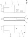
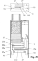
- Fig. 1 shows a first embodiment of an inhaler according to the invention, which in the specific example is designed as a puff inhaler, and whose shape and size are designed such that the inhaler can be handled easily and comfortably by users.
- the inhaler is only about half the size of a cigarette pack.
- the inhaler shown as an example basically consists of two parts, namely an inhaler part 1 and an inhaler component 2.
- the inhaler component 2 consists of a housing 3 and includes, among other things, a liquid container 4 and a tobacco pipe-like mouthpiece 5.
- the liquid container 4 contains a liquid material, which evaporates in the inhaler component 2 and is converted into an inhalable vapor-air mixture and/or condensation aerosol.
- the resulting vapor-air mixture and/or condensation aerosol is presented to the user via mouthpiece 5.
- all substances and preparations that can be vaporized largely without residue under atmospheric conditions can be considered as liquid material. This condition is already met if the respective substance or preparation is diluted, for example dissolved in water and/or ethanol, and the solution evaporates largely without residue.
- a highly volatile solvent such as ethanol and/or water, even substances that are otherwise difficult to vaporize can fulfill the aforementioned condition, and thermal decomposition of the liquid material can be avoided or significantly reduced.
- the liquid material preferably contains a drug.
- the aerosol particles generated by condensation generally have a mass median aerodynamic diameter (MMAD) of less than 2 ⁇ m and thus also reach the alveoli.
- MMAD mass median aerodynamic diameter
- the inhaler according to the invention is particularly suitable for the administration of systemically acting drugs, such as those that exert their primary effect in the central nervous system.
- One example is nicotine, whose boiling point is 246°C.
- the aerosol particles containing the drug are predominantly deposited in the alveoli, where the drug rapidly enters the bloodstream.
- nicotine it should be noted that it reaches its target organ—namely, the central nervous system—in concentrated concentrations just 7-10 seconds after inhalation.
- the inhaler in question could also be operated without a drug, for example, with only flavorings—even in non-medical applications.
- the inhaler part 1 contains, as will be explained in more detail below, at least one energy storage device and an electrical circuit, wherein the energy storage device is protected by a battery cover 6 and the circuit is protected by a circuit cover 7.
- the inhaler part 1 and the inhaler component 2 are designed to be detachable from one another in the specific embodiment.
- the detachable coupling consists of a snap connection formed by two snap hooks 8 and two locking lugs 9 interacting with them.
- This arrangement makes the inhaler part 1 reusable, which is generally useful if It takes into account that, firstly, the inhaler part 1 does not come into contact with the liquid material, i.e., is not contaminated by the liquid material, and secondly, it contains components that are more durable than the components of the inhaler component 2. After the liquid material in the liquid container 4 has been used up, the inhaler component 2 is properly disposed of as a whole by the user and replaced with a new inhaler component 2.
- the inhaler component 2 is therefore a replaceable, disposable article. Proper disposal is particularly advisable when the liquid material contains medication, because condensate residues always form and settle inside the housing 3 of the inhaler component 2 during the formation of the vapor-air mixture and/or condensation aerosol. Residues of the liquid material also always remain in the liquid container 4.
- the inhaler part 1 and the inhaler component 2 are designed as a single piece, i.e., inseparable from one another.
- this embodiment is likely to be less economical because in this case, all parts and components of the inhaler, i.e., the inhaler as a whole, constitute a disposable item for single use.
- the present invention also encompasses this embodiment, although in this case, the entire inhaler is considered the inhaler component.
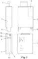
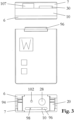
- the Fig. 3 to 5 show various views of the reusable inhaler part 1 with and without a lid.
- the reusable inhaler part 1 is essentially composed of the following three housing parts: the battery cover 6, the circuit cover 7, and a carrier housing 10 arranged between them.
- the three housing parts are preferably made of plastic.
- the carrier housing 10 accommodates the electrical circuit 11 and the energy storage device 12 and comprises a partition 13 that separates the circuit 11 and the energy storage device 12 from each other.
- the electrical circuit 11 is designed as a single-sided printed circuit board, which is attached to the partition 13, for example, by an adhesive connection.
- the energy storage device 12 preferably consists of a rechargeable battery, for example a lithium-ion battery or a lithium-polymer battery, preferably in a flat design.
- a rechargeable battery for example a lithium-ion battery or a lithium-polymer battery, preferably in a flat design.
- These battery types currently provide the highest energy densities and currents and have been used in a variety of ways for a long time, whereby First and foremost, the widespread use in mobile phones is worth mentioning.
- the power supply from the battery 12 to the circuit board 11 is via two flat contacts 14, which are soldered onto the back of the circuit board 11 - see also Fig. 10
- the flat contacts 14 protrude through two slightly larger windows 15 in the partition 13.
- the battery 12 comprises two corresponding contacts (not shown), which are pressed against the flat contacts 14, thereby establishing a releasable electrical contact.
- the compressive force required for this purpose is preferably generated by a leaf spring (not shown) arranged between the battery 12 and the battery cover 6.
- the battery cover 6 is releasably connected to the carrier housing 10 - in the exemplary embodiment by means of a screw connection (see Fig. 1 ).
- the battery cover 6 could alternatively be designed as a latchable sliding cover.
- the circuit cover 7 is preferably inseparably connected to the carrier housing 10, for example by means of an adhesive or welded connection. This is intended to prevent unauthorized manipulation of the circuit 11. In the normally rare event of a circuit defect, the entire inhaler part 1, with the exception of the battery 12, must be replaced. Further components and properties of the reusable inhaler part 1 will be described in more detail later.
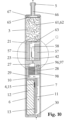
- the replaceable inhaler component 2 is essentially formed by the housing 3 and includes, among other things, the liquid container 4 and the tobacco pipe-like mouthpiece 5.
- the liquid container 4 and the mouthpiece 5 are inseparably connected to the housing 3. From a manufacturing point of view, it is advantageous to manufacture the liquid container 4 and the mouthpiece 5 as separate parts and to connect them to the housing 3 in a subsequent step, for example by means of an adhesive or welded joint - see Fig. 7 . In principle, it is of course also conceivable to form the liquid container 4 and/or the mouthpiece 5 as a single piece with the housing 3.
- the housing 3, the liquid container 4 and the mouthpiece 5 are preferably made of plastic for weight reasons, whereby the properties of the liquid material 16 must be taken into account when selecting the material for the liquid container 4. If the liquid material 16 contains for example, nicotine, plastics can be US 5,167,242 (James E. Turner et al. ) and US 6,790,496 (Gustaf Levander et al. ) are used.
- the liquid container 4 is filled with the liquid material 16 via a filling hole 17, preferably under a protective gas atmosphere such as argon or nitrogen.
- a flap-like, openable closure 18 On one end of the liquid container 4 is a flap-like, openable closure 18, which is opened by the user before use of the inhaler component 2.
- the openable closure 18 will be described in more detail later.
- the liquid container 4 is never completely filled with the liquid material 16. Due to the incompressibility of the liquid material 16, complete filling would result in the flap-like, openable closure 18, which always has a certain elasticity, no longer being able to be pressed in and opened.
- the filling hole 17 is hermetically sealed with a closure cap 19.
- the closure cap 19 can, for example, be glued or welded on, whereby any heat exposure to the liquid material 16 should be avoided as far as possible.
- the filling hole 17 can be designed as a capillary bore, and filling with the liquid material 16 can be performed via an injection needle.
- the closure cap 19 could be omitted, and the capillary bore itself could be sealed. Further components and properties of the replaceable inhaler component 2 will be described in detail later.
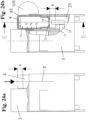
- Fig. 8 shows the inhaler Fig. 1 with the circuit cover removed 7.
- the snap connection consisting of the two snap hooks 8 and the corresponding locking lugs 9, in the coupled, engaged state.
- the snap hooks 8 are designed as extensions of the housing 3, while the locking lugs 9 are formed by contact elements 20.
- the contact elements 20 are attached to the carrier housing 10 of the reusable inhaler part 1 by an adhesive connection and fulfill additional functions, which will be described in detail later.
- Contact is preferably made either by a flat adhesive connection using a conductive adhesive - e.g. adhesives from Epoxy Technology, www.epotek.com - or by a welded connection.
- a conductive adhesive e.g. adhesives from Epoxy Technology, www.epotek.com - or by a welded connection.
- a welded connection care must be taken to ensure that the wick or its capillary structure is not impaired by the weld, if possible. If necessary, the weld should only be carried out at specific points.
- the choice of material for the plate-shaped contacts 23 information has already been given earlier.
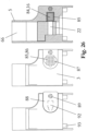
- the area between the two plate-shaped contacts 23 defines the heated section of the planar composite 22, which is arranged in a contact-free manner in the chamber 21.
- the contact-free arrangement results in the thermal conduction losses in the thickness direction of the planar composite 22 being zero.
- this section can heat up to such an extent that the liquid material 16 stored in the wick reaches boiling temperature and evaporates.
- the capillary structure of the wick is largely exposed in said section, at least on one side of the planar composite. This side, as will be explained later in the course of the description of exemplary embodiments of the composite, is preferably the side 24 of the planar composite 22 facing away from the plate-shaped contacts 23.
- the vapor formed during the evaporation of the liquid material can therefore flow out of the exposed capillary structure of the wick over a wide area and without significant obstruction.
- the capillary structure of the wick in the said section is also largely exposed on the side 25 of the planar composite 22 opposite side 24, so that the evaporation surface and Consequently, the maximum achievable evaporation performance is doubled compared to the first case.
- the maximum achievable evaporation performance is defined by the first occurrence of a boiling crisis in the wick.
- the housing 3 further forms an air inlet opening 26 for the supply of air from the environment into the chamber 21.
- the supplied air mixes in the chamber 21 with the vapor flowing out of the exposed capillary structure of the wick, during which the vapor-air mixture and/or condensation aerosol is formed.
- the air inlet opening 26 is designed as a slit-shaped channel.
- the slit-shaped channel is aligned parallel to the planar composite 22.
- the slit-shaped channel is arranged slightly laterally offset from the planar composite 22, namely on that side of the planar composite on which the capillary structure of the wick is largely exposed.
- This arrangement ensures that the air flowing into the chamber 21 through the slit-shaped channel 26 completely flows over the exposed capillary structure of the wick, and homogeneous mixing conditions can be established.
- the flow velocity of the incoming air can be changed, and in this way the dynamics of aerosol formation and, in connection with this, the properties of the aerosol produced can be influenced to a certain extent.
- a reduction in the flow velocity causes the aerosol particles to increase in average size.
- the geometric position of the slit-shaped channel 26 in relation to the planar composite 22 also influences aerosol formation.
- the Fig. 13a and 13b show alternative arrangements of the air inlet opening 26; accordingly, the air inlet opening 26 in the example according to Fig. 13a formed by two slot-shaped channels 26, which are arranged on opposite sides of the planar composite 22.
- the planar composite 22 is thus surrounded on both sides by the air flowing into the chamber 21.
- the slot-shaped channel 26 is arranged centrally to the planar composite; in this case, the planar composite 22 lies in the plane of the slot-shaped channel and is directly exposed to the incoming air, whereby the air flow is split into two parts by the planar composite, and the composite consequently flows around on both sides as in the previous example
- 13a and 13b are particularly suitable for the design variant of the planar composite 22, in which the capillary structure of the wick is exposed on both sides, since in this case, vapor flows from both sides 24 and 25 of the planar composite 22.
- they are also suitable for the design variant of the planar composite 22 with the capillary structure exposed on only one side, insofar as the second air flow component, which flows quasi-passively around the composite, weakens the first air flow component that causes the aerosol formation, which in turn can influence the properties of the aerosol formed.
- a flow restrictor 28 Upstream of the plenum chamber 27 is a flow restrictor 28.
- the purpose of the flow restrictor 28 is to create a flow resistance similar to that of a cigarette, so that the user feels a similar resistance during a puff to that experienced when taking a puff on a cigarette.
- the flow resistance should be in the range of 12-16 mbar at a flow rate of 1.05 L/min and have a characteristic that is as linear as possible.
- the flow restrictor 28 can, for example, be formed from an open-pore sintered body made of metal or plastic, whose pores are penetrated by air. Porous plastic molded bodies from Porex, www.porex.com, have proven successful in prototypes.
- the plenum chamber 27 is part of the replaceable inhaler component 2 and the flow restrictor 28 is part of the reusable inhaler part 1.
- the Fig. 10 shows the further course of the air flow upstream of the flow restrictor 28.
- the flow is indicated by arrows.
- the flow restrictor 28 draws the air from a transverse channel 29, which in turn opens into the space between the circuit board 11 and the circuit cover 7.
- the actual supply of air from the environment takes place via a feed opening 30 formed by the circuit cover 7.
- the feed opening 30 is on the Located on the front side of the inhaler opposite the mouthpiece 5. This position provides the best protection against the ingress of rainwater.
- the Fig. 14a, 14b and 15a, 15b, 15c show exemplary forms of the planar composite 22 using cross-sectional representations, whereby "cross-section” is understood to mean a section normal to the longitudinal direction of the composite (cf. Fig. 9 ).
- the Fig. 14a and 14b Embodiments with only one-sided exposed capillary structure
- the Fig. 15a to 15c Embodiments show in which the capillary structure of the wick is exposed on both sides of the planar composite.
- the flat composite 22 consists of four layers: namely, a metal foil 31 and three metal wire meshes 32 sintered onto it.
- the metal consists of stainless steel (e.g., AISI 304 or AISI 316) or a heat-conducting alloy—particularly from the group of NiCr alloys or CrFeAl alloys ("Kanthal").
- AISI 304L or AISI 316L preference is given to low-carbon alloys (e.g., AISI 304L or AISI 316L) because they are less susceptible to intergranular corrosion.
- the metal foil 31 can be obtained in stainless steel, for example, from Record Metall-Folien GmbH, www.recordmetall.de.
- the wire meshes can be obtained, for example, from Haver & Boecker, www.haverboecker.com, or Spörl KG, www.spoerl.de.
- the four layers are bonded together by sintering.
- Sintering is preferably carried out in a vacuum or under hydrogen inert gas.
- Such sintering processes are state-of-the-art and are routinely performed, for example, by GKN Sinter Metals Filters GmbH, www.gkn-filters.com, and Spörl KG, www.spoerl.de.
- Sintering is advantageously carried out in multiple-panel form; this means that not individual flat composites are sintered, but rather larger flat panels, for example, in a 200x200mm format.
- the individual composites are obtained from the multiple-panel form by laser cutting or punching and then optionally etched in a pickling bath.
- Table 1 shows examples of the specifications of flat composites used in prototypes 22, ⁇ u>Table 1 ⁇ /u>: Metal foil thickness: 10 ⁇ m Metal foil material: AISI 304 1. Wire mesh layer: 36 ⁇ 90 ⁇ m Wire diameter x mesh size 2nd wire mesh layer: 30 ⁇ 71 ⁇ m Wire diameter x mesh size 3. Wire mesh layer: 20 ⁇ 53 ⁇ m Wire diameter x mesh size Wire mesh material: AISI 316L Composite span: 14mm Composite width: 2-5mm Composite thickness: 140-160 ⁇ m Etching rate: up to 50% with bathroom stain Avesta 302 *) Porosity: 65-80% depending on the etching rate *) Manufacturer: Avesta Finishing Chemicals, www.avestafinishing.com
- the composite span corresponds to the distance in the chamber 21 that the composite 22 bridges without contact; in the specific embodiment, this distance corresponds to the distance between the two plate-shaped contacts 23.
- the composite span and the composite width have an opposing influence on the resulting heating element resistance.
- the etching rate defines the total mass loss achieved by etching.
- the first wire mesh layer lies directly on the metal foil 31.
- the third wire mesh layer forms the cover layer and, at the same time, the exposed capillary structure of the planar composite 22.
- the planar composite 22 preferably rests with the metal foil 31 on the plate-shaped contacts 23.
- the electrical contact of the metal foil 31 is preferably achieved via a planar adhesive connection between the metal foil 31 and the electrically conductive, plate-shaped contacts 23.
- the contact could also be established by a welded connection.
- the heating element resistance can be significantly increased, specifically When using DIN material number 2.4872 (NiCr20AISi), the resistance is 1.8 times higher than AISI 304/AISI 316, and when using DIN material number 1.4765 (CrAl255), the resistance is even 2.0 times higher.
- a flat composite with a composite width of 5 mm in DIN material number 2.4872 but otherwise identical specifications as previously stated would have a heating element resistance of approximately 225 mOhm.
- the energy supply is based on a lithium polymer cell with a nominal or open-circuit voltage of 3.7V and a useful voltage under load of approximately 3.1V
- the current flowing through the flat composite is calculated based on Ohm's law as 10A (for 310mOhm) or 13.8A (for 225mOhm). These currents can easily be obtained from today's lithium polymer cells.
- the electrical nominal power which is also the maximum achievable heating power, is calculated as 31W (for 310mOhm) or 42.7W (for 225mOhm). As described later, this power can be reduced as desired using the electrical circuit 11.
- the pore volume of the planar composite 22 in the section of the composite span is calculated to be approximately 7.5 ⁇ L.
- This volume is filled by the liquid material 16 to be vaporized and corresponds to the maximum amount of liquid material that can be vaporized per puff or inhalation (intermittent inhaler operation). If, for example, the liquid material contains nicotine as a pharmaceutical in a concentration of typically 1.5 vol.%, this theoretically results in a maximum released nicotine dose of 110 ⁇ g per vaporization or puff, or a total dose of 1.1 mg based on 10 inhalations.
- the inhaler according to the invention can easily administer the nicotine doses of today's cigarettes (0.1-1.0 mg). It is also important that the active ingredient dose can be reduced as desired, either by reducing the active ingredient concentration in the liquid material, by choosing a smaller composite width, or by throttling the supplied heating power by means of the electrical circuit 11. The latter measure also counteracts thermal Decomposition of the liquid material 16 is prevented because the composite 22 is not heated to such a high temperature.
- both the metal foil 31 and the metal wire mesh 32 sintered onto the foil contribute to the electrical heating resistance.
- the electrical heating resistance can therefore be interpreted as a parallel connection of these individual resistors.
- the capillary effect of the wick is based on the interaction of the wire mesh 32 with the metal foil 31, whereby even a single wire mesh layer in combination with the metal foil 31 can generate a capillary effect.
- the invention is not limited to the aforementioned specifications. It would also be possible to arrange other open-pore metal structures on the metal foil 31 instead of the metal wire mesh 32; furthermore, a mesh or other open-pore structures made of an electrically non-conductive material, such as quartz glass, could be arranged on the metal foil 31 or fritted onto it.
- Fig. 14b shows a second exemplary embodiment of a planar composite 22 with a capillary structure exposed on only one side.
- This embodiment differs from that according to Fig. 14a only in that, instead of the outer two wire mesh layers, a fiber composite in the form of a fleece 33 is provided, which is sintered onto the first wire mesh layer 32.
- Such fleeces 33 can be manufactured in stainless steel, for example, by GKN Sinter Metals Filters GmbH, www.gkn-filters.com, according to customer specifications.
- the fleece 33 preferably has a thickness of 100-300 ⁇ m and a porosity of >70%.
- the fleece 33 forming the exposed capillary structure of the wick has a significantly larger surface area compared to the wire mesh 32; this larger surface area has a positive effect on the evaporation process.
- the fleece 33 can, of course, also be made from a heat conductor alloy—in particular from the group of NiCr alloys or CrFeAl alloys ("Kanthal"); for this purpose, only the raw fibers forming the fleece 33 need to be produced in these material specifications.
- the flat composite 22 can optionally be etched again after sintering.
- Fig. 15a shows an embodiment of a planar composite 22 with a capillary structure exposed on both sides.
- the planar composite therefore consists of a open-pore sintered structure formed from a homogeneous granular, fibrous or flaky sintered composite 34.
- the production of thin porous sintered composites has been known for a long time.
- US 3,433,632 (Raymond J. Elbert ), for example, describes a process for producing thin porous metal plates with a thickness of 75 ⁇ m and a pore diameter between 1-50 ⁇ m.
- nickel powder and stainless steel AISI 304 were processed. Porosities of up to 60% are achieved, and in a variant with a multi-layer structure, even up to 90% (although only in the top layers).
- all of the above-mentioned processes can be used to produce a planar sintered composite 22, 34 according to the invention, whereby the process according to JP 2004/332069 is preferred due to the high porosity achieved.
- the average pore diameter in the homogeneous sintered composite is preferably >10 ⁇ m in order to ensure sufficiently rapid infiltration of the wick with the liquid material 16.
- the grain size of the metal powder and the acrylic resin beads to be processed must be adjusted to this condition.
- the JP 2004/332069 The preferred thickness range of 50-300 ⁇ m mentioned corresponds to the thickness range particularly preferred for the planar composite 22.
- the processes mentioned are also suitable for the processing of powdered heating conductor alloys and powdered ceramic resistance materials.
- Fig. 15b shows a further development or modification of a flat composite according to the design according to Fig. 15a by arranging channels or arteries 35 in the planar composite 22 aligned in the longitudinal direction of the composite, the advantageous effects of which have already been described.
- the production of these channels 35 requires an adaptation of the previously mentioned production processes, in which threads that can be removed by oxidation, sublimation or chemical decomposition, e.g. sublimable acrylic resin threads, are introduced into the film casting slip.
- the threads are placeholders which, when removed, leave behind cavities that form channels 35. This is best done in three process steps: first, a first film layer is cast. A layer of threads aligned parallel to one another is placed on top of this, which later form the arteries 35.
- the threads are stretched in a subframe before application.
- the grain size of the metal powder and, if applicable, acrylic resin beads to be processed is preferably in the range 1-10 ⁇ m, while the preferred diameter range of the threads is 20-150 ⁇ m.
- the flat sintered composite 22, 34 is perforated in the thickness direction, forming holes 36.
- the perforation can be performed, for example, using a laser.
- the hole pattern should be as non-uniform as possible; with a uniform pattern, the unfavorable case could arise that all of the holes 36 are located between the arteries 35, and the arteries are not intersected. The previously described advantageous effects of the perforation would only partially manifest in this case.
- the composites can be prepared according to the instructions in Fig. 15a and 15b after sintering, they can optionally be etched again.
- the fastening and contacting of the flat sintered composite 22, 34 on the plate-shaped contacts 23 is preferably carried out by a welded connection.
- An adhesive connection is only possible if the adhesive used has a sufficiently pasty or viscous consistency. consistency. Otherwise, there is a risk that the adhesive will penetrate the pore structure of the composite and impair the capillary action of the wick. In some cases, it may be advantageous to expose the perforation of the composite in the area of the adhesive bond.
- FIG. 1 shows a further embodiment of a planar composite 22 with a capillary structure exposed on both sides.
- the planar composite 22 consists of an open-pore foam 37 formed from an electrically resistive material.
- the production of foam-like composites has been known for a long time.
- US 3,111,396 (Burton B. Ball ) already describes a process for producing metal foams, ceramic foams and graphite foams. The process is based on impregnating an organic porous structure with a slip containing the foam-forming material, and during a subsequent heat treatment the organic structure decomposes. Foams made of nickel and nickel-based alloys, among others, have been produced in this way.
- a planar composite 22 For a planar composite 22 according to the invention, thin, film-like foams with a thickness in the range 100-500 ⁇ m, a preferred pore diameter in the range 20-150 ⁇ m and a porosity of >70% are required.
- a foam material can be obtained in stainless steel (e.g. AISI 316L) from Mitsubishi Materials Corporation, www.mmc.co.jp. This assumes a standard foam material with a thickness of 0.5 mm, a pore diameter in the range of 50-150 ⁇ m, and a porosity of approximately 90%.
- This material can be compressed by rolling to any thickness down to approximately 100 ⁇ m. The compressed material can then optionally be sintered.
- the compression naturally also reduces the porosity, but this can be increased again if necessary during a final etching treatment.
- the production method of the standard foam material is also based on the processing of a slurry, but differs from the previously described process according to US 3,111,396 in that the actual foam formation occurs through a foaming or blowing agent that is added to the slip.
- Heat conductor alloys - particularly from the group of NiCr alloys and CrFeAl alloys ("Kanthal”) can, of course, also be processed.
- the flat composite 22 can consist of a single foam layer or of several, interconnected sintered foam layers.
- the foam 37 can optionally be sintered onto a thin carrier layer 38, for example, onto a wire mesh made of stainless steel or a heating conductor alloy.
- a thin carrier layer 38 for example, onto a wire mesh made of stainless steel or a heating conductor alloy.
- planar composite 22 All previously described embodiments of the planar composite 22 are, of course, merely exemplary embodiments. The invention is in no way limited to these exemplary embodiments.
- a planar foam material could be sintered onto a metal foil.
- an open-pore porous deposition layer could be applied to a metal foil - e.g., based on the method according to DE 1,950,439 (Peter Batzies et al. ).
- the planar composite could, of course, also be formed from non-metallic materials such as carbon fibers or graphite fibers, e.g., in the form of woven fabrics and nonwovens, or from quartz glass, e.g., in the form of a granular or fibrous sintered composite. In the latter case, a conductive thin film applied to the glass surface could provide electrical resistance heating. Quartz glass is characterized by high chemical resistance and thermal shock resistance.
- Fig. 16 and Fig. 16a show an exemplary embodiment of a linear composite 39, wherein in the present embodiment, three linear composites 39a, 39b, 39c (39c is not shown) arranged parallel to one another are provided.
- the evaporation surface can be significantly increased compared to a single linear composite, assuming the same total cross-sections.
- the individual composites do not necessarily have to have identical properties. For example, it is possible to assign different heat capacities and/or different heating element properties to the individual composites 39a, 39b, 39c. The resulting effects have already been described earlier.
- the linear composites are designed as wire-shaped sintered composites with an open-pore sintered structure 34.
- the wire-shaped sintered composites 39a, 39b, 39c are supported on the plate-shaped Contacts 23 in recesses 108, whereby the wire-shaped sintered composites are positioned.
- the electrical contact is made by clamping, in that the wire-shaped sintered composites 39a, 39b, 39c are pressed against the plate-shaped contacts 23 by a scaffold-like press die 40 (see arrow in Fig. 16a ).
- the production of the wire-shaped sintered composites 39a, 39b, 39c is preferably carried out by means of an extrusion process, e.g.
- AU6,393,173 describes the production of stainless steel wires with a wire diameter of 0.3-2.0 mm. This diameter range also covers the preferred diameter range for the linear composite according to the invention.
- the production process is based specifically on the extrusion of a mixture consisting of a metal powder, a binder, and a plasticizer, and the sintering of the extrudate.
- the metal powder can be in granular, fibrous, or flaky form.
- the adaptation consists in adding a removable filler, e.g., sublimable acrylic resin beads, to the said mixture.
- the acrylic resin beads are placeholders that sublimate practically residue-free during a heat treatment at approximately 500°C before the actual sintering, leaving behind cavities. If necessary, the type and amount of the binder and plasticizer must be adjusted to match the filler addition.
- the particle size of the metal powder and the acrylic resin beads to be processed must be adjusted so that the average pore diameter of the resulting homogeneous sintered composite is >10 ⁇ m if possible; this ensures sufficiently rapid infiltration of the wick with the liquid material 16.
- the composites 22 and 39 should be cleaned before assembly, and the surface of the capillary structure should be activated. This measure improves wetting of the composite material by the liquid material 16 and thus accelerates infiltration of the wick.
- treatment with a 20% phosphoric acid is sufficient to achieve the aforementioned effects.
- the composite 22, 39 extends with one end into a capillary gap 41.
- the capillary gap 41 feeds the wick of the composite with the liquid material 16; as can be seen from the figures, the cross-section of the capillary gap 41 is larger than the cross-section of the composite 22, 39.
- the capillary gap 41 is basically formed by one of the two plate-shaped contacts 23 and an upper part 42 placed flat thereon, in that corresponding recesses forming the capillary gap 41 are machined into the upper part 42 and into the plate-shaped contact 23 - see Fig. 12a and Fig.
- the upper part 42 is preferably joined to the plate-shaped contact 23 by an adhesive bond and consists of a material that is easily wettable with the liquid material 16, preferably light metal or a wettable plastic; the wettability and, incidentally, also the bondability of plastics can be considerably improved by surface activation, for example by plasma treatment with oxygen as the process gas.
- the capillary gap 41 is formed by two thin plates 43 arranged parallel to each other and spaced apart (see Fig. 17 ), wherein one plate is connected to the upper part 42 and the other plate is connected to the plate-shaped contact 23, preferably by an adhesive connection.
- the plates 43 can be punched from a stainless steel strip, for example.
- Fig. 18-20 As best shown, the plates 43 forming the capillary gap 41 protrude via an extension 44 into a reservoir 45.
- the reservoir 45 is directly connected to the liquid container 4 and is separated from it only by the flap-like, openable closure 18.
- the openable closure 18 is opened with the aid of a pin 46.
- the pin 46 is mounted axially displaceably in the housing 3 and is preferably made of stainless steel.
- a first end 47 of the pin 46 is directed towards the openable closure 18.
- a second end 48 protrudes like an extension from the outer surface of the housing 3 when the closure 18 is still closed.
- the second end 48 of the pin 46 is in a tappet-like operative connection with one of the two contact elements 20 of the inhaler part 1, in that the contact element 20 presses against the second end 48 of the pin 46 during the coupling of the inhaler component 2 to the inhaler part 1, and the pin 46 is thereby displaced into the housing 3.
- the pressure force exerted by the contact element 20 is transferred from the pin 46 to the openable closure 18.
- the openable closure 18 has a material weakening 49 on its circumference, which is dimensioned such that, when pressure is applied by the pin 46, it tears open over a wide circumferential area like a predetermined breaking point, but forms a hinge 50 on one side. In this way, the openable closure 18 is caused to open like a flap.
- the pin 46 has a cross-sectional widening 51 near the first end 47, which acts as a stop to prevent the pin from sliding out of the housing 3 or being removed.
- the supply of the composite 22, 39 with the liquid material 16 will be explained in summary below, whereby the Fig. 18 and Fig. 20
- the flow conditions are illustrated by arrows: during the coupling of the inhaler component 2 with the reusable inhaler part 1, the flap-like closure 18 is opened via the pin 46, and subsequently the reservoir 45 is flooded with the liquid material 16 under the influence of gravity.
- Fig. 19 The liquid levels before and after flooding are shown.
- the capillary gap 41 sucks in the liquid material 16 via the extension 44 and feeds it to the composite 22, 39, whereby the wick is finally completely infiltrated with the liquid material 16.
- the extension 44 formed by the plates 43 is intended to prevent gas bubbles from forming in the mouth area of the capillary gap 41.
- a ventilation channel 52 is incorporated into the plate-shaped contact 23, which connects the reservoir 45 to the chamber 21.
- the function of the ventilation channel 52 has already been explained previously.
- the ventilation channel 52 opens into the chamber 21 preferably at a point upstream of the composite 22, 39, since condensate deposits are hardly to be expected in this area of the chamber 21; such condensate deposits could block the ventilation channel 52 or enter the reservoir 45 via the ventilation channel 52 and contaminate the liquid material 16 stored there.
- a buffer reservoir 53 is integrated into the upper part 42 - see also Fig. 11 and Fig. 17 , the effect of which has also been explained previously.
- the buffer reservoir 53 consists of slots 54 arranged parallel to one another, which are incorporated into the upper part 42.
- the slots 54 communicate, on the one hand, via openings 55 with the capillary gap 41 and, on the other hand, via a ventilation gap 56 with the chamber 21.
- the capillarity of the slots 54 causes the liquid material 16 to flow from the reservoir 45 via the capillary gap 41 and via the openings 55 into the slots 54, where it is temporarily stored and can be withdrawn again by the wick as required.
- Fig. 9-12 further show a condensate binding device arranged in the chamber 21, consisting of two open-pored, absorbent bodies or sponges 57.
- the effects of the condensate binding device and its necessity for the inhaler component according to the invention have already been explained in detail above.
- the two sponges 57 are plate-shaped and spaced apart and arranged parallel to one another, with the composite 22 being covered on both sides by the two sponges 57.
- a flow channel 58 is formed between the two sponges 57, in which the formation of the vapor-air mixture and/or condensation aerosol takes place.
- the majority of the condensate residues are deposited on the wall sections 59 of the sponges 57 forming the flow channel 58 and are immediately absorbed by the open pore structure of the sponges.
- the sponges 57 are attached to two opposite walls of the chamber 21, for example by means of an adhesive connection, fill the major part of the chamber 21 and are preferably made of a highly porous, dimensionally stable and, if possible, Fine-pored material.
- coarse-pored material there is a risk that, in the event of abrupt movements or accelerations of the inhaler component 2, the capillary forces of the sponge material will no longer be sufficient to retain the liquid condensate, and portions of the condensate will be ejected from the sponges 57.
- Fiber composites formed from natural or synthetic fibers bonded together thermally or with the aid of a binder have proven particularly suitable as sponge materials. Filtrona Richmond Inc., www.filtronaporoustechnologies.com, specializes in the production of such fiber composites, processing both cellulose acetate fibers bonded with triacetin and thermally bonded polyolefin and polyester fibers.
- the sponges 57 are arranged at a slight distance from the upper part 42 and from the plate-shaped contact 23 connected to the upper part 42, so that a gap 60 is formed.
- the gap 60 ensures that the ventilation channel 52 and the ventilation gap 56 can communicate unhindered with the chamber 21.
- the sponges 57 are to be dimensioned such that their pore volume can absorb the expected amount of condensate residues formed.
- the amount of condensate depends primarily on the proportion of the liquid material 16 in low-boiling fractions with high vapor pressure as well as on the air flow through the air inlet opening 26 or through the flow channel 58. The less air is forced through, the less vapor the air can absorb until saturation.
- a cooler 61 is arranged downstream of the sponges 57 from the composite 22.
- the cooler consists of a porous filler material 61, the pores of which are flowed through by the vapor-air mixture and/or condensation aerosol.
- the essential effects of the cooler or filler material 61 have already been explained in detail.
- the filler material 61 is located in a filling chamber 62, which is delimited on the flow inlet side by a perforated wall 63, on the flow outlet side by the mouthpiece 5, and on the shell side by the housing 3 and a wall of the liquid container 4.
- the perforated wall 63 supports the filler material 61 and simultaneously stiffens the housing 3.
- the perforated wall 63 is arranged at a slight distance from the sponges 57 - see Fig. 12 This ensures that the flow from the flow channel 58 escaping vapor-air mixture and/or condensation aerosol can be distributed evenly over the entire cross-section of the filling material 61 before it reaches the perforated wall 63, and the filling material 61 is evenly flowed through.
- a first wire mesh 64 is arranged between the filling material 61 and the perforated wall 63.
- the filling material 61 is delimited by a second wire mesh 65, which prevents the filling material from getting into the mouthpiece channel 66 or even into the user's oral cavity. Between the second wire mesh 65 and the mouthpiece channel 66, the mouthpiece forms a collecting chamber 67, which ensures that the filling material 61 is evenly flowed through in the end section.
- the second wire mesh 65 is advantageously attached directly to the mouthpiece 5, e.g., melted onto it.
- the first wire mesh 64 is first placed onto the perforated wall 63. A predefined amount of filling material 61 is then introduced into the filling chamber 62. Filling can also be performed in multiple stages, with the filling material 61 being compacted after each partial filling.
- the filling material 61 could already be pre-packed outside the inhaler component 2, for example, in paper cylinders with a cross-section adapted to the filling chamber 62, and the pack inserted into the filling chamber 62. Such packs can be economically obtained from a continuous strand. Finally, the mouthpiece 5 is mounted, and the filling chamber 62 is closed.
- the filler material can, for example, consist of a regenerator material. Especially when the liquid material contains 16 nicotine, it proves particularly advantageous to use 61 tobacco as the filler material. Excellent results were achieved in prototypes based on fine-cut tobacco and a fill volume of approximately 7 cm3 with regard to the organoleptic effects of the administered vapor-air mixture or condensation aerosol.
- the tobacco can be additionally flavored by adding aromatic additives and essential oils such as tobacco extract, tobacco flavor oils, menthol, coffee extract, tobacco smoke condensate, or a volatile aromatic fraction of a tobacco smoke condensate.
- aromatic additives and essential oils such as tobacco extract, tobacco flavor oils, menthol, coffee extract, tobacco smoke condensate, or a volatile aromatic fraction of a tobacco smoke condensate.
- the invention is not limited to this selection.
- the filling density of the filling material 61 determines the flow resistance that the filling material 61 offers to the vapor-air mixture or condensation aerosol; the filling density must be coordinated with the flow resistance of the flow restrictor 28 such that the resulting flow resistance lies within the aforementioned range of 12-16 mbar at an air flow rate of 1.05 L/min.
- a filtering effect is undesirable; the aerosol particles generated in the chamber 21 should be able to pass through the filling material 61 with as little loss as possible.
- the alternative design variant without the flow restrictor 28 also affects the sensor-based detection of the onset of a puff, which effects will be explained in more detail later.
- the filling material 61 contains tobacco and/or flavorings
- the inhaler component 2 should be stored in an airtight package until use to prevent flavorings from escaping. Even after coupling the inhaler component 2 to the inhaler part 1, it is possible to largely prevent flavorings from escaping, as well as evaporation and escape of fractions of the liquid material 16 stored in the wick, by closing the mouthpiece channel 66, for example, by means of a cap or a plug (not shown).
- Fig. 21-22 show a second embodiment of an inhaler according to the invention
- Fig. 23 shows a replaceable inhaler component for this inhaler.
- the inhaler is designed as a classic inhaler and is largely based on the arrangement according to Fig. 9-10 , but differs from this in that a significantly larger amount of air can be forced through, allowing direct lung inhalation in a single step.
- the inhaler differs from the arrangement according to Fig. 9-10 by eliminating both the flow restrictor 28 and the second open-pore body 61, and by omitting the mouthpiece channel 66 with a significantly larger cross-section. This significantly reduces flow resistance.
- two bypass openings 68 are arranged downstream of the assembly 22, 39 on opposite sides of the housing 3, the combined cross-section of which is considerably larger than the cross-section of the air inlet opening 26.
- Adjoining the two bypass openings 68 are two guide vanes 69 formed by the housing 3, which point in the direction of the mouthpiece channel 66 and tend towards one another, and whose free ends or tips 70 form a nozzle-shaped mouth opening 71 through which the vapor-air mixture and/or condensation aerosol formed flows out of the chamber 21 and then mixes with the air flowing in from the bypass openings 68.
- a flow homogenizer 72 can optionally be arranged in the mouthpiece channel 66 - see Fig. 22
- the flow homogenizer 72 can, for example, be made from a nonwoven synthetic fiber material.
- Freudenberg Vliesstoffe KG, www.freudenberg-filter.com offers such a material in the form of mats/plates under the name Viledon® filter mats.
- the material can be manufactured according to customer specifications. In particular, the material properties can be tailored so that the final product is largely permeable to the fine particles of the generated condensation aerosol, and the flow resistance lies within the previously specified target range.
- the mats/plates are made from polyolefin fibers (PE, PP) or polyester fibers and can be further processed by punching.
- Fig. 24-25 show a replaceable inhaler component 2 of an inhaler according to the invention with an alternative liquid container system.
- the replaceable inhaler component 2 in the specific example represents an inhaler component for use in a conventional inhaler
- the illustrated alternative liquid container system can also be used in an inhaler component of a pull-type inhaler, as described above.
- the liquid container 4 is arranged in the housing 3 so as to be manually displaceable along a displacement axis Y between two stop positions.
- Fig. 24b shows the liquid container 4 in the first stop position, which simultaneously defines its starting position. The first stop position is defined by a projection 73 formed by the mouthpiece 5 in cooperation with a pin 74 formed by the liquid container 4.
- the projection 73 makes it impossible to remove the liquid container 4, which may contain medicaments and/or poisons, from the inhaler component 2.
- the pin 74 simultaneously secures the liquid container 4 against rotation by engaging in a corresponding groove 75 in the housing 3. In the starting position, the liquid container 4 protrudes from the housing 3 with an end section laterally next to the mouthpiece 5.
- the displaceable liquid container 4 can be easily displaced into its second stop position by the user pressing on the protruding end of the liquid container 4.
- the liquid container 4 is displaced by the distance s.
- the second stop is formed by the upper part 42 and the plate-shaped contact 23 connected to it.
- the vent opening 76 and the vent channel 77 prevent the formation of disruptive air pockets during the displacement process.
- the liquid container 4 has two openings 78, 79 on the end face facing the second stop, which are closed on the inside of the container by a film seal 80.
- the capillary gap 41 is essentially identical to the arrangement already described.
- the plates 43 again form an extension in the form of a first mandrel 81.
- the first mandrel 81 is positioned such that it is aligned with the first opening 78 and penetrates it in the second stop position.
- the obliquely pointed end of the first mandrel 81 simultaneously cuts through the film seal 80 and comes into contact with the liquid material 16, thereby ultimately establishing the capillary coupling with the capillary gap 41.
- the ventilation channel 52 in the specific embodiment, in contrast to the previously described arrangement, this is integrated into the upper part 42 and, like the capillary gap 41, forms an extension or second pin 82 at the end facing the liquid container 4, which is positioned such that it is aligned with the second opening 79 in the liquid container 4 and penetrates this in the second stop position.
- the second end of the ventilation channel in turn communicates with the chamber 21 (not shown).
- the supply of the assembly 22, 39 with the liquid material 16 functions in the same way as described previously.
- the liquid container 4 In the delivery state of the inhaler component 2, the liquid container 4 is in its initial position, i.e., in the first stop position.
- the liquid container 4 is preferably moved to the second stop position and coupled to the capillary gap 41 shortly before use of the inhaler component 2.
- the fixation can, as Fig. 24b shows, for example, by means of a semicircular locking plate 109, which is connected via micro-webs 83 on the one hand to the liquid container 4 and on the other hand to the housing 3.
- the locking plate 109 thus establishes a rigid connection between the liquid container 4 and the housing 3.
- the liquid container 4 can be easily fixed by means of an adhesive tape (not shown).
- Fig. 26-27 show a replaceable inhaler component 2 of an inhaler according to the invention with a further alternative liquid storage system.
- the replaceable inhaler component 2 in the specific example represents an inhaler component for use in a conventional inhaler
- the illustrated alternative liquid storage system can just as easily be used in an inhaler component of a draw-action inhaler, as previously described.
- the liquid reservoir comprises an open-pore foam 84 impregnated with the liquid material 16.
- the composite 22, 39 is sandwiched between the foam 84 and one of the two plate-shaped contacts 23, whereby the wick is capillary coupled to the liquid material 16.
- the foam 84 is held by a cartridge housing 85, with which it together forms a replaceable cartridge 86.
- the cartridge 86 is inserted into a corresponding recess 87 in the housing 3.
- the recess 87 is hermetically sealed to the outside by a cover 88.
- the cover 88 is fixed to the housing 3 by means of a snap connection 89. This fixation also causes the cover 88 to exert a compressive force on the cartridge 86 in the direction of the assembly 22, 39.
- Fig. 28 shows in more detail, the composite 22, 39 rests on a raised portion 90 of the plate-shaped contact 23.
- the raised portion 90 together with the pressure force acting on the cartridge, causes the foam 84 to compress - see compression stroke h.
- the compression has the effect that a small amount of the liquid material 16 is pressed out of the foam 84 in the contact area with the composite, which amount is sufficient to ensure a capillary coupling between a newly inserted cartridge 86 and the wick.
- the cartridge housing 85 is perforated on the side facing the lid 88.
- the ventilation holes 91 communicate with the chamber 21 via a recess 92 in the lid 88 and in this way bring about pressure equalization between the liquid material 16 bound in the pores of the foam 84 and the chamber 21.
- the foam 84 is preferably made of a fine-pored polyether PUR foam material, which can be additionally compacted. Prototypes have successfully used a two- to three-fold density foam material called "Jet 6" from Fritz Nauer AG, www.foampartner.com.
- the liquid storage system described above has the disadvantage that the cartridge 86 can be removed from the inhaler component 2. This, of course, poses risks, such as the risk that the relatively small cartridge 86 could be swallowed by small children. The liquid storage system is therefore unsuitable for storing pharmaceuticals and/or toxins such as nicotine.
- the plate-shaped contacts 23 of the replaceable inhaler component 2 protrude from the outer surface of the housing 3 in the form of two plug contacts 93.
- the plug contacts 93 form electrical contacts with corresponding spring contacts 94 during the coupling of the inhaler component 2 to the inhaler part 1, via which electrical energy is supplied to the heating element for evaporating the liquid material 16.
- the spring contacts 94 are part of the contact elements 20 and are preferably welded to connected to this - see also Fig.
- the contact elements 20 are preferably made of a metallic contact material and can be manufactured, for example, by Ami Doduco GmbH, www.amidoduco.com.
- the same or a similar material is used for the plate-shaped contacts 23 as for the heating element, for example, stainless steel, due to the insufficient conductivity of this material, it is necessary to electroplate the plate-shaped contacts 23, at least in the area of the plug contacts 93, with a conductive layer of gold, silver, palladium, or/and nickel, for example, which significantly reduces the electrical contact resistance.
- the contact elements 20 receive electrical energy via two wires 95, which connect the contact elements 20 to the circuit board 11 - see Fig. 4-5
- the wires 95 are preferably attached on both sides by soldering.
- the contact elements 20 fulfill up to three different functions: first, as just described, they transmit the electrical energy from the circuit board 11 to the plate-shaped contacts 23. Second, they form lateral locking lugs 9, which interact with the snap hooks 8 of the housing 3, thereby establishing the snap connection between the inhaler component 2 and the inhaler part 1. And third, one of the two contact elements 20 forms a stop for the pin 46, thereby establishing the tappet-like operative connection for opening the liquid container 4. The latter function only appears in one embodiment of the inhaler and its liquid container system.
- a positioning device which consists of a centering projection 96 arranged on the carrier housing 10 and a centering recess 97 corresponding thereto and arranged on the housing 3 - see Fig. 3 , Fig. 6 , Fig. 10 and Fig. 12 .
- the centering projection 96 has two vent holes 98, which vent the centering recess 97 during the coupling process.
- Fig. 29 shows a replaceable inhaler component 2 of an inhaler according to the invention, which differs from the previously shown inhaler components in that it has two adjacently arranged flat composites 22a and 22b.
- the flat composites 22a and 22b can, for example, have a structure as already described in the Figures 14-15 has been described in detail.
- the planar composites 22a and 22b, or their heating resistors, are electrically connected in series with one another.
- the series connection has the effect of doubling the resulting heating resistance while maintaining the composite span, assuming the same individual resistances of the composites 22a and 22b.
- the advantageous effects of this increase in resistance have already been explained.
- the heating resistance of the composite could also be increased by increasing the composite span.
- the two composites 22a and 22b can optionally also have different resistance values, which is most easily achieved by assigning different composite widths to the two composites. In this way, the evaporation process can be spatially varied. Furthermore, the two composites 22a and 22b can optionally be fed from different sources of liquid material. Using the latter two design options, it is possible to exert even more targeted influence on the aerosol formation process and ultimately on the properties of the resulting condensation aerosol. For example, the evaporation process in the distillation zone of a cigarette can be approximately simulated both spatially and temporally.
- the composites 22a and 22b rest with their end sections on electrically conductive, plate-shaped contacts, and their heating elements are electrically contacted with the contacts.
- the plate-shaped contacts are divided into two Contact parts 23a and 23b are split and electrically insulated from one another.
- the first flat composite 22a rests with one end section on the contact part 23a
- the second flat composite 22b rests with one end section on the contact part 23b.
- the two composites 22a and 22b rest with their end sections on a common plate-shaped contact 23c.
- the plate-shaped contact 23c electrically connects the two composites 22a and 22b.
- the plate-shaped contact 23c effects the actual electrical series connection, while the electrical energy is supplied to the composites 22a and 22b via the contact parts 23a and 23b.
- the electrical coupling to the reusable inhaler part 1 is again achieved via the plug contacts 93, the arrangement of which is identical to the coupling diagram of the previously illustrated embodiments, cf. Fig. 6 , Fig. 9 and Fig. 19
- the contact part 23a is designed in such a way that it extends via a connecting web 110 across the housing 3 to the opposite side of the inhaler component 2.
- the connecting web 110 runs below the slot-shaped channel 26.
- a wire could alternatively establish the electrical connection.
- the two plug contacts 93 out of the housing on the same side of the housing, in which case the obvious side would be the one on which the contact parts 23a and 23b are also arranged.
- the plate-shaped contacts or contact parts 23a, 23b and 23c can also be formed by printed circuit boards or a single common printed circuit board. Thick copper printed circuit boards with copper layer thicknesses in the range of 100-500 ⁇ m are preferred due to the better heat dissipation. Good heat dissipation must be ensured, especially in the area of the capillary gap 41, in order to prevent the liquid material 16 from boiling in the capillary gap 41.
- An essential component of the inhaler according to the invention is the sensor 99, 100 - see Fig. 8 , Fig. 18 as well as Fig. 21-22
- the sensor 99, 100 has the task of detecting the beginning of a puff or inhalation, whereupon the electrical circuit 11 activates the supply of electrical energy to the heating element of the assembly 22, 39, and the evaporation of the liquid material 16 begins.
- At least two different types of sensors be used: in the example according to Fig. 8 , the sensor consists of a pressure sensor 99.
- the pressure sensor 99 is glued into the carrier housing 10, and its electrical connections or pins 101 are soldered directly onto the circuit board 11.
- the pressure sensor 99 communicates with the plenum chamber 27 via a bore 102 and measures or monitors the negative pressure in the plenum chamber 27 - see Fig. 18 .
- the type CPCL04GC from the manufacturer Honeywell Inc., www.honeywell.com, with a measuring range of +/-10 mbar is suitable as a pressure sensor 99.
- This sensor essentially consists of a zero-point calibrated and temperature-compensated measuring bridge and can be wired on circuit board 11 as follows: the negative sensor output is connected to ground via a high-ohm resistor with a defined resistance value - e.g.
- the pressure sensor 99 is particularly suitable for use in puff inhalers, provided a flow restrictor 28 is arranged upstream of the plenum chamber 27.
- a negative pressure occurs in the plenum chamber 27 during a puff relative to the ambient pressure, which is typically in the range of 0-50 mbar.
- the pressure curve is approximately bell-shaped.
- the start of a puff can be easily detected by specifying a pressure threshold, as described above, which is continuously compared with the actually measured pressure.
- the start of a puff can be defined as the first time the pressure threshold is exceeded.
- a value in the range of 0.2-5 mbar is expediently selected for the pressure threshold.
- the lower the pressure threshold the faster the puff detection responds.
- a lower limit is set by the specifications of the respective pressure sensor and operational amplifier used.
- the pressure in the plenum chamber 27 is practically at ambient pressure.
- the classic inhaler shown operates under approximately atmospheric pressure conditions and enables direct lung inhalation in a single step. In this case, it is more expedient to detect the start of inhalation using a flow sensor 100.
- the flow sensor 100 is in the embodiment according to Fig. 21-22 arranged in the transverse channel 29, and its connections or pins 101 are again soldered directly onto the circuit board 11.
- a thermistor 100 for example of type GR015 from the manufacturer Betatherm Corporation, www.betatherm.com, is preferably suitable as the flow sensor 100.
- the thermistor 100 is connected on the circuit board 11 to form a measuring bridge (not shown).
- the measuring bridge contains a second thermistor of the same type for temperature compensation and is calibrated to a defined offset threshold value using precision resistors.
- the output signal of the measuring bridge is then applied to the input of an operational amplifier 103 connected as a comparator.
- the two thermistors are at the same temperature level - typically in the range 80-200°C, depending on the dissipated power.
- air flows through transverse channel 29.
- the air cools thermistor 100, increasing its resistance.
- the change in resistance is processed by the measuring bridge.
- comparator 103 flips and outputs a digital signal indicating the start of inhalation.
- the further processing of the signals output by the sensors 99, 100 and their circuits is preferably carried out in an integrated circuit 104 - see Fig. 8 and Fig. 21
- the integrated circuit 104 can also be a microprocessor.
- the integrated circuit 104 processes a large portion of all electrical signals of the inhaler and performs the control operations essential for the operation of the inhaler. These control operations will be explained in more detail below: a central control operation represents the supply of electrical energy to the heating element of the assembly 22, 39.
- the electrical energy is supplied by the energy storage device 12. Based on the current state of the art, lithium polymer and lithium-ion cells are suitable. Due to their high energy and power density, they are particularly suitable as energy storage devices 12.
- a single lithium polymer or lithium-ion cell with an open-circuit or nominal voltage of approximately 3.7V is sufficient.
- the energy and power supply to the heating element of the assembly 22, 39 can be easily regulated by chopping the battery voltage at a variable duty cycle over the duration of the energy supply, and applying the resulting useful voltage to the heating element.
- the resulting useful voltage is a square-wave signal with a variable duty cycle. The amplitude of the square-wave signal corresponds, apart from minor voltage losses, to the battery voltage.
- the actual chopping is preferably performed by means of a power MOSFET 105, e.g., type IRF6635 from International Rectifier, www.irf.com, which is suitable for switching very high currents with minimal drain-source on-state resistance.
- the integrated circuit 104 controls the gate of the power MOSFET 105.
- a very simple control strategy which has also proven successful in prototypes according to the invention, consists in dividing the duration of the energy supply into two periods – a heating period and a subsequent evaporation period. In intermittent, inhalation-synchronous, or puff-synchronous operation of the inhaler, the duration of the energy supply is based on the duration of a puff or inhalation.
- puff inhalers for example, an average puff duration of approximately 2.1 seconds (+/-0.4 seconds) can be assumed. The same value roughly applies to cigarettes. Considering that even after the energy supply is switched off, a certain degree of post-evaporation occurs due to the heat still stored in the compound 22, 39, it seems advisable to select a somewhat shorter energy supply duration, e.g., a value in the range of 1.5-1.8 seconds. With conventional inhalers, it may be advantageous to shorten the energy supply duration even further in order to achieve a high degree of alveolar drug absorption. In fact, puff inhalers have the advantage over conventional inhalers in that the drug is located at the very front of the air column inhaled into the lungs, allowing the drug to penetrate more easily to the alveoli.
- the drug passes directly into the inhaled air column. It should be noted that that a final portion of the inhaled air column only serves to fill the so-called “functional dead space” (approximately 150-200 mL) of the respiratory system. Drug components in this dead space no longer reach the alveoli and are therefore lost for rapid systemic action. Furthermore, considering that the inhalation duration varies greatly from individual to individual, namely between 1.5-3 seconds, it seems appropriate to choose a value of ⁇ 1.5 seconds for the duration of energy supply in conventional inhalers.
- the heating period the composite 22, 39, including the liquid material 16 stored in the wick, is heated by the heating element.
- the evaporation of the liquid material 16 only begins when the temperature of the composite 22, 39 has reached approximately the boiling range of the low-boiling fractions of the liquid material 16.
- the heating period should therefore be as short as possible. In this respect, it makes sense to pass the battery voltage on to the heating element during this period without chopping or with a duty cycle of 100%.
- the duration of the heating period depends primarily on the specifications of the assembly 22, 39 and on the quantity and composition of the liquid material 16 to be vaporized and should ideally be ⁇ 0.5 seconds.
- the vaporization period the duty cycle is significantly reduced, and the actual vaporization of the liquid material 16 takes place.
- the supplied energy in this second period is used primarily to vaporize the liquid material 16 and secondarily to cover energy losses.
- the vaporization performance and thus also the quantity of liquid material 16 vaporized per puff or inhalation can be controlled within certain limits.
- An upper limit is set by the occurrence of a boiling crisis as well as by local drying out and overheating of the wick. By reducing or throttling the degree of control, however, thermal decomposition of the liquid material 16 can be counteracted.
- control strategy just described can be expanded and refined as desired: for example, it may be useful to also consider the battery condition in the control strategy, since the battery voltage drops significantly with increasing discharge and age, especially under load. This effect can be counteracted by increasing the control level. In order to be able to make this correction during the warm-up period, it is advisable to set the battery voltage of a new, charged battery to 80%, for example, rather than 100% as previously suggested, so that sufficient room remains for adjustment.
- Controlling the energy supply to the heating element of the composite 22, 39 also requires various auxiliary operations: for example, it must be ensured that the energy supply cannot be reactivated immediately after the end of a vaporization cycle. Instead, a waiting time must be observed that allows the liquid material 16 sufficient time to completely infiltrate the wick again.
- the minimum required waiting time depends on the respective specifications of the composite and the viscosity of the liquid material. Prototypes have demonstrated, and calculations confirm, that with appropriate design, complete infiltration of the wick can be achieved in less than 10 seconds. A mandatory waiting time of this magnitude should be tolerated by most users, especially considering that in the case of cigarettes, the interval between two puffs averages 25 seconds.
- Another auxiliary operation involves immediately cutting off the energy supply to the heating element if the user prematurely interrupts the puff or inhalation. This prevents unnecessary vapor buildup in chamber 21.
- a further control operation of the integrated circuit 104 concerns the user interface, i.e., communication with the user.
- the sensor 99, 100 for detecting the start of a puff or inhalation represents an input interface and is, as such, indispensable.
- no further input interface is provided, not even an on/off switch, which makes using the inhaler extremely uncomplicated.
- the omission of an on/off switch naturally requires a correspondingly low intrinsic power requirement of the electrical circuit 11, which must be taken into account during circuit planning.
- the circuit 11 switches to a particularly energy-saving sleep mode as long as no inhaler component 2 is coupled to the inhaler part 1.
- Output interfaces can, for example, use two LEDs 106, the first of which indicates the charge level of the battery 12, and the second of which signals the impending replacement interval of the inhaler component 2.
- the replacement interval of the inhaler component 2 can be monitored by a counter that counts the number of puffs or inhalations. The counter is reset to zero during the replacement of the inhaler component 2, whereby the fact that the heating element resistance becomes infinitely large for a moment can be exploited.
- a display (not shown) can be integrated into the circuit cover 7 instead of the LEDs 106.
- the display can also show other operating states and information, for example the total drug dose delivered over a certain period of time.
- the display can support the user in operating the inhaler by providing user guidance.
- An acoustic, vibrating and/or visual alarm can also be provided as a dispensing interface, which supports the user in administering the respective medication on time and in the required dosage.
- a data interface e.g. in the form of a USB or Bluetooth interface, can be provided, via which firmware and software updates can be installed, diagnostic functions can be carried out and information, in particular concerning the administered medication dose, can be read out. Using this latter function, a treating physician can precisely and objectively record and evaluate the medication dose administered over a longer period of time and its temporal progression, and can then tailor his or her medical treatment accordingly.
- a further control operation concerns the identification of the inhaler component 2 used, the identification of the user, and, related thereto, the detection of misuse of the inhaler.
- the identification of the inhaler component 2, including the composite type and liquid material 16 contained therein, can be easily achieved by measuring the heating element resistance.
- a somewhat more complex method consists in arranging an identification chip (not shown) in the inhaler component 2, which uniquely identifies the inhaler component 2. With the help of such a chip, it is possible to uniquely identify each individual inhaler component 2 produced and sold.
- the chip is preferably arranged on one of the two plate-shaped contacts 23, whereby it is particularly advantageous if the plate-shaped contact 23 is formed by a printed circuit board.
- the information stored in the chip is read out by the integrated circuit 104, which in this case preferably consists of a microprocessor. Based on the read-out information, the microprocessor 104 selects the operating parameters suitable for the inhaler component 2 used. Furthermore, the microprocessor 104 can lock the respective inhaler component 2 after the replacement interval has been reached or render it unusable by suitable means, so that no further puffs or inhalations can be performed with this inhaler component 2. This measure primarily serves to prevent misuse of the inhaler component 2.
- Such misuse would occur, for example, if a user attempted to continue using the inhaler component 2 beyond the replacement interval, for example, by forcibly opening the liquid container 4 and refilling it with liquid material 16 themselves.
- the lethal dose (LD50) is approximately 0.5-1.0 mg/kg body weight.
- Identification of the user serves to prevent unauthorized use of the inhaler and thus also prevents theft. User identification can be achieved, for example, via a touch display by entering a code or biometrically using a fingerprint.
- Another control operation that can be performed by the integrated circuit 104 concerns the cell and charge management of the battery 12.
- the charging current is supplied via the charging plug 107, which is located on the end face of the inhaler part 1 facing away from the mouthpiece 5 - see Fig. 3 and Fig. 8 .
- the charging plug 107 can simultaneously be a diagnostic plug, via which the electrical circuit 11 and the heating element resistance of the assembly 22, 39 can be tested by means of an external analysis device, and possible errors can be detected.
- the user prepares a new inhaler component 2 for use by coupling it to the reusable inhaler part 1 via the snap connection 8, 9.
- the opening of the liquid container 4 takes place in the embodiment according to Fig. 6 synchronously with the coupling with the inhaler part 1 by means of the pin 46 in cooperation with the contact element 20 (see Fig. 19 ).
- the opening of the liquid container 4 in the embodiment according to Fig. 24a and Fig. 24b by the user pushing the liquid container 4 into the housing 3 (see arrow direction).
- a projection 44 Fig. 19
- as the first thorn 81 Fig.
- the capillary gap 41 exerts a capillary force on the wetting liquid material 16, which causes the capillary gap 41 to be quickly flooded.
- the liquid material 16 reaches the composite 22, 39 (see Fig. 11 ).
- the assembly 22, 39 consists of a wick and an electric heating element. The capillary forces in the wick cause it to also be rapidly infiltrated by the liquid material 16.
- the buffer reservoir 53 consisting of capillaries 54, is also flooded by the liquid material 16.
- the buffer reservoir 53 enables position-independent operation of the inhaler.
- the time between opening the liquid container 4 and complete infiltration of the wick corresponds to a mandatory waiting time for the user and, with appropriate design, is in any case less than 10 seconds.
- the inhaler is now ready for use.
- the user guides the inhaler through the mouthpiece 5 in the case of a pull-type inhaler according to the invention ( Fig. 9-10 ) a puff similar to that of a cigarette, and in the case of a classic inhaler according to the invention ( Fig. 21-22 ) a direct lung inhalation.
- the sensor 99,100 detects the start of the puff or inhalation and causes the integrated circuit 104 to supply the heating element of the composite 22, 39 with electrical energy according to a predetermined control strategy.
- the vapor-air mixture and/or condensation aerosol formed flows through the filling material 61 to improve its organoleptic properties before finally reaching the user's oral cavity via the mouthpiece channel 66.
- the vapor-air mixture and/or condensation aerosol formed exits the chamber 21 through the opening 71 formed by the guide vanes 69 and combines with the bypass air flowing in through the bypass openings 68, finally passing through a flow homogenizer 72 optionally arranged in the mouthpiece channel 66 and finally reaching the user's oral cavity.
- the liquid material 16 After a waiting time of a few seconds, the liquid material 16 has completely infiltrated the wick of the composite 22, 39 again, and the inhaler is ready for another inhalation.
- the liquid container 4 contains 2.5 mL of effectively usable liquid material 16, and the liquid material contains nicotine as a drug in a concentration of typically 1.5 vol.%, then up to 380 puffs or inhalations can be performed with such an inhaler component if 100 ⁇ g of nicotine are vaporized per inhalation. 380 puffs correspond to approximately 38 cigarettes. If only 50 ⁇ g of nicotine are vaporized per inhalation, then the the range is 760 inhalations, which corresponds to about four packs of cigarettes.
- tobacco extracts from Pro-Chem Specialty Limited, Hong Kong, www.pro-chem-specialty.com e.g. product no. SF8010, SF8011 or SF208118; or according to patent publication no. DE19654945A1 , DE19630619A1 , DE3218760A1 , DE3148335A1 (Adam Müller et al. ) produced tobacco flavor oils; the prerequisite for the use of such tobacco flavor oils in the nicotine solution is that they are as free as possible from tobacco-specific nitrosamines (TSNA).
- TSNA tobacco-specific nitrosamines
- Such functions can include, for example, a clock, mobile data storage, player functions (including dictation function), PDA functions, navigation assistance (GPS), mobile telephony, and photography.
Landscapes
- Health & Medical Sciences (AREA)
- Engineering & Computer Science (AREA)
- Life Sciences & Earth Sciences (AREA)
- Veterinary Medicine (AREA)
- Public Health (AREA)
- General Health & Medical Sciences (AREA)
- Animal Behavior & Ethology (AREA)
- Biomedical Technology (AREA)
- Hematology (AREA)
- Heart & Thoracic Surgery (AREA)
- Anesthesiology (AREA)
- Pulmonology (AREA)
- Bioinformatics & Cheminformatics (AREA)
- Medicinal Chemistry (AREA)
- Chemical & Material Sciences (AREA)
- Pharmacology & Pharmacy (AREA)
- Epidemiology (AREA)
- Medicinal Preparation (AREA)
- Catching Or Destruction (AREA)
- Pharmaceuticals Containing Other Organic And Inorganic Compounds (AREA)
- Acyclic And Carbocyclic Compounds In Medicinal Compositions (AREA)
- Emergency Medicine (AREA)
Applications Claiming Priority (7)
| Application Number | Priority Date | Filing Date | Title |
|---|---|---|---|
| AT0166008A AT507187B1 (de) | 2008-10-23 | 2008-10-23 | Inhalator |
| AT0059709A AT507188B1 (de) | 2008-10-23 | 2009-04-17 | Inhalator |
| EP16166656.5A EP3117860B1 (fr) | 2008-10-23 | 2009-10-21 | Inhalateur |
| EP22204218.6A EP4162823B1 (fr) | 2008-10-23 | 2009-10-21 | Inhalateur |
| EP09756651.7A EP2358418B2 (fr) | 2008-10-23 | 2009-10-21 | Composante d'inhalateur et inhalateur |
| PCT/AT2009/000414 WO2010045671A1 (fr) | 2008-10-23 | 2009-10-21 | Inhalateur |
| EP18205608.5A EP3527086B1 (fr) | 2008-10-23 | 2009-10-21 | Inhalateur |
Related Parent Applications (4)
| Application Number | Title | Priority Date | Filing Date |
|---|---|---|---|
| EP18205608.5A Division EP3527086B1 (fr) | 2008-10-23 | 2009-10-21 | Inhalateur |
| EP22204218.6A Division EP4162823B1 (fr) | 2008-10-23 | 2009-10-21 | Inhalateur |
| EP09756651.7A Division EP2358418B2 (fr) | 2008-10-23 | 2009-10-21 | Composante d'inhalateur et inhalateur |
| EP16166656.5A Division EP3117860B1 (fr) | 2008-10-23 | 2009-10-21 | Inhalateur |
Publications (2)
| Publication Number | Publication Date |
|---|---|
| EP4555881A2 true EP4555881A2 (fr) | 2025-05-21 |
| EP4555881A3 EP4555881A3 (fr) | 2025-07-09 |
Family
ID=41809014
Family Applications (10)
| Application Number | Title | Priority Date | Filing Date |
|---|---|---|---|
| EP20171293.2A Revoked EP3738632B1 (fr) | 2008-10-23 | 2009-10-21 | Inhalateur |
| EP24188804.9A Pending EP4424348A3 (fr) | 2008-10-23 | 2009-10-21 | Inhalateur |
| EP09756650.9A Active EP2358223B1 (fr) | 2008-10-23 | 2009-10-21 | Inhalateur |
| EP16166656.5A Active EP3117860B1 (fr) | 2008-10-23 | 2009-10-21 | Inhalateur |
| EP18205608.5A Active EP3527086B1 (fr) | 2008-10-23 | 2009-10-21 | Inhalateur |
| EP09756651.7A Active EP2358418B2 (fr) | 2008-10-23 | 2009-10-21 | Composante d'inhalateur et inhalateur |
| EP22204218.6A Active EP4162823B1 (fr) | 2008-10-23 | 2009-10-21 | Inhalateur |
| EP22155057.7A Active EP4026440B1 (fr) | 2008-10-23 | 2009-10-21 | Inhalateur |
| EP25168886.7A Pending EP4555881A3 (fr) | 2008-10-23 | 2009-10-21 | Inhalateur |
| EP17189951.1A Active EP3284500B1 (fr) | 2008-10-23 | 2009-10-21 | Inhalateur |
Family Applications Before (8)
| Application Number | Title | Priority Date | Filing Date |
|---|---|---|---|
| EP20171293.2A Revoked EP3738632B1 (fr) | 2008-10-23 | 2009-10-21 | Inhalateur |
| EP24188804.9A Pending EP4424348A3 (fr) | 2008-10-23 | 2009-10-21 | Inhalateur |
| EP09756650.9A Active EP2358223B1 (fr) | 2008-10-23 | 2009-10-21 | Inhalateur |
| EP16166656.5A Active EP3117860B1 (fr) | 2008-10-23 | 2009-10-21 | Inhalateur |
| EP18205608.5A Active EP3527086B1 (fr) | 2008-10-23 | 2009-10-21 | Inhalateur |
| EP09756651.7A Active EP2358418B2 (fr) | 2008-10-23 | 2009-10-21 | Composante d'inhalateur et inhalateur |
| EP22204218.6A Active EP4162823B1 (fr) | 2008-10-23 | 2009-10-21 | Inhalateur |
| EP22155057.7A Active EP4026440B1 (fr) | 2008-10-23 | 2009-10-21 | Inhalateur |
Family Applications After (1)
| Application Number | Title | Priority Date | Filing Date |
|---|---|---|---|
| EP17189951.1A Active EP3284500B1 (fr) | 2008-10-23 | 2009-10-21 | Inhalateur |
Country Status (10)
| Country | Link |
|---|---|
| US (9) | US8833364B2 (fr) |
| EP (10) | EP3738632B1 (fr) |
| JP (8) | JP5612585B2 (fr) |
| CN (4) | CN105963833A (fr) |
| AT (2) | AT507187B1 (fr) |
| ES (7) | ES2805877T3 (fr) |
| HU (4) | HUE058124T2 (fr) |
| PL (8) | PL3738632T3 (fr) |
| RU (1) | RU2527351C2 (fr) |
| WO (2) | WO2010045670A1 (fr) |
Families Citing this family (887)
| Publication number | Priority date | Publication date | Assignee | Title |
|---|---|---|---|---|
| US9675109B2 (en) | 2005-07-19 | 2017-06-13 | J. T. International Sa | Method and system for vaporization of a substance |
| US11647783B2 (en) | 2005-07-19 | 2023-05-16 | Juul Labs, Inc. | Devices for vaporization of a substance |
| US10244793B2 (en) | 2005-07-19 | 2019-04-02 | Juul Labs, Inc. | Devices for vaporization of a substance |
| US7726320B2 (en) | 2006-10-18 | 2010-06-01 | R. J. Reynolds Tobacco Company | Tobacco-containing smoking article |
| US8991402B2 (en) | 2007-12-18 | 2015-03-31 | Pax Labs, Inc. | Aerosol devices and methods for inhaling a substance and uses thereof |
| EP2113178A1 (fr) | 2008-04-30 | 2009-11-04 | Philip Morris Products S.A. | Système de fumée chauffé électriquement avec une portion de stockage liquide |
| AT507187B1 (de) | 2008-10-23 | 2010-03-15 | Helmut Dr Buchberger | Inhalator |
| US20100300433A1 (en) * | 2009-05-28 | 2010-12-02 | Alexza Pharmaceuticals, Inc. | Substrates for Enhancing Purity or Yield of Compounds Forming a Condensation Aerosol |
| CN102631028B (zh) | 2009-09-18 | 2014-12-24 | 卓智微电子有限公司 | 电子烟 |
| US10420374B2 (en) | 2009-09-18 | 2019-09-24 | Altria Client Services Llc | Electronic smoke apparatus |
| US9526808B2 (en) | 2009-10-13 | 2016-12-27 | Philip Morris Usa Inc. | Air freshening device |
| EP2319334A1 (fr) | 2009-10-27 | 2011-05-11 | Philip Morris Products S.A. | Système de fumage ayant une partie de stockage de liquide |
| AT509046B1 (de) | 2010-03-10 | 2011-06-15 | Helmut Dr Buchberger | Flächiger verdampfer |
| AT508244B1 (de) | 2010-03-10 | 2010-12-15 | Helmut Dr Buchberger | Inhalatorkomponente |
| AU2013237685B2 (en) * | 2010-04-30 | 2017-02-02 | Fontem Holdings 4 B.V. | Electronic smoking device |
| PL2563172T5 (pl) | 2010-04-30 | 2022-08-29 | Fontem Holdings 4 B.V. | Urządzenie elektroniczne do palenia |
| US9861772B2 (en) | 2010-05-15 | 2018-01-09 | Rai Strategic Holdings, Inc. | Personal vaporizing inhaler cartridge |
| US10136672B2 (en) | 2010-05-15 | 2018-11-27 | Rai Strategic Holdings, Inc. | Solderless directly written heating elements |
| US11344683B2 (en) | 2010-05-15 | 2022-05-31 | Rai Strategic Holdings, Inc. | Vaporizer related systems, methods, and apparatus |
| US9999250B2 (en) | 2010-05-15 | 2018-06-19 | Rai Strategic Holdings, Inc. | Vaporizer related systems, methods, and apparatus |
| US9743691B2 (en) * | 2010-05-15 | 2017-08-29 | Rai Strategic Holdings, Inc. | Vaporizer configuration, control, and reporting |
| US8757147B2 (en) | 2010-05-15 | 2014-06-24 | Minusa Holdings Llc | Personal vaporizing inhaler with internal light source |
| US9259035B2 (en) | 2010-05-15 | 2016-02-16 | R. J. Reynolds Tobacco Company | Solderless personal vaporizing inhaler |
| US10159278B2 (en) | 2010-05-15 | 2018-12-25 | Rai Strategic Holdings, Inc. | Assembly directed airflow |
| US9095175B2 (en) * | 2010-05-15 | 2015-08-04 | R. J. Reynolds Tobacco Company | Data logging personal vaporizing inhaler |
| CN201830900U (zh) * | 2010-06-09 | 2011-05-18 | 李永海 | 电子香烟的烟液雾化装置 |
| WO2011157561A1 (fr) * | 2010-06-18 | 2011-12-22 | Boehringer Ingelheim International Gmbh | Inhalateur |
| US11247003B2 (en) | 2010-08-23 | 2022-02-15 | Darren Rubin | Systems and methods of aerosol delivery with airflow regulation |
| WO2012026963A2 (fr) | 2010-08-23 | 2012-03-01 | Darren Rubin | Systèmes et procédés d'administration d'un aérosol avec régulation du flux d'air |
| HUE055910T2 (hu) | 2010-08-24 | 2021-12-28 | Jt Int Sa | Anyag felhasználását vezérlõ inhalátor |
| CN102160906B (zh) * | 2010-11-01 | 2012-08-08 | 常州市富艾发进出口有限公司 | 口吸式便携雾化器 |
| EP2460424A1 (fr) | 2010-12-03 | 2012-06-06 | Philip Morris Products S.A. | Système de génération d'aérosol doté de prévention de fuites |
| WO2012079975A1 (fr) * | 2010-12-14 | 2012-06-21 | Unilever Plc | Dispositif de distribution de liquide ayant une unité de recharge |
| EP2468117A1 (fr) | 2010-12-24 | 2012-06-27 | Philip Morris Products S.A. | Système de génération d'aérosol disposant de supports pour déterminer la déplétion d'un substrat liquide |
| EP2468118A1 (fr) * | 2010-12-24 | 2012-06-27 | Philip Morris Products S.A. | Système de génération d'aérosol afin de désactiver un consommable |
| AT510837B1 (de) * | 2011-07-27 | 2012-07-15 | Helmut Dr Buchberger | Inhalatorkomponente |
| EP2672847B1 (fr) * | 2011-02-11 | 2015-04-22 | Batmark Limited | Élément inhalateur |
| AT510405B1 (de) * | 2011-02-11 | 2012-04-15 | Helmut Dr Buchberger | Inhalatorkomponente |
| US8528569B1 (en) | 2011-06-28 | 2013-09-10 | Kyle D. Newton | Electronic cigarette with liquid reservoir |
| US9078473B2 (en) | 2011-08-09 | 2015-07-14 | R.J. Reynolds Tobacco Company | Smoking articles and use thereof for yielding inhalation materials |
| EP2740508B1 (fr) * | 2011-08-16 | 2016-06-15 | PAX Labs, Inc. | Dispositif de vaporisation électronique basse température |
| KR101752639B1 (ko) | 2011-09-06 | 2017-06-30 | 브리티시 아메리칸 토바코 (인베스트먼츠) 리미티드 | 가열식 끽연 가능 물질 |
| KR102196913B1 (ko) | 2011-09-06 | 2020-12-30 | 니코벤처스 트레이딩 리미티드 | 가열식 흡연가능 재료 |
| US9414629B2 (en) | 2011-09-06 | 2016-08-16 | Britsh American Tobacco (Investments) Limited | Heating smokable material |
| GB201207054D0 (en) | 2011-09-06 | 2012-06-06 | British American Tobacco Co | Heating smokeable material |
| RU2614615C2 (ru) | 2011-09-06 | 2017-03-28 | Бритиш Америкэн Тобэкко (Инвестментс) Лимитед | Нагревание курительного материала |
| AT511344B1 (de) | 2011-10-21 | 2012-11-15 | Helmut Dr Buchberger | Inhalatorkomponente |
| TWM432471U (en) * | 2011-11-18 | 2012-07-01 | Microbase Technology Corp | Atomizing device with negative pressure structure |
| CN202385728U (zh) * | 2011-11-25 | 2012-08-22 | 周学武 | 内置雾化器电子香烟 |
| UA112883C2 (uk) * | 2011-12-08 | 2016-11-10 | Філіп Морріс Продактс С.А. | Пристрій для утворення аерозолю з капілярним примежовим шаром |
| US9498588B2 (en) * | 2011-12-14 | 2016-11-22 | Atmos Nation, LLC | Portable pen sized electric herb vaporizer with ceramic heating chamber |
| US20150164143A1 (en) * | 2012-01-25 | 2015-06-18 | Bernard Karel Maas | Electronic Simulated Cigarette and its Vaporizer |
| US9854839B2 (en) | 2012-01-31 | 2018-01-02 | Altria Client Services Llc | Electronic vaping device and method |
| DE102012002044A1 (de) * | 2012-02-02 | 2013-08-08 | Marco Pfeffer | Edelstahldocht als Glasfaserersatz in E-Zigaretten (elektronischen Zigaretten) |
| KR20140135750A (ko) * | 2012-02-22 | 2014-11-26 | 알트리아 클라이언트 서비시스 인코포레이티드 | 전자 흡연용품 |
| US20130255702A1 (en) | 2012-03-28 | 2013-10-03 | R.J. Reynolds Tobacco Company | Smoking article incorporating a conductive substrate |
| GB201207039D0 (en) | 2012-04-23 | 2012-06-06 | British American Tobacco Co | Heating smokeable material |
| GB2502053B (en) | 2012-05-14 | 2014-09-24 | Nicoventures Holdings Ltd | Electronic smoking device |
| GB2502055A (en) | 2012-05-14 | 2013-11-20 | Nicoventures Holdings Ltd | Modular electronic smoking device |
| WO2013185358A1 (fr) * | 2012-06-16 | 2013-12-19 | Liu Qiuming | Boîtier de cigarette électronique et dispositif de cigarette électronique associé |
| US10004259B2 (en) | 2012-06-28 | 2018-06-26 | Rai Strategic Holdings, Inc. | Reservoir and heater system for controllable delivery of multiple aerosolizable materials in an electronic smoking article |
| GB2504074A (en) * | 2012-07-16 | 2014-01-22 | Nicoventures Holdings Ltd | Electronic cigarette |
| GB2504076A (en) | 2012-07-16 | 2014-01-22 | Nicoventures Holdings Ltd | Electronic smoking device |
| GB2504075A (en) | 2012-07-16 | 2014-01-22 | Nicoventures Holdings Ltd | Electronic smoking device |
| US10517530B2 (en) | 2012-08-28 | 2019-12-31 | Juul Labs, Inc. | Methods and devices for delivering and monitoring of tobacco, nicotine, or other substances |
| US20140060552A1 (en) * | 2012-08-28 | 2014-03-06 | Ploom, Inc. | Methods and devices for delivery and monitoring of tobacco, nicotine, or other substances |
| US8881737B2 (en) | 2012-09-04 | 2014-11-11 | R.J. Reynolds Tobacco Company | Electronic smoking article comprising one or more microheaters |
| US8910639B2 (en) | 2012-09-05 | 2014-12-16 | R. J. Reynolds Tobacco Company | Single-use connector and cartridge for a smoking article and related method |
| US20150189916A1 (en) * | 2012-09-29 | 2015-07-09 | Ahmad Thaer | Electronic smoking device |
| JP6465303B2 (ja) | 2012-10-04 | 2019-02-06 | ベーリンガー インゲルハイム インターナショナル ゲゼルシャフト ミット ベシュレンクテル ハフツング | 吸入プロセスを訓練するためのシステム、方法及び使用 |
| US9854841B2 (en) * | 2012-10-08 | 2018-01-02 | Rai Strategic Holdings, Inc. | Electronic smoking article and associated method |
| US10117460B2 (en) | 2012-10-08 | 2018-11-06 | Rai Strategic Holdings, Inc. | Electronic smoking article and associated method |
| GB2507104A (en) | 2012-10-19 | 2014-04-23 | Nicoventures Holdings Ltd | Electronic inhalation device |
| GB2507103A (en) | 2012-10-19 | 2014-04-23 | Nicoventures Holdings Ltd | Electronic inhalation device |
| GB2507102B (en) * | 2012-10-19 | 2015-12-30 | Nicoventures Holdings Ltd | Electronic inhalation device |
| US20140123989A1 (en) * | 2012-11-05 | 2014-05-08 | The Safe Cig, Llc | Device and method for vaporizing a fluid |
| CN105339032B (zh) * | 2012-12-04 | 2018-10-19 | 费雪派克医疗保健有限公司 | 医用管以及其制造方法 |
| US20150351455A1 (en) * | 2012-12-11 | 2015-12-10 | Kimree Hi-Tech Inc. | Electronic cigarette and electronic cigarette device thereof |
| US20140174459A1 (en) * | 2012-12-21 | 2014-06-26 | Vapor Innovations, LLC | Smart Electronic Cigarette |
| EP2948006B1 (fr) * | 2013-01-24 | 2021-03-24 | Fontem Holdings 4 B.V. | Procédé, composition et appareil pour la fonctionnalisation d'aérosols d'articles à fumer non-combustibles |
| US8910640B2 (en) | 2013-01-30 | 2014-12-16 | R.J. Reynolds Tobacco Company | Wick suitable for use in an electronic smoking article |
| WO2014130692A1 (fr) | 2013-02-22 | 2014-08-28 | Altria Client Services Inc. | Article à fumer électronique |
| CA2902502A1 (fr) | 2013-02-22 | 2014-08-28 | Altria Client Services Llc. | Article a fumer electronique |
| US9993023B2 (en) * | 2013-02-22 | 2018-06-12 | Altria Client Services Llc | Electronic smoking article |
| GB2511305A (en) * | 2013-02-27 | 2014-09-03 | British American Tobacco Co | A smoking device and a component for a smoking device |
| US10031183B2 (en) | 2013-03-07 | 2018-07-24 | Rai Strategic Holdings, Inc. | Spent cartridge detection method and system for an electronic smoking article |
| US20140261486A1 (en) | 2013-03-12 | 2014-09-18 | R.J. Reynolds Tobacco Company | Electronic smoking article having a vapor-enhancing apparatus and associated method |
| US9918495B2 (en) | 2014-02-28 | 2018-03-20 | Rai Strategic Holdings, Inc. | Atomizer for an aerosol delivery device and related input, aerosol production assembly, cartridge, and method |
| US9277770B2 (en) | 2013-03-14 | 2016-03-08 | R. J. Reynolds Tobacco Company | Atomizer for an aerosol delivery device formed from a continuously extending wire and related input, cartridge, and method |
| US20140261487A1 (en) | 2013-03-14 | 2014-09-18 | R. J. Reynolds Tobacco Company | Electronic smoking article with improved storage and transport of aerosol precursor compositions |
| US9491974B2 (en) | 2013-03-15 | 2016-11-15 | Rai Strategic Holdings, Inc. | Heating elements formed from a sheet of a material and inputs and methods for the production of atomizers |
| US9423152B2 (en) | 2013-03-15 | 2016-08-23 | R. J. Reynolds Tobacco Company | Heating control arrangement for an electronic smoking article and associated system and method |
| US9220302B2 (en) | 2013-03-15 | 2015-12-29 | R.J. Reynolds Tobacco Company | Cartridge for an aerosol delivery device and method for assembling a cartridge for a smoking article |
| US9609893B2 (en) | 2013-03-15 | 2017-04-04 | Rai Strategic Holdings, Inc. | Cartridge and control body of an aerosol delivery device including anti-rotation mechanism and related method |
| US10279934B2 (en) | 2013-03-15 | 2019-05-07 | Juul Labs, Inc. | Fillable vaporizer cartridge and method of filling |
| US10390563B2 (en) * | 2013-03-22 | 2019-08-27 | Altria Client Services Llc | Electronic smoking article |
| GB2513639A (en) | 2013-05-02 | 2014-11-05 | Nicoventures Holdings Ltd | Electronic cigarette |
| GB2513637A (en) | 2013-05-02 | 2014-11-05 | Nicoventures Holdings Ltd | Electronic cigarette |
| GB2513638A (en) | 2013-05-02 | 2014-11-05 | Nicoventures Holdings Ltd | Electronic cigarette |
| WO2014182736A1 (fr) * | 2013-05-06 | 2014-11-13 | Ploom, Inc. | Formulations de sel de nicotine pour pulvérisateurs et procédés correspondants |
| ITMO20130127A1 (it) * | 2013-05-14 | 2014-11-15 | Biodue S P A | Metodo per somministrare integratori alimentari o curativi e simili. |
| WO2014190079A2 (fr) | 2013-05-22 | 2014-11-27 | Njoy, Inc. | Compositions, dispositifs, et procédés pour administration d'aérosols de nicotine |
| GB2514893B (en) | 2013-06-04 | 2017-12-06 | Nicoventures Holdings Ltd | Container |
| ES2799434T3 (es) | 2013-06-04 | 2020-12-17 | Nicoventures Holdings Ltd | Recipiente |
| WO2014201432A1 (fr) | 2013-06-14 | 2014-12-18 | Ploom, Inc. | Éléments chauffants multiples avec matériaux vaporisables distincts dans un dispositif de vaporisation électrique |
| JP2016525345A (ja) * | 2013-06-19 | 2016-08-25 | フォンテン ホールディングス 4 ビーブイ | 質量空気流量を検知する装置および方法 |
| US20140376895A1 (en) * | 2013-06-19 | 2014-12-25 | Sihui Han | Dual-tube electronic cigarette atomizer |
| UA117370C2 (uk) * | 2013-07-03 | 2018-07-25 | Філіп Морріс Продактс С.А. | Система, що генерує аерозоль, багаторазового застосування |
| CN103315404A (zh) * | 2013-07-17 | 2013-09-25 | 中国烟草总公司郑州烟草研究院 | 基于微波加热的非燃烧型烟草抽吸装置 |
| CN110367592B (zh) | 2013-07-19 | 2022-12-02 | 奥驰亚客户服务有限责任公司 | 电子吸烟器具的液体气溶胶制剂 |
| US11229239B2 (en) | 2013-07-19 | 2022-01-25 | Rai Strategic Holdings, Inc. | Electronic smoking article with haptic feedback |
| US10251422B2 (en) | 2013-07-22 | 2019-04-09 | Altria Client Services Llc | Electronic smoking article |
| US9848645B2 (en) | 2013-07-24 | 2017-12-26 | Sis Resources Ltd. | Cartomizer structure for automated assembly |
| US9918496B2 (en) * | 2013-07-24 | 2018-03-20 | Altria Client Services Llc | Electronic smoking article |
| WO2015013329A1 (fr) | 2013-07-25 | 2015-01-29 | Altria Client Services Inc. | Article à fumer électronique |
| ES3028582T3 (en) | 2013-08-06 | 2025-06-19 | Fontem Ventures Bv | Electronic smoking device and process of manufacturing thereof |
| CN103549664A (zh) * | 2013-08-07 | 2014-02-05 | 林光榕 | 一种电子烟中的发热丝组件及焊接方法 |
| FI125544B (en) † | 2013-08-14 | 2015-11-30 | Pixan Oy | Apparatus and method for controlling an electric vaporizer |
| CN203398241U (zh) * | 2013-08-16 | 2014-01-15 | 刘秋明 | 电池组件及由该电池组件制成的电子烟 |
| US10172387B2 (en) | 2013-08-28 | 2019-01-08 | Rai Strategic Holdings, Inc. | Carbon conductive substrate for electronic smoking article |
| CN105682724A (zh) * | 2013-08-29 | 2016-06-15 | 富特姆4有限公司 | 配置为自动组装的电子抽烟装置 |
| CN203986093U (zh) * | 2013-09-13 | 2014-12-10 | 惠州市吉瑞科技有限公司 | 一种电子烟的电池组件、雾化组件以及电子烟 |
| CN103948172B (zh) * | 2013-09-29 | 2017-08-01 | 深圳麦克韦尔股份有限公司 | 电子烟 |
| CN103960782B (zh) * | 2013-09-29 | 2016-09-21 | 深圳麦克韦尔股份有限公司 | 电子烟 |
| MY175490A (en) | 2013-09-30 | 2020-06-30 | Japan Tobacco Inc | Non-burning type flavor inhaler |
| GB2519101A (en) | 2013-10-09 | 2015-04-15 | Nicoventures Holdings Ltd | Electronic vapour provision system |
| US9820509B2 (en) | 2013-10-10 | 2017-11-21 | Kyle D. Newton | Electronic cigarette with encoded cartridge |
| RU2646731C2 (ru) | 2013-10-29 | 2018-03-06 | Бритиш Америкэн Тобэкко (Инвестментс) Лимитед | Устройство для нагревания курительного материала |
| US10292424B2 (en) | 2013-10-31 | 2019-05-21 | Rai Strategic Holdings, Inc. | Aerosol delivery device including a pressure-based aerosol delivery mechanism |
| US20160278436A1 (en) * | 2013-11-12 | 2016-09-29 | VMR Products, LLC | Vaporizer |
| US10039321B2 (en) | 2013-11-12 | 2018-08-07 | Vmr Products Llc | Vaporizer |
| EP3071273B1 (fr) | 2013-11-21 | 2020-12-30 | Fontem Holdings 4 B.V. | Dispositif, procédé et système d'enregistrement de données concernant le tabagisme |
| US9839237B2 (en) | 2013-11-22 | 2017-12-12 | Rai Strategic Holdings, Inc. | Reservoir housing for an electronic smoking article |
| WO2015084544A1 (fr) * | 2013-12-05 | 2015-06-11 | Ploom, Inc. | Formulations liquides de nicotine pour dispositifs générateurs d'aérosol et procédés correspondants |
| CN103977489B (zh) * | 2013-12-18 | 2016-09-07 | 捷锐企业(上海)有限公司 | 一种管路用雾化器 |
| US9549573B2 (en) | 2013-12-23 | 2017-01-24 | Pax Labs, Inc. | Vaporization device systems and methods |
| US10159282B2 (en) * | 2013-12-23 | 2018-12-25 | Juul Labs, Inc. | Cartridge for use with a vaporizer device |
| US10076139B2 (en) | 2013-12-23 | 2018-09-18 | Juul Labs, Inc. | Vaporizer apparatus |
| USD825102S1 (en) | 2016-07-28 | 2018-08-07 | Juul Labs, Inc. | Vaporizer device with cartridge |
| USD842536S1 (en) | 2016-07-28 | 2019-03-05 | Juul Labs, Inc. | Vaporizer cartridge |
| AT16040U3 (de) * | 2013-12-23 | 2019-02-15 | Juul Labs Uk Holdco Ltd | Systeme für eine verdampfungsvorrichtung |
| DE202014011261U1 (de) * | 2013-12-23 | 2018-11-13 | Juul Labs Uk Holdco Limited | Systeme für eine Verdampfungsvorrichtung |
| US10058129B2 (en) | 2013-12-23 | 2018-08-28 | Juul Labs, Inc. | Vaporization device systems and methods |
| US20160366947A1 (en) | 2013-12-23 | 2016-12-22 | James Monsees | Vaporizer apparatus |
| CN103720049B (zh) * | 2013-12-31 | 2016-05-04 | 广东中烟工业有限责任公司 | 一种盒状烟料加热装置 |
| US20150196057A1 (en) * | 2014-01-14 | 2015-07-16 | Shenzhen Jieshibo Technology Co., Ltd. | Electronic atomization device |
| US9974334B2 (en) | 2014-01-17 | 2018-05-22 | Rai Strategic Holdings, Inc. | Electronic smoking article with improved storage of aerosol precursor compositions |
| GB201401520D0 (en) * | 2014-01-29 | 2014-03-12 | Batmark Ltd | Aerosol-forming member |
| GB201401524D0 (en) * | 2014-01-29 | 2014-03-12 | Batmark Ltd | Aerosol-forming member |
| GB201401519D0 (en) * | 2014-01-29 | 2014-03-12 | Batmark Ltd | Aerosol-forming member |
| EP3100623B1 (fr) * | 2014-01-29 | 2018-12-26 | Japan Tobacco, Inc. | Inhalateur d'arôme de type sans combustion |
| US10575558B2 (en) | 2014-02-03 | 2020-03-03 | Rai Strategic Holdings, Inc. | Aerosol delivery device comprising multiple outer bodies and related assembly method |
| US11065402B2 (en) * | 2014-02-04 | 2021-07-20 | Gseh Holistic, Inc. | Aromatherapy vaporization device |
| US10238764B2 (en) | 2014-08-19 | 2019-03-26 | Vapium Inc. | Aromatherapy vaporization device |
| US9451791B2 (en) | 2014-02-05 | 2016-09-27 | Rai Strategic Holdings, Inc. | Aerosol delivery device with an illuminated outer surface and related method |
| US10709173B2 (en) | 2014-02-06 | 2020-07-14 | Juul Labs, Inc. | Vaporizer apparatus |
| US12279646B2 (en) | 2014-02-06 | 2025-04-22 | Juul Labs, Inc. | Cartridge of vaporization device systems having unequal transverse cartridge dimensions |
| TWI828016B (zh) | 2014-02-06 | 2024-01-01 | 美商尤爾實驗室有限公司 | 用於產生可吸入蒸汽之電子裝置及包括該電子裝置之系統及套件 |
| US20150224268A1 (en) * | 2014-02-07 | 2015-08-13 | R.J. Reynolds Tobacco Company | Charging Accessory Device for an Aerosol Delivery Device and Related System, Method, Apparatus, and Computer Program Product for Providing Interactive Services for Aerosol Delivery Devices |
| AU2014381789B2 (en) * | 2014-02-10 | 2019-03-14 | Philip Morris Products S.A. | Cartridge for an aerosol-generating system |
| CN106413439B (zh) | 2014-02-10 | 2019-10-18 | 菲利普莫里斯生产公司 | 用于气溶胶生成系统的加热器组件 |
| UA121461C2 (uk) | 2014-02-10 | 2020-06-10 | Філіп Морріс Продактс С.А. | Система, що генерує аерозоль, що містить пристрій і картридж, у якій пристрій забезпечує електричний контакт із картриджем |
| RU2692784C2 (ru) * | 2014-02-10 | 2019-06-27 | Филип Моррис Продактс С.А. | Система, генерирующая аэрозоль, имеющая нагреватель в сборе, и картридж для системы, генерирующей аэрозоль, имеющей проницаемый для жидкости нагреватель в сборе |
| AU2014381785B2 (en) | 2014-02-10 | 2019-03-14 | Philip Morris Products S.A. | Fluid permeable heater assembly for an aerosol-generating system and method for assembling a fluid permeable heater for an aerosol-generating system |
| CA2937976C (fr) * | 2014-02-10 | 2023-04-04 | Philip Morris Products S.A. | Systeme de generation d'aerosol dote d'un ensemble chauffant permeable aux fluides |
| US9833019B2 (en) | 2014-02-13 | 2017-12-05 | Rai Strategic Holdings, Inc. | Method for assembling a cartridge for a smoking article |
| EP2910268A1 (fr) | 2014-02-25 | 2015-08-26 | PARI Pharma GmbH | Inhalateur et ensemble d'inhalateur |
| US9839238B2 (en) * | 2014-02-28 | 2017-12-12 | Rai Strategic Holdings, Inc. | Control body for an electronic smoking article |
| US10099916B2 (en) | 2014-02-28 | 2018-10-16 | Beyond Twenty Ltd. | Electronic vaporiser system |
| US10091839B2 (en) | 2014-02-28 | 2018-10-02 | Beyond Twenty Ltd. | Electronic vaporiser system |
| GB2542926A (en) | 2014-02-28 | 2017-04-05 | Beyond Twenty Ltd | Electronic vaporiser system |
| US10588176B2 (en) | 2014-02-28 | 2020-03-10 | Ayr Ltd. | Electronic vaporiser system |
| GB201413034D0 (en) | 2014-02-28 | 2014-09-03 | Beyond Twenty Ltd | Beyond 8 |
| US11085550B2 (en) | 2014-02-28 | 2021-08-10 | Ayr Ltd. | Electronic vaporiser system |
| US12295411B2 (en) | 2014-02-28 | 2025-05-13 | Ayr Ltd. | Electronic vaporizer system |
| US10136674B2 (en) | 2014-02-28 | 2018-11-27 | Beyond Twenty Ltd. | Electronic vaporiser system |
| US20150257447A1 (en) * | 2014-03-11 | 2015-09-17 | Voodoo Science Llc | Electronic Cigarette Assembly |
| US9597466B2 (en) | 2014-03-12 | 2017-03-21 | R. J. Reynolds Tobacco Company | Aerosol delivery system and related method, apparatus, and computer program product for providing control information to an aerosol delivery device via a cartridge |
| US11696604B2 (en) | 2014-03-13 | 2023-07-11 | Rai Strategic Holdings, Inc. | Aerosol delivery device and related method and computer program product for controlling an aerosol delivery device based on input characteristics |
| PL3119218T3 (pl) * | 2014-03-19 | 2020-05-18 | Philip Morris Products S.A. | Płaszczyzna monolityczna ze stykami elektrycznymi i sposoby wytwarzania |
| PL3119224T3 (pl) | 2014-03-21 | 2023-10-23 | Nicoventures Trading Limited | Urządzenie do podgrzewania materiału zdatnego do palenia i sposób identyfikacji wyrobu z materiału zdatnego do palenia |
| US10052449B2 (en) | 2014-03-21 | 2018-08-21 | Fisher & Paykel Healthcare Limited | Heating arrangements for humidification systems |
| GB201407056D0 (en) | 2014-04-22 | 2014-06-04 | Essentra Filter Products Dev Co Pte Ltd | Smoking article |
| USD753336S1 (en) * | 2014-03-31 | 2016-04-05 | Smiss Technology Co., Ltd | Electronic smoke device |
| US9642397B2 (en) | 2014-03-31 | 2017-05-09 | Westfield Limited (Ltd.) | Personal vaporizer with liquid supply by suction |
| USD775762S1 (en) * | 2014-03-31 | 2017-01-03 | Smiss Technology Co., Ltd | Electronic smoke device |
| CN203986095U (zh) * | 2014-04-03 | 2014-12-10 | 惠州市吉瑞科技有限公司 | 一种雾化器以及电子烟 |
| US9877510B2 (en) | 2014-04-04 | 2018-01-30 | Rai Strategic Holdings, Inc. | Sensor for an aerosol delivery device |
| EP3129087B1 (fr) | 2014-04-07 | 2020-02-26 | Boehringer Ingelheim International GmbH | Methode, dispositif et systeme d'apprentissage et/ou de controle d'inspiration pour la mise en oeuvre d'un processus d'inspiration du patient |
| ES2749050T3 (es) | 2014-04-07 | 2020-03-18 | Boehringer Ingelheim Int | Dispositivo y sistema de entrenamiento de inhalación para poner en práctica un proceso de inhalación de un paciente |
| DE102014207154A1 (de) * | 2014-04-14 | 2015-10-15 | Hauni Maschinenbau Ag | Rauchprodukt mit einer elektrischen Energiequelle und mindestens einer elektrischen Funktionseinheit |
| CN103948177A (zh) * | 2014-04-16 | 2014-07-30 | 深圳市合元科技有限公司 | 具有指纹识别功能的电子吸烟装置及使用方法 |
| PL3133942T3 (pl) | 2014-04-23 | 2019-10-31 | Fontem Holdings 1 Bv | Elektroniczny papieros z rozpylaczem bez zwoju |
| GB201407426D0 (en) * | 2014-04-28 | 2014-06-11 | Batmark Ltd | Aerosol forming component |
| GB201407642D0 (en) | 2014-04-30 | 2014-06-11 | British American Tobacco Co | Aerosol-cooling element and arrangements for apparatus for heating a smokable material |
| MY189739A (en) | 2014-05-02 | 2022-02-28 | Japan Tobacco Inc | Non-burning-type flavor inhaler |
| US9924741B2 (en) | 2014-05-05 | 2018-03-27 | Rai Strategic Holdings, Inc. | Method of preparing an aerosol delivery device |
| CA3114677A1 (fr) * | 2014-05-12 | 2015-11-19 | Loto Labs, Inc. | Dispositif de vaporisateur ameliore |
| US11478021B2 (en) | 2014-05-16 | 2022-10-25 | Juul Labs, Inc. | Systems and methods for aerosolizing a vaporizable material |
| US20150335070A1 (en) | 2014-05-20 | 2015-11-26 | R.J. Reynolds Tobacco Company | Electrically-powered aerosol delivery system |
| TWI666992B (zh) | 2014-05-21 | 2019-08-01 | 瑞士商菲利浦莫里斯製品股份有限公司 | 氣溶膠產生系統及用在氣溶膠產生系統中之料匣 |
| TWI660685B (zh) | 2014-05-21 | 2019-06-01 | 瑞士商菲利浦莫里斯製品股份有限公司 | 電熱式氣溶膠產生系統及用於此系統中之匣筒 |
| TWI661782B (zh) | 2014-05-21 | 2019-06-11 | Philip Morris Products S. A. | 電熱式氣溶膠產生系統、電熱式氣溶膠產生裝置及產生氣溶膠之方法 |
| TWI669072B (zh) | 2014-05-21 | 2019-08-21 | 瑞士商菲利浦莫里斯製品股份有限公司 | 電熱式霧劑產生系統及用於此系統中之匣筒 |
| US9955726B2 (en) | 2014-05-23 | 2018-05-01 | Rai Strategic Holdings, Inc. | Sealed cartridge for an aerosol delivery device and related assembly method |
| CN113754634A (zh) | 2014-05-27 | 2021-12-07 | R.J.雷诺兹烟草公司 | 烟碱盐、共晶体和盐共晶体络合物 |
| WO2015184250A1 (fr) * | 2014-05-30 | 2015-12-03 | Carolina Vapordom, LLC | Appareil de vaporisation de liquide électronique |
| GB201410171D0 (en) | 2014-06-09 | 2014-07-23 | Nicoventures Holdings Ltd | Electronic vapour provision system |
| GB201410562D0 (en) * | 2014-06-13 | 2014-07-30 | Nicoventures Holdings Ltd | Aerosol provision system |
| GB201411483D0 (en) * | 2014-06-27 | 2014-08-13 | Batmark Ltd | Vaporizer Assembly |
| PL4209138T3 (pl) * | 2014-06-27 | 2025-02-10 | Fontem Ventures B.V. | Elektroniczne urządzenie do palenia i system kapsułek |
| PL3160552T3 (pl) * | 2014-06-30 | 2020-03-31 | Syqe Medical Ltd. | Wkład z dawką leku dla urządzenia inhalacyjnego |
| US10888119B2 (en) | 2014-07-10 | 2021-01-12 | Rai Strategic Holdings, Inc. | System and related methods, apparatuses, and computer program products for controlling operation of a device based on a read request |
| RS57811B1 (sr) | 2014-07-11 | 2018-12-31 | Philip Morris Products Sa | Sistem za proizvodnju aerosola koji uključuje detekciju uloška |
| RU2685331C2 (ru) * | 2014-07-11 | 2019-04-17 | Филип Моррис Продактс С.А. | Система, генерирующая аэрозоль, с улучшенным управлением потоком воздуха |
| US10058123B2 (en) | 2014-07-11 | 2018-08-28 | R. J. Reynolds Tobacco Company | Heater for an aerosol delivery device and methods of formation thereof |
| CN106535680B (zh) | 2014-07-11 | 2023-04-07 | 菲利普莫里斯生产公司 | 包括可移除加热器的气溶胶生成系统 |
| GB2528673B (en) | 2014-07-25 | 2020-07-01 | Nicoventures Holdings Ltd | Aerosol provision system |
| GB2528711B (en) | 2014-07-29 | 2019-02-20 | Nicoventures Holdings Ltd | E-cigarette and re-charging pack |
| GB2559281B (en) | 2014-07-29 | 2019-05-15 | Nicoventures Holdings Ltd | E-cigarette and re-charging pack |
| GB201413835D0 (en) | 2014-08-05 | 2014-09-17 | Nicoventures Holdings Ltd | Electronic vapour provision system |
| CA160775S (en) | 2014-08-11 | 2015-09-29 | Ploom Inc | Electronic vaporization device with cartridge |
| GB2529201A (en) | 2014-08-13 | 2016-02-17 | Batmark Ltd | Device and method |
| CN104126877A (zh) * | 2014-08-14 | 2014-11-05 | 刘团芳 | 一种雾化器装置 |
| US9913493B2 (en) | 2014-08-21 | 2018-03-13 | Rai Strategic Holdings, Inc. | Aerosol delivery device including a moveable cartridge and related assembly method |
| US9609895B2 (en) | 2014-08-21 | 2017-04-04 | Rai Strategic Holdings, Inc. | System and related methods, apparatuses, and computer program products for testing components of an aerosol delivery device |
| US10765144B2 (en) | 2014-08-21 | 2020-09-08 | Rai Strategic Holdings, Inc. | Aerosol delivery device including a moveable cartridge and related assembly method |
| GB2529629B (en) | 2014-08-26 | 2021-05-12 | Nicoventures Trading Ltd | Electronic aerosol provision system |
| PL3193643T5 (pl) | 2014-09-17 | 2024-01-29 | Fontem Holdings 4 B.V. | Urządzenie do przechowywania i odparowania ciekłych mediów |
| GB2534336A (en) * | 2014-09-26 | 2016-07-27 | Kind Consumer Ltd | A method of assembling and testing a simulated cigarette |
| CA161693S (en) | 2014-09-29 | 2015-11-03 | Altria Client Services Inc | Electronic vaping article |
| RU2017115353A (ru) | 2014-10-02 | 2018-11-02 | Диджиретс, Инк. | Электронная сигарета с одноразовой емкостью, способ изготовления и способ применения |
| EP3200631B1 (fr) | 2014-10-03 | 2024-11-06 | Philip Morris Products S.A. | Système électronique d'administration de nicotine |
| IL251279B2 (en) | 2014-10-15 | 2024-04-01 | Altria Client Services Llc | Electronic vaping device and components thereof |
| GB201418817D0 (en) * | 2014-10-22 | 2014-12-03 | British American Tobacco Co | Apparatus and method for generating an inhalable medium, and a cartridge for use therewith |
| GB2535427A (en) | 2014-11-07 | 2016-08-24 | Nicoventures Holdings Ltd | Solution |
| KR101939004B1 (ko) | 2014-11-10 | 2019-01-15 | 니뽄 다바코 산교 가부시키가이샤 | 카트리지 및 비연소형 향미 흡인기 |
| GB2546934B (en) | 2014-11-11 | 2018-04-11 | Jt Int Sa | Electronic vapour inhalers |
| US11051554B2 (en) | 2014-11-12 | 2021-07-06 | Rai Strategic Holdings, Inc. | MEMS-based sensor for an aerosol delivery device |
| EP3217815B1 (fr) * | 2014-11-14 | 2020-01-01 | JT International SA | Conteneur pour un dispositif de génération d'aérosol |
| CN106686993A (zh) * | 2014-11-14 | 2017-05-17 | 惠州市吉瑞科技有限公司深圳分公司 | 一种电子烟以及电子烟雾化控制方法 |
| CN204317492U (zh) | 2014-11-14 | 2015-05-13 | 深圳市合元科技有限公司 | 适用于液体基质的雾化装置及电子烟 |
| WO2016090037A1 (fr) * | 2014-12-02 | 2016-06-09 | Goldstein Gabriel Marc | Réservoir de vaporisation |
| EP3821735B1 (fr) | 2014-12-05 | 2024-11-20 | Juul Labs, Inc. | Commande de dose graduée |
| US10500600B2 (en) | 2014-12-09 | 2019-12-10 | Rai Strategic Holdings, Inc. | Gesture recognition user interface for an aerosol delivery device |
| GB2533135B (en) | 2014-12-11 | 2020-11-11 | Nicoventures Holdings Ltd | Aerosol provision systems |
| TWI674071B (zh) | 2014-12-15 | 2019-10-11 | 瑞士商菲利浦莫里斯製品股份有限公司 | 氣溶膠產生系統及用於在電熱式氣溶膠產生系統內導引氣流的方法 |
| US10327475B2 (en) * | 2014-12-15 | 2019-06-25 | Philip Morris Products S.A. | Continuous mode heater assembly for aerosol-generating system |
| AR103016A1 (es) | 2014-12-15 | 2017-04-12 | Philip Morris Products Sa | Sistemas generadores de aerosol y métodos para dirigir un flujo de aire hacia dentro de un sistema generador de aerosol calentado eléctricamente |
| JP6689276B2 (ja) | 2014-12-15 | 2020-04-28 | フィリップ・モーリス・プロダクツ・ソシエテ・アノニム | ベンチュリ効果を用いて基体をヒーター要素に送達するエアロゾル発生システム |
| KR101696363B1 (ko) * | 2014-12-16 | 2017-01-13 | 신종수 | 전자 담배 |
| JP6719470B2 (ja) * | 2014-12-18 | 2020-07-08 | ジェイティー インターナショナル エス.エイ. | エアロゾル発生装置用の容器 |
| WO2016101200A1 (fr) | 2014-12-25 | 2016-06-30 | Fontem Holdings 2 B.V. | Gestion dynamique d'alimentation de sortie pour dispositif électronique pour fumeur |
| US11291082B2 (en) * | 2014-12-26 | 2022-03-29 | Tuanfang Liu | Electronic cigarette |
| GB201423317D0 (en) | 2014-12-29 | 2015-02-11 | British American Tobacco Co | Apparatus for heating smokable material |
| GB201423312D0 (en) | 2014-12-29 | 2015-02-11 | British American Tobacco Co | Heating device for apparatus for heating smokable material and method of manufacture |
| GB201423318D0 (en) | 2014-12-29 | 2015-02-11 | British American Tobacco Co | Cartridge for use with apparatus for heating smokable material |
| GB201423316D0 (en) * | 2014-12-29 | 2015-02-11 | British American Tobacco Co | Cartridge for use with apparatus for heating smokable material |
| USD775413S1 (en) * | 2015-01-14 | 2016-12-27 | Huizhou Kimree Technology Co., Ltd | Atomizer for electronic cigarette |
| US10321711B2 (en) | 2015-01-29 | 2019-06-18 | Rai Strategic Holdings, Inc. | Proximity detection for an aerosol delivery device |
| GB201501951D0 (en) * | 2015-02-05 | 2015-03-25 | Jt Int Sa | Aerosol guiding device and aerosol generating system comprising said aerosol guiding device |
| PL229757B1 (pl) | 2015-02-06 | 2018-08-31 | Esmoking Inst Spolka Z Ograniczona Odpowiedzialnoscia | Elektroniczne urządzenie do wytwarzania aerozolu, moduł parownika oraz sposób wytwarzania aerozolu |
| CN105077594A (zh) * | 2015-02-15 | 2015-11-25 | 卓尔悦(常州)电子科技有限公司 | 一种电子烟 |
| PL3261467T3 (pl) | 2015-02-27 | 2022-07-18 | Nicoventures Trading Limited | Wkład, elementy składowe i sposoby dla wytwarzania wdychalnego ośrodka |
| GB201503411D0 (en) | 2015-02-27 | 2015-04-15 | British American Tobacco Co | Apparatus and method for generating an inhalable medium, and a cartridge for use therewith |
| US10010111B2 (en) | 2015-03-04 | 2018-07-03 | Altria Client Services Llc | E-vaping device |
| US10027016B2 (en) | 2015-03-04 | 2018-07-17 | Rai Strategic Holdings Inc. | Antenna for an aerosol delivery device |
| US9980516B2 (en) | 2015-03-09 | 2018-05-29 | Rai Strategic Holdings, Inc. | Aerosol delivery device including a wave guide and related method |
| US10172388B2 (en) | 2015-03-10 | 2019-01-08 | Rai Strategic Holdings, Inc. | Aerosol delivery device with microfluidic delivery component |
| US10765821B2 (en) | 2015-03-19 | 2020-09-08 | Altria Client Services Llc | Vaporizer for vaporizing a constituent of a plant material |
| US10179215B2 (en) | 2015-03-19 | 2019-01-15 | Altria Client Services Llc | Vaporizer for vaporizing a constituent of a plant material |
| GB201505595D0 (en) | 2015-03-31 | 2015-05-13 | British American Tobacco Co | Cartridge for use with apparatus for heating smokeable material |
| GB201505593D0 (en) | 2015-03-31 | 2015-05-13 | British American Tobacco Co | Article for use with apparatus for heating smokable material |
| GB201505597D0 (en) | 2015-03-31 | 2015-05-13 | British American Tobacco Co | Article for use with apparatus for heating smokable material |
| WO2016159013A1 (fr) * | 2015-04-02 | 2016-10-06 | 日本たばこ産業株式会社 | Inhalateur de saveur |
| US10881133B2 (en) * | 2015-04-16 | 2021-01-05 | R.J. Reynolds Tobacco Company | Tobacco-derived cellulosic sugar |
| US10278382B2 (en) | 2015-04-23 | 2019-05-07 | Wyndscent, Llc | Device for creating and distributing vaporized scent |
| KR102776993B1 (ko) | 2015-04-30 | 2025-03-10 | 필립모리스 프로덕츠 에스.에이. | 에어로졸 발생 시스템용 카트리지 |
| MX373830B (es) | 2015-04-30 | 2020-03-25 | Philip Morris Products Sa | Aparato para diagnosticar fallos de los dispositivos para fumar operados eléctricamente. |
| CA2984454C (fr) * | 2015-05-01 | 2021-05-25 | Japan Tobacco Inc. | Inhalateur d'arome de type sans combustion, unite source de composant d'inhalation d'arome, et unite d'atomisation |
| US10136679B1 (en) * | 2015-05-04 | 2018-11-27 | Skapa Holdings, LLC | Electronic cigarette |
| WO2016176800A1 (fr) | 2015-05-04 | 2016-11-10 | Fontem Holdings 2 B.V. | Structure de guidage de liquide, élément de chauffage sans bobine et unité de gestion de puissance pour cigarette électronique |
| IL294912B2 (en) | 2015-05-06 | 2024-08-01 | Altria Client Services Llc | A non-flammable smoking device and its components |
| US11000069B2 (en) | 2015-05-15 | 2021-05-11 | Rai Strategic Holdings, Inc. | Aerosol delivery device and methods of formation thereof |
| USD767820S1 (en) | 2015-05-15 | 2016-09-27 | Altria Client Services Llc | Mouthpiece for electronic vaping device |
| CA165365S (en) | 2015-05-15 | 2016-11-22 | Altria Client Services Llc | Mouthpiece for electronic vaping device |
| USD782108S1 (en) | 2015-05-15 | 2017-03-21 | Altria Client Services Llc | Mouthpiece for electronic vaping device |
| US10238145B2 (en) | 2015-05-19 | 2019-03-26 | Rai Strategic Holdings, Inc. | Assembly substation for assembling a cartridge for a smoking article |
| ES2953688T3 (es) | 2015-05-29 | 2023-11-15 | Japan Tobacco Inc | Inhalador de aroma sin combustión |
| US11589427B2 (en) | 2015-06-01 | 2023-02-21 | Altria Client Services Llc | E-vapor device including a compound heater structure |
| US20160353800A1 (en) * | 2015-06-08 | 2016-12-08 | Fernando Di Carlo | Dual-source vaporizer |
| CN106307614A (zh) * | 2015-06-17 | 2017-01-11 | 深圳市新宜康科技有限公司 | 电子烟雾化温度控制方法、控制电路及可控温电子烟雾化芯 |
| CA166053S (en) | 2015-06-25 | 2016-11-22 | Altria Client Services Llc | Electronic vaping device |
| USD767822S1 (en) | 2015-06-25 | 2016-09-27 | Altria Client Services Llc | Cartomizer for an electronic vaping device |
| US10314338B2 (en) | 2015-06-25 | 2019-06-11 | Altria Client Services Llc | Electronic vaping device |
| GB201511359D0 (en) | 2015-06-29 | 2015-08-12 | Nicoventures Holdings Ltd | Electronic vapour provision system |
| GB201511349D0 (en) | 2015-06-29 | 2015-08-12 | Nicoventures Holdings Ltd | Electronic aerosol provision systems |
| GB201511358D0 (en) | 2015-06-29 | 2015-08-12 | Nicoventures Holdings Ltd | Electronic aerosol provision systems |
| GB201511361D0 (en) | 2015-06-29 | 2015-08-12 | Nicoventures Holdings Ltd | Electronic vapour provision system |
| GB2540135B (en) | 2015-07-01 | 2021-03-03 | Nicoventures Holdings Ltd | Electronic aerosol provision system |
| US10251425B2 (en) | 2015-07-06 | 2019-04-09 | Njoy, Llc | Vaporizing device with power component |
| WO2017011698A1 (fr) * | 2015-07-14 | 2017-01-19 | Dynavap, LLC | Vaporisateur exothermique |
| US10039323B2 (en) * | 2015-07-16 | 2018-08-07 | Njoy, Llc | Vaporizer tank with atomizer |
| US10966460B2 (en) | 2015-07-17 | 2021-04-06 | Rai Strategic Holdings, Inc. | Load-based detection of an aerosol delivery device in an assembled arrangement |
| US11504489B2 (en) | 2015-07-17 | 2022-11-22 | Rai Strategic Holdings, Inc. | Contained liquid system for refilling aerosol delivery devices |
| WO2017011868A1 (fr) * | 2015-07-20 | 2017-01-26 | Medical Developments International Limited | Dispositif inhalateur pour liquides inhalables |
| US11134544B2 (en) | 2015-07-24 | 2021-09-28 | Rai Strategic Holdings, Inc. | Aerosol delivery device with radiant heating |
| WO2017015791A1 (fr) * | 2015-07-24 | 2017-02-02 | Fontem Holdings 1 B.V. | Récipients de liquide pour dispositif à fumer électronique |
| US10206429B2 (en) | 2015-07-24 | 2019-02-19 | Rai Strategic Holdings, Inc. | Aerosol delivery device with radiant heating |
| US10015987B2 (en) | 2015-07-24 | 2018-07-10 | Rai Strategic Holdings Inc. | Trigger-based wireless broadcasting for aerosol delivery devices |
| US11033054B2 (en) | 2015-07-24 | 2021-06-15 | Rai Strategic Holdings, Inc. | Radio-frequency identification (RFID) authentication system for aerosol delivery devices |
| US10721965B2 (en) | 2015-07-29 | 2020-07-28 | Altria Client Services Llc | E-vapor device including heater structure with recessed shell layer |
| US10869502B2 (en) * | 2015-07-31 | 2020-12-22 | 14Th Round Inc. | Disposable assembly for vaporizing e-liquid and a method of using the same |
| EP3127441B1 (fr) * | 2015-08-06 | 2018-12-05 | Fontem Holdings 1 B.V. | Dispositif à fumer électronique avec un tube capillaire en verre |
| CN107809921B (zh) | 2015-08-07 | 2021-06-25 | 菲利普莫里斯生产公司 | 具有增强气流管理的气溶胶生成系统 |
| WO2017025310A1 (fr) | 2015-08-07 | 2017-02-16 | Philip Morris Products S.A. | Système de génération d'aérosol à gestion améliorée de la circulation d'air |
| US10211017B2 (en) * | 2015-08-09 | 2019-02-19 | Microsemi Corporation | High voltage relay systems and methods |
| DE102015113124A1 (de) * | 2015-08-10 | 2017-02-16 | Schott Ag | Offenporige Sintergläser zur Verwendung in elektronischen Zigaretten |
| EP3337341B2 (fr) | 2015-08-20 | 2025-07-30 | Fontem Ventures B.V. | Dispositif électronique à fumer comprenant un tampon capillaire |
| US20170055584A1 (en) | 2015-08-31 | 2017-03-02 | British American Tobacco (Investments) Limited | Article for use with apparatus for heating smokable material |
| US11924930B2 (en) | 2015-08-31 | 2024-03-05 | Nicoventures Trading Limited | Article for use with apparatus for heating smokable material |
| CN113826948A (zh) | 2015-09-01 | 2021-12-24 | 艾尔有限公司 | 电子蒸发器系统 |
| GB2542007B (en) * | 2015-09-01 | 2020-04-22 | Ayr Ltd | Electronic vaporiser system |
| GB2542006A (en) * | 2015-09-01 | 2017-03-08 | Beyond Twenty Ltd | Electronic vaporiser system |
| CN205143486U (zh) * | 2015-09-02 | 2016-04-13 | 深圳市合元科技有限公司 | 雾化头、雾化器及电子烟 |
| GB201516674D0 (en) | 2015-09-21 | 2015-11-04 | Nicoventures Holdings Ltd | Topology |
| GB201516673D0 (en) | 2015-09-21 | 2015-11-04 | Nicoventures Holdings Ltd | Topology |
| GB201517087D0 (en) | 2015-09-28 | 2015-11-11 | Nicoventures Holdings Ltd | Vaping policy alert system and method |
| GB2542838B (en) * | 2015-10-01 | 2022-01-12 | Nicoventures Trading Ltd | Aerosol provision system |
| GB201517471D0 (en) | 2015-10-02 | 2015-11-18 | British American Tobacco Co | Apparatus for generating an inhalable medium |
| US10058125B2 (en) | 2015-10-13 | 2018-08-28 | Rai Strategic Holdings, Inc. | Method for assembling an aerosol delivery device |
| US10918134B2 (en) | 2015-10-21 | 2021-02-16 | Rai Strategic Holdings, Inc. | Power supply for an aerosol delivery device |
| US10582726B2 (en) | 2015-10-21 | 2020-03-10 | Rai Strategic Holdings, Inc. | Induction charging for an aerosol delivery device |
| US20170112194A1 (en) | 2015-10-21 | 2017-04-27 | Rai Strategic Holdings, Inc. | Rechargeable lithium-ion capacitor for an aerosol delivery device |
| CN205337599U (zh) * | 2015-10-22 | 2016-06-29 | 深圳麦克韦尔股份有限公司 | 电子烟及其雾化组件和雾化元件 |
| US20170117654A1 (en) * | 2015-10-27 | 2017-04-27 | Dennis Cruz | Electronic cigarette connector |
| US20170119046A1 (en) | 2015-10-30 | 2017-05-04 | British American Tobacco (Investments) Limited | Apparatus for Heating Smokable Material |
| CN108135274B (zh) * | 2015-11-02 | 2022-01-07 | 菲利普莫里斯生产公司 | 包括可振动元件的气溶胶生成系统 |
| US10201187B2 (en) | 2015-11-02 | 2019-02-12 | Rai Strategic Holdings, Inc. | User interface for an aerosol delivery device |
| US12042809B2 (en) | 2015-11-02 | 2024-07-23 | Altria Client Services Llc | Aerosol-generating system comprising a vibratable element |
| US10820630B2 (en) | 2015-11-06 | 2020-11-03 | Rai Strategic Holdings, Inc. | Aerosol delivery device including a wirelessly-heated atomizer and related method |
| USD847419S1 (en) | 2015-11-13 | 2019-04-30 | Altria Client Services, Llc | Electronic vaping device |
| USD797990S1 (en) | 2015-11-13 | 2017-09-19 | Altria Client Services Llc | Electronic vaporizer |
| GB201520056D0 (en) | 2015-11-13 | 2015-12-30 | British American Tobacco Co | Tobacco blend |
| USD790122S1 (en) | 2015-11-13 | 2017-06-20 | Altria Client Services Llc | Electronic vaping device |
| CA3005238A1 (fr) * | 2015-11-20 | 2017-05-26 | Forsight Vision4, Inc. | Structures poreuses pour dispositifs d'administration de medicament a liberation prolongee |
| PL4059365T3 (pl) * | 2015-11-24 | 2024-07-01 | R. J. Reynolds Tobacco Company | Zasilany elektrycznie system dostarczania aerozolu |
| RU2718995C2 (ru) * | 2015-11-30 | 2020-04-15 | Филип Моррис Продактс С.А. | Негорючее курительное устройство и его элементы |
| US10412995B2 (en) * | 2015-12-01 | 2019-09-17 | Altria Client Services Llc | E-vapor device including puncture device and sealed packet of pre-vapor formulation |
| US10869978B2 (en) * | 2015-12-02 | 2020-12-22 | Koninklijke Philips N.V. | Method of CO2 measurement during non-invasive ventilation |
| US9955733B2 (en) | 2015-12-07 | 2018-05-01 | Rai Strategic Holdings, Inc. | Camera for an aerosol delivery device |
| US10440992B2 (en) * | 2015-12-07 | 2019-10-15 | Rai Strategic Holdings, Inc. | Motion sensing for an aerosol delivery device |
| US9844233B2 (en) * | 2015-12-15 | 2017-12-19 | Smiss Technology Co., Ltd. | Airflow preheating device |
| US11291252B2 (en) | 2015-12-18 | 2022-04-05 | Rai Strategic Holdings, Inc. | Proximity sensing for an aerosol delivery device |
| US20180360125A1 (en) | 2015-12-18 | 2018-12-20 | Jt International S.A. | Personal vaporizer device |
| US11896772B2 (en) * | 2015-12-23 | 2024-02-13 | Fisher & Paykel Healthcare Limited | Heating arrangements for humidification systems |
| CN105433443A (zh) * | 2015-12-25 | 2016-03-30 | 深圳市合元科技有限公司 | 雾化器和电子吸烟装置 |
| US10092036B2 (en) * | 2015-12-28 | 2018-10-09 | Rai Strategic Holdings, Inc. | Aerosol delivery device including a housing and a coupler |
| US10194694B2 (en) | 2016-01-05 | 2019-02-05 | Rai Strategic Holdings, Inc. | Aerosol delivery device with improved fluid transport |
| US10051891B2 (en) | 2016-01-05 | 2018-08-21 | Rai Strategic Holdings, Inc. | Capacitive sensing input device for an aerosol delivery device |
| BR112018014022A2 (pt) * | 2016-01-11 | 2018-12-11 | Univ Arizona State | dispositivo de ereptiospiração para ceras, sólidos, biopolímeros ou óleos altamente viscosos medicinais e canabinóides |
| US10258086B2 (en) | 2016-01-12 | 2019-04-16 | Rai Strategic Holdings, Inc. | Hall effect current sensor for an aerosol delivery device |
| US10104912B2 (en) | 2016-01-20 | 2018-10-23 | Rai Strategic Holdings, Inc. | Control for an induction-based aerosol delivery device |
| US10015989B2 (en) | 2016-01-27 | 2018-07-10 | Rai Strategic Holdings, Inc. | One-way valve for refilling an aerosol delivery device |
| WO2017155635A1 (fr) * | 2016-02-01 | 2017-09-14 | Brandon Nedelman | Pluralité de concepts de produits |
| CA173518S (en) | 2016-02-08 | 2017-09-01 | Nicoventures Holdings Ltd | Cartridge for an electronic cigarette |
| USD861975S1 (en) | 2016-02-08 | 2019-10-01 | Juul Labs, Inc. | Vaporizer device with cartridges |
| USD858870S1 (en) | 2016-02-08 | 2019-09-03 | Juul Labs, Inc. | Vaporizer cartridge |
| EP3413960B1 (fr) | 2016-02-11 | 2021-03-31 | Juul Labs, Inc. | Cartouche de vaporisateur remplissable et procédé de remplissage |
| EA039727B1 (ru) | 2016-02-11 | 2022-03-04 | Джуул Лэбз, Инк. | Надежно прикрепляющиеся картриджи для испарительных устройств |
| US11412781B2 (en) | 2016-02-12 | 2022-08-16 | Rai Strategic Holdings, Inc. | Adapters for refilling an aerosol delivery device |
| EP3777573A1 (fr) | 2016-02-25 | 2021-02-17 | Juul Labs, Inc. | Dispositif de vaporisation |
| US10455863B2 (en) | 2016-03-03 | 2019-10-29 | Altria Client Services Llc | Cartridge for electronic vaping device |
| US10433580B2 (en) | 2016-03-03 | 2019-10-08 | Altria Client Services Llc | Methods to add menthol, botanic materials, and/or non-botanic materials to a cartridge, and/or an electronic vaping device including the cartridge |
| US20170251722A1 (en) * | 2016-03-03 | 2017-09-07 | Altria Client Services Llc | Flavor assembly for electronic vaping device |
| US10368580B2 (en) | 2016-03-08 | 2019-08-06 | Altria Client Services Llc | Combined cartridge for electronic vaping device |
| US9936733B2 (en) | 2016-03-09 | 2018-04-10 | Rai Strategic Holdings, Inc. | Accessory configured to charge an aerosol delivery device and related method |
| US10258087B2 (en) | 2016-03-10 | 2019-04-16 | Altria Client Services Llc | E-vaping cartridge and device |
| US10405582B2 (en) | 2016-03-10 | 2019-09-10 | Pax Labs, Inc. | Vaporization device with lip sensing |
| US10357060B2 (en) | 2016-03-11 | 2019-07-23 | Altria Client Services Llc | E-vaping device cartridge holder |
| US10368581B2 (en) * | 2016-03-11 | 2019-08-06 | Altria Client Services Llc | Multiple dispersion generator e-vaping device |
| US12501928B2 (en) | 2016-03-11 | 2025-12-23 | Altria Client Services Llc | Multiple dispersion generating e-vaping device having a dual piston cylinder, configured to reduce a transmission of a pressure force from a carbon dioxide capsule to a tank configured to store a pre-aerosol formulation |
| GB201605101D0 (en) | 2016-03-24 | 2016-05-11 | Nicoventures Holdings Ltd | Electronic vapour provision system |
| GB201605105D0 (en) | 2016-03-24 | 2016-05-11 | Nicoventures Holdings Ltd | Vapour provision apparatus |
| GB201605102D0 (en) * | 2016-03-24 | 2016-05-11 | Nicoventures Holdings Ltd | Mechanical connector for electronic vapour provision system |
| GB201605100D0 (en) | 2016-03-24 | 2016-05-11 | Nicoventures Holdings Ltd | Vapour provision system |
| US11207478B2 (en) | 2016-03-25 | 2021-12-28 | Rai Strategic Holdings, Inc. | Aerosol production assembly including surface with micro-pattern |
| US10334880B2 (en) | 2016-03-25 | 2019-07-02 | Rai Strategic Holdings, Inc. | Aerosol delivery device including connector comprising extension and receptacle |
| US10717313B2 (en) * | 2016-03-28 | 2020-07-21 | Nucoat, Inc. | Heated writing device for use with thermochromatic ink |
| US10945462B2 (en) | 2016-04-12 | 2021-03-16 | Rai Strategic Holdings, Inc. | Detachable power source for an aerosol delivery device |
| US10333339B2 (en) | 2016-04-12 | 2019-06-25 | Rai Strategic Holdings, Inc. | Charger for an aerosol delivery device |
| KR102471331B1 (ko) | 2016-04-20 | 2022-11-28 | 필립모리스 프로덕츠 에스.에이. | 하이브리드 에어로졸 발생 요소 및 하이브리드 에어로졸 발생 요소를 제조하기 위한 방법 |
| US10028534B2 (en) | 2016-04-20 | 2018-07-24 | Rai Strategic Holdings, Inc. | Aerosol delivery device, and associated apparatus and method of formation thereof |
| US20170303587A1 (en) * | 2016-04-22 | 2017-10-26 | Intrepid Brands Llc | Oven assembly with a shaft element |
| EP3445188A4 (fr) * | 2016-04-22 | 2020-03-25 | Resolve Digital Health Inc. | Dispositif, système et procédé d'inhalation |
| WO2017182976A1 (fr) * | 2016-04-22 | 2017-10-26 | Resolve Digital Health Inc. | Procédé, système et dispositif d'inhalation |
| US12201767B2 (en) | 2016-04-22 | 2025-01-21 | Juul Labs, Inc. | Aerosol devices having compartmentalized materials |
| WO2017187148A1 (fr) * | 2016-04-27 | 2017-11-02 | Nicoventures Holdings Limited | Système de fourniture d'aérosol électronique et vaporisateur associé |
| US10405579B2 (en) | 2016-04-29 | 2019-09-10 | Rai Strategic Holdings, Inc. | Methods for assembling a cartridge for an aerosol delivery device, and associated systems and apparatuses |
| CN105768238B (zh) * | 2016-05-16 | 2019-05-24 | 湖南中烟工业有限责任公司 | 一种超声波雾化器及电子烟 |
| GB201608928D0 (en) | 2016-05-20 | 2016-07-06 | British American Tobacco Co | Article for use in apparatus for heating smokable material |
| GB201608931D0 (en) | 2016-05-20 | 2016-07-06 | British American Tobacco Co | Article for use in apparatus for heating smokeable material |
| CN109152895B (zh) * | 2016-05-31 | 2021-06-15 | 菲利普莫里斯生产公司 | 用于气溶胶生成系统的筒 |
| US10342262B2 (en) | 2016-05-31 | 2019-07-09 | Altria Client Services Llc | Cartridge for an aerosol-generating system |
| CN105852222B (zh) * | 2016-06-08 | 2019-06-14 | 卓尔悦欧洲控股有限公司 | 一种电子烟 |
| US10111468B2 (en) * | 2016-06-13 | 2018-10-30 | Db Innovation Inc. | Vaporization device |
| GB201610220D0 (en) | 2016-06-13 | 2016-07-27 | Nicoventures Holdings Ltd | Aerosol delivery device |
| USD849996S1 (en) | 2016-06-16 | 2019-05-28 | Pax Labs, Inc. | Vaporizer cartridge |
| US10959458B2 (en) | 2016-06-20 | 2021-03-30 | Rai Strategic Holdings, Inc. | Aerosol delivery device including an electrical generator assembly |
| MX2018015038A (es) * | 2016-06-20 | 2019-04-11 | Philip Morris Products Sa | Unidad vaporizadora para un sistema generador de aerosol. |
| USD848057S1 (en) | 2016-06-23 | 2019-05-07 | Pax Labs, Inc. | Lid for a vaporizer |
| USD836541S1 (en) | 2016-06-23 | 2018-12-25 | Pax Labs, Inc. | Charging device |
| USD851830S1 (en) | 2016-06-23 | 2019-06-18 | Pax Labs, Inc. | Combined vaporizer tamp and pick tool |
| US10292426B2 (en) | 2016-06-24 | 2019-05-21 | Altria Client Services, Llc | E-vaping device cartridge with superabsorbent polymer |
| EA201990141A1 (ru) * | 2016-06-27 | 2019-06-28 | Джапан Тобакко Инк. | Картридж ароматического ингалятора и ароматический ингалятор, содержащий картридж ароматического ингалятора |
| WO2018002994A1 (fr) * | 2016-06-27 | 2018-01-04 | 日本たばこ産業株式会社 | Cartouche pour inhalateur d'aérosol, inhalateur d'aérosolmuni de celle-ci et plaque productrice de chaleur pour inhalateur d'aérosol |
| US10085485B2 (en) | 2016-07-06 | 2018-10-02 | Rai Strategic Holdings, Inc. | Aerosol delivery device with a reservoir housing and a vaporizer assembly |
| US10212964B2 (en) * | 2016-07-07 | 2019-02-26 | Altria Client Services | Additive assembly for electronic vaping device |
| US10405581B2 (en) | 2016-07-08 | 2019-09-10 | Rai Strategic Holdings, Inc. | Gas sensing for an aerosol delivery device |
| US10463078B2 (en) | 2016-07-08 | 2019-11-05 | Rai Strategic Holdings, Inc. | Aerosol delivery device with condensing and non-condensing vaporization |
| US10231485B2 (en) * | 2016-07-08 | 2019-03-19 | Rai Strategic Holdings, Inc. | Radio frequency to direct current converter for an aerosol delivery device |
| US10617151B2 (en) | 2016-07-21 | 2020-04-14 | Rai Strategic Holdings, Inc. | Aerosol delivery device with a liquid transport element comprising a porous monolith and related method |
| US10602775B2 (en) | 2016-07-21 | 2020-03-31 | Rai Strategic Holdings, Inc. | Aerosol delivery device with a unitary reservoir and liquid transport element comprising a porous monolith and related method |
| WO2018015712A1 (fr) | 2016-07-22 | 2018-01-25 | Nicoventures Holdings Limited | Boîtier pour dispositif de fourniture de vapeur |
| US10383367B2 (en) | 2016-07-25 | 2019-08-20 | Fontem Holdings 1 B.V. | Electronic cigarette power supply portion |
| US20180020724A1 (en) | 2016-07-25 | 2018-01-25 | Fontem Holdings 1 B.V. | Data Connection for an Electronic Smoking Device |
| US10485267B2 (en) | 2016-07-25 | 2019-11-26 | Altria Client Services Llc | Fluid permeable heater assembly with cap |
| US9974338B2 (en) | 2016-07-25 | 2018-05-22 | Fontem Holdings 1 B.V. | Electronic cigarette with illuminated tip |
| JP7002532B2 (ja) | 2016-07-25 | 2022-01-20 | フィリップ・モーリス・プロダクツ・ソシエテ・アノニム | キャップを備えた流体透過性ヒーター組立品 |
| GB201612945D0 (en) | 2016-07-26 | 2016-09-07 | British American Tobacco Investments Ltd | Method of generating aerosol |
| US10306927B2 (en) | 2016-07-28 | 2019-06-04 | Altria Client Services Llc | Venturi effect-driven formulation delivery in e-vaping devices |
| US11019847B2 (en) | 2016-07-28 | 2021-06-01 | Rai Strategic Holdings, Inc. | Aerosol delivery devices including a selector and related methods |
| US10729177B2 (en) * | 2016-07-31 | 2020-08-04 | Altria Client Services Llc | Electronic vaping device, battery section, and charger |
| CN115736391B (zh) * | 2016-08-05 | 2025-06-20 | 尤尔实验室有限公司 | 蒸发器的风速辅助控制 |
| US10765146B2 (en) | 2016-08-08 | 2020-09-08 | Rai Strategic Holdings, Inc. | Boost converter for an aerosol delivery device |
| RU2718329C1 (ru) | 2016-08-09 | 2020-04-01 | Бритиш Америкэн Тобэкко (Инвестментс) Лимитед | Резервуар и картридж для использования с устройством для выработки вдыхаемой среды, устройство для выработки вдыхаемой среды и способ выработки вдыхаемой среды |
| CN107752129B (zh) * | 2016-08-19 | 2024-04-23 | 湖南中烟工业有限责任公司 | 一种超声雾化片及其制作方法、超声雾化器、电子烟 |
| GB2598492B (en) * | 2016-08-25 | 2022-07-06 | Nicoventures Trading Ltd | Electronic vapour provision device with absorbent element |
| GB2553136B (en) * | 2016-08-25 | 2020-09-16 | Nerudia Ltd | Device and system |
| GB2556024B (en) | 2016-08-25 | 2021-12-08 | Nicoventures Trading Ltd | Electronic vapour provision device with absorbent element |
| US11937647B2 (en) | 2016-09-09 | 2024-03-26 | Rai Strategic Holdings, Inc. | Fluidic control for an aerosol delivery device |
| US12472316B2 (en) | 2016-09-09 | 2025-11-18 | Rai Strategic Holdings, Inc. | Analog control component for an aerosol delivery device |
| GB201615603D0 (en) | 2016-09-14 | 2016-10-26 | British American Tobacco Investments Ltd | Receptacle section |
| GB201615608D0 (en) | 2016-09-14 | 2016-10-26 | British American Tobacco Investments Ltd | A container |
| GB201615601D0 (en) | 2016-09-14 | 2016-10-26 | British American Tobacco Investments Ltd | Receptacle section |
| GB2556331A (en) | 2016-09-14 | 2018-05-30 | British American Tobacco Investments Ltd | A container |
| GB201615602D0 (en) | 2016-09-14 | 2016-10-26 | British American Tobacco Investments Ltd | Receptacle Section |
| WO2018053689A1 (fr) * | 2016-09-20 | 2018-03-29 | 惠州市吉瑞科技有限公司深圳分公司 | Cigarette électronique et procédé d'identification |
| GB201616036D0 (en) * | 2016-09-21 | 2016-11-02 | Nicoventures Holdings Ltd | Device with liquid flow restriction |
| US11660403B2 (en) | 2016-09-22 | 2023-05-30 | Juul Labs, Inc. | Leak-resistant vaporizer device |
| GB201616135D0 (fr) * | 2016-09-22 | 2016-11-09 | Nicoventures Holdings Limited | |
| US10080387B2 (en) | 2016-09-23 | 2018-09-25 | Rai Strategic Holdings, Inc. | Aerosol delivery device with replaceable wick and heater assembly |
| US10842193B2 (en) | 2016-10-04 | 2020-11-24 | Altria Client Services Llc | Non-combustible smoking device and elements thereof |
| USD805248S1 (en) * | 2016-10-11 | 2017-12-12 | Smiss Technology Co., Ltd | Electronic cigarette atomizer |
| US10477896B2 (en) | 2016-10-12 | 2019-11-19 | Rai Strategic Holdings, Inc. | Photodetector for measuring aerosol precursor composition in an aerosol delivery device |
| US10986873B2 (en) | 2016-10-12 | 2021-04-27 | Changzhou Patent Electronic Technology Co., LTD | Electronic cigarette |
| GB201618481D0 (en) | 2016-11-02 | 2016-12-14 | British American Tobacco Investments Ltd | Aerosol provision article |
| CN114947175A (zh) * | 2016-11-04 | 2022-08-30 | 尼科创业贸易有限公司 | 可用于模拟烟草香味的组合物 |
| CN106343615B (zh) * | 2016-11-09 | 2023-06-09 | 云南中烟工业有限责任公司 | 一种光子加热的低温烟具 |
| MY189888A (en) | 2016-11-10 | 2022-03-17 | Nicoventures Trading Ltd | Tobacco blend |
| MY189004A (en) | 2016-11-10 | 2022-01-18 | Nicoventures Trading Ltd | Tobacco blend |
| CN106404619B (zh) * | 2016-11-15 | 2023-12-22 | 重庆科技学院 | 一种烧结混合料原始粒度测定系统 |
| US9864947B1 (en) | 2016-11-15 | 2018-01-09 | Rai Strategic Holdings, Inc. | Near field communication for a tobacco-based article or package therefor |
| US10524508B2 (en) | 2016-11-15 | 2020-01-07 | Rai Strategic Holdings, Inc. | Induction-based aerosol delivery device |
| US10492530B2 (en) * | 2016-11-15 | 2019-12-03 | Rai Strategic Holdings, Inc. | Two-wire authentication system for an aerosol delivery device |
| US11103012B2 (en) | 2016-11-17 | 2021-08-31 | Rai Strategic Holdings, Inc. | Satellite navigation for an aerosol delivery device |
| US10524509B2 (en) | 2016-11-18 | 2020-01-07 | Rai Strategic Holdings, Inc. | Pressure sensing for an aerosol delivery device |
| US10172392B2 (en) | 2016-11-18 | 2019-01-08 | Rai Strategic Holdings, Inc. | Humidity sensing for an aerosol delivery device |
| US10206431B2 (en) | 2016-11-18 | 2019-02-19 | Rai Strategic Holdings, Inc. | Charger for an aerosol delivery device |
| US10653183B2 (en) | 2016-11-18 | 2020-05-19 | Rai Strategic Holdings, Inc. | Power source for an aerosol delivery device |
| US10537137B2 (en) * | 2016-11-22 | 2020-01-21 | Rai Strategic Holdings, Inc. | Rechargeable lithium-ion battery for an aerosol delivery device |
| CN106490686B (zh) * | 2016-11-23 | 2024-06-18 | 深圳市合元科技有限公司 | 烟雾生成器、电子烟及可拆卸安装的雾化装置 |
| CN206403199U (zh) * | 2016-11-24 | 2017-08-15 | 深圳市合元科技有限公司 | 雾化器和分体式电子烟 |
| US9993027B1 (en) * | 2016-12-06 | 2018-06-12 | Funai Electric Co., Ltd. | Heater element for a vaporization device |
| US11013266B2 (en) | 2016-12-09 | 2021-05-25 | Rai Strategic Holdings, Inc. | Aerosol delivery device sensory system including an infrared sensor and related method |
| CN110191735A (zh) * | 2016-12-12 | 2019-08-30 | Vmr产品有限责任公司 | 蒸发器 |
| WO2018111843A1 (fr) | 2016-12-12 | 2018-06-21 | Vmr Products Llc | Cartouche de vaporisateur |
| CN206250251U (zh) * | 2016-12-16 | 2017-06-13 | 常州市派腾电子技术服务有限公司 | 一种电池组件及其电子烟 |
| UA127393C2 (uk) * | 2016-12-16 | 2023-08-09 | Кт & Г Корпорейшон | Система генерування аерозолю та мундштук, що вставляється у внутрішній простір системи генерування аерозолю |
| US11045615B2 (en) | 2016-12-19 | 2021-06-29 | Altria Client Services Llc | Vapor-generating systems |
| RU2756803C2 (ru) | 2016-12-19 | 2021-10-05 | Филип Моррис Продактс С.А. | Система, генерирующая аэрозоль, содержащая несколько субстратов, образующих аэрозоль, и прокалывающий элемент |
| US11129414B2 (en) | 2016-12-27 | 2021-09-28 | Juul Labs, Inc. | Thermal wick for electronic vaporizers |
| US10433585B2 (en) | 2016-12-28 | 2019-10-08 | Altria Client Services Llc | Non-combustible smoking systems, devices and elements thereof |
| GB201700136D0 (en) | 2017-01-05 | 2017-02-22 | British American Tobacco Investments Ltd | Aerosol generating device and article |
| GB201700620D0 (en) | 2017-01-13 | 2017-03-01 | British American Tobacco Investments Ltd | Aerosol generating device and article |
| CN108294360A (zh) * | 2017-01-13 | 2018-07-20 | 田悦丰 | 一种改进吸烟者体验的烟斗 |
| CN206603240U (zh) * | 2017-01-19 | 2017-11-03 | 深圳市合元科技有限公司 | 一种雾化器 |
| US10517326B2 (en) | 2017-01-27 | 2019-12-31 | Rai Strategic Holdings, Inc. | Secondary battery for an aerosol delivery device |
| JP6826798B2 (ja) * | 2017-02-09 | 2021-02-10 | ナチュラン・インターナショナル有限会社 | 吸引具 |
| CA3047676A1 (fr) | 2017-02-24 | 2018-08-30 | Philip Morris Products S.A. | Systeme de production d'aerosol et cartouche pour un systeme de production d'aerosol comprenant un compartiment de stockage de liquide en deux parties |
| WO2018153732A1 (fr) | 2017-02-24 | 2018-08-30 | Philip Morris Products S.A. | Support moulé pour un élément produisant un aérosol dans un système de production d'aérosol |
| US10827783B2 (en) | 2017-02-27 | 2020-11-10 | Rai Strategic Holdings, Inc. | Digital compass for an aerosol delivery device |
| GB201703284D0 (en) | 2017-03-01 | 2017-04-12 | Nicoventures Holdings Ltd | Vapour provision device with liquid capture |
| WO2018163262A1 (fr) * | 2017-03-06 | 2018-09-13 | 日本たばこ産業株式会社 | Unité de batterie, aspirateur d'arôme, procédé de commande d'unité de batterie, et programme |
| US12274294B2 (en) | 2017-03-30 | 2025-04-15 | Kt&G Corporation | Aerosol generating apparatus and cradle capable of receiving same |
| EP3603426A4 (fr) * | 2017-03-30 | 2021-01-20 | KT & G Coporation | Appareil de génération d'aérosol et support apte à le recevoir |
| JP7180947B2 (ja) | 2017-04-11 | 2022-11-30 | ケーティー アンド ジー コーポレイション | エアロゾル生成装置、及びエアロゾル生成装置で喫煙制限機能を提供する方法 |
| US11622582B2 (en) | 2017-04-11 | 2023-04-11 | Kt&G Corporation | Aerosol generating device and method for providing adaptive feedback through puff recognition |
| US12102131B2 (en) | 2017-04-11 | 2024-10-01 | Kt&G Corporation | Aerosol generating device and method for providing adaptive feedback through puff recognition |
| WO2018188231A1 (fr) * | 2017-04-14 | 2018-10-18 | 常州市派腾电子技术服务有限公司 | Dispositif de chauffage, atomiseur, et cigarette électronique |
| AT519470B1 (de) * | 2017-04-20 | 2018-07-15 | Von Erl Gmbh | Mundstück für einen Inhalator |
| US10314340B2 (en) | 2017-04-21 | 2019-06-11 | Rai Strategic Holdings, Inc. | Refillable aerosol delivery device and related method |
| CN110785239A (zh) * | 2017-04-21 | 2020-02-11 | J·瓦格纳有限责任公司 | 用于液体的静电雾化器和用于操作静电雾化器的方法 |
| US10285444B2 (en) | 2017-04-27 | 2019-05-14 | Rai Strategic Holdings, Inc. | Aerosol delivery device including a ceramic wicking element |
| GB201707050D0 (en) | 2017-05-03 | 2017-06-14 | British American Tobacco Investments Ltd | Data communication |
| GB201707194D0 (en) | 2017-05-05 | 2017-06-21 | Nicoventures Holdings Ltd | Electronic aerosol provision system |
| RU2728109C1 (ru) | 2017-05-11 | 2020-07-28 | Кей Ти Энд Джи Корпорейшн | Испаритель и устройство для генерирования аэрозоля, содержащее такой испаритель |
| KR20180124739A (ko) | 2017-05-11 | 2018-11-21 | 주식회사 케이티앤지 | 궐련의 종류별로 에어로졸 생성장치에 포함된 히터의 온도를 제어하는 방법 및 궐련의 종류별로 히터의 온도를 제어하는 에어로졸 생성장치 |
| US11297876B2 (en) | 2017-05-17 | 2022-04-12 | Rai Strategic Holdings, Inc. | Aerosol delivery device |
| JP2020520240A (ja) | 2017-05-18 | 2020-07-09 | ジェイティー インターナショナル エス.エイ. | 個人用気化器装置用の気化器ユニット |
| US10517330B2 (en) | 2017-05-23 | 2019-12-31 | RAI Stategic Holdings, Inc. | Heart rate monitor for an aerosol delivery device |
| US11589621B2 (en) | 2017-05-23 | 2023-02-28 | Rai Strategic Holdings, Inc. | Heart rate monitor for an aerosol delivery device |
| DE102017111435B4 (de) | 2017-05-24 | 2018-12-06 | Hauni Maschinenbau Gmbh | Verdampfereinheit für einen Inhalator und Verfahren zum Steuern einer Verdampfereinheit |
| US10779576B2 (en) | 2017-05-24 | 2020-09-22 | VMR Products, LLC | Flavor disk |
| KR102035313B1 (ko) | 2017-05-26 | 2019-10-22 | 주식회사 케이티앤지 | 히터 조립체 및 이를 구비한 에어로졸 생성 장치 |
| US11013270B2 (en) * | 2017-06-02 | 2021-05-25 | Fontem Holdings 1 B.V. | Electronic cigarette wick |
| GB201709201D0 (en) | 2017-06-09 | 2017-07-26 | Nicoventures Holdings Ltd | Electronic aerosol provision system |
| CN107252138B (zh) * | 2017-06-16 | 2020-05-12 | 深圳麦克韦尔科技有限公司 | 加热式吸入器及其加热组件 |
| WO2018227593A1 (fr) * | 2017-06-16 | 2018-12-20 | 深圳麦克韦尔股份有限公司 | Inhalateur chauffé et son élément chauffant |
| CN107280072A (zh) | 2017-06-19 | 2017-10-24 | 深圳市合元科技有限公司 | 电子烟及其控制方法 |
| GB201709982D0 (en) | 2017-06-22 | 2017-08-09 | Nicoventures Holdings Ltd | Electronic vapour provision system |
| US10842197B2 (en) | 2017-07-12 | 2020-11-24 | Rai Strategic Holdings, Inc. | Detachable container for aerosol delivery having pierceable membrane |
| US10349674B2 (en) | 2017-07-17 | 2019-07-16 | Rai Strategic Holdings, Inc. | No-heat, no-burn smoking article |
| US11337456B2 (en) | 2017-07-17 | 2022-05-24 | Rai Strategic Holdings, Inc. | Video analytics camera system for an aerosol delivery device |
| EP3437496A1 (fr) * | 2017-08-02 | 2019-02-06 | BSMW Limited | Système de bobine hygiénique à remplacement rapide |
| WO2019031871A1 (fr) | 2017-08-09 | 2019-02-14 | 주식회사 케이티앤지 | Procédé et dispositif de commande de cigarette électronique |
| US20230309618A1 (en) * | 2017-08-09 | 2023-10-05 | Vuber Technologies Llc | Devices and methods for vaporization of liquids and solids |
| KR20190049391A (ko) | 2017-10-30 | 2019-05-09 | 주식회사 케이티앤지 | 히터를 구비한 에어로졸 생성 장치 |
| US11707090B2 (en) * | 2017-08-09 | 2023-07-25 | Vuber Technologies, Llc | Permeable element based vaporization process and device |
| US10701977B2 (en) * | 2017-08-09 | 2020-07-07 | Vuber Technologies, Inc. | Permeable element based vaporization process and device |
| US11641879B2 (en) | 2017-08-09 | 2023-05-09 | Kt&G Corporation | Aerosol generation device and control method for aerosol generation device |
| CN107350617B (zh) * | 2017-08-14 | 2023-10-20 | 上海华瑞气雾剂有限公司 | 一种用于吸入器的钢丝网焊接工艺及其装置 |
| KR102344996B1 (ko) | 2017-08-18 | 2021-12-30 | 삼성전자주식회사 | 전구체 공급 유닛, 기판 처리 장치 및 그를 이용한 반도체 소자의 제조방법 |
| MY195328A (en) | 2017-09-06 | 2023-01-13 | Kt & G Corp | Aerosol Generating Device |
| US11925212B2 (en) | 2017-09-07 | 2024-03-12 | Philip Morris Products S.A. | Aerosol-generating devices for use with different substrates and related user interfaces and methods |
| US10786633B2 (en) * | 2017-09-08 | 2020-09-29 | Hcmed Innovations Co., Ltd. | Nebulizer and nozzle assembly thereof |
| CN107692317B (zh) * | 2017-09-11 | 2019-07-16 | 云南中烟工业有限责任公司 | 一种能自动点燃或加热卷烟的装置 |
| USD887632S1 (en) | 2017-09-14 | 2020-06-16 | Pax Labs, Inc. | Vaporizer cartridge |
| KR102140799B1 (ko) * | 2017-09-18 | 2020-08-03 | 주식회사 케이티앤지 | 사용자에게 향상된 흡연 경험을 제공하는 흡연물품용 보조장치 |
| CN116982739A (zh) | 2017-09-18 | 2023-11-03 | 菲利普莫里斯生产公司 | 用于气溶胶生成系统的筒 |
| US11039645B2 (en) | 2017-09-19 | 2021-06-22 | Rai Strategic Holdings, Inc. | Differential pressure sensor for an aerosol delivery device |
| DE102017121664A1 (de) * | 2017-09-19 | 2019-03-21 | Hauni Maschinenbau Gmbh | Komponententeil und Basisteil für einen Inhalator, sowie Verfahren zur Fertigung derselben |
| US10505383B2 (en) | 2017-09-19 | 2019-12-10 | Rai Strategic Holdings, Inc. | Intelligent charger for an aerosol delivery device |
| US10157265B1 (en) * | 2017-09-21 | 2018-12-18 | Rai Strategic Holdings, Inc. | Clinical study product dispensing device |
| GB2604314A (en) * | 2017-09-22 | 2022-09-07 | Nerudia Ltd | Device, system and method |
| US10506830B2 (en) * | 2017-09-22 | 2019-12-17 | Altria Client Services Llc | Air flow design for an e-vaping cartridge, method of making the e-vaping cartridge, and e-vaping device including the cartridge |
| WO2019063737A1 (fr) * | 2017-09-27 | 2019-04-04 | Philip Morris Products S.A. | Élément de support pour article de génération d'aérosol |
| DE102017123000B4 (de) | 2017-10-04 | 2021-05-12 | Schott Ag | Sinterkörper mit leitfähiger Beschichtung, Verfahren zur Herstellung eines Sinterkörpers mit leitfähiger Beschichtung und dessen Verwendung |
| US11103656B2 (en) * | 2017-10-05 | 2021-08-31 | Derek Domenici | Inhalation device |
| CN107495482B (zh) * | 2017-10-09 | 2019-12-24 | 深圳市你我网络科技有限公司 | 一种电子烟 |
| US12396482B2 (en) | 2017-10-11 | 2025-08-26 | Altria Client Services Llc | Electronic vaping device including transfer pad with oriented fibers |
| US12232224B2 (en) | 2017-10-11 | 2025-02-18 | Altria Client Services Llc | Folded heater for electronic vaping device |
| US10772356B2 (en) | 2017-10-11 | 2020-09-15 | Altria Client Services Llc | Electronic vaping device including transfer pad with oriented fibers |
| USD870375S1 (en) | 2017-10-11 | 2019-12-17 | Altria Client Services Llc | Battery for an electronic vaping device |
| GB201716732D0 (en) | 2017-10-12 | 2017-11-29 | British American Tobacco Investments Ltd | Vapour provision systems |
| US10660370B2 (en) | 2017-10-12 | 2020-05-26 | Rai Strategic Holdings, Inc. | Aerosol delivery device including a control body, an atomizer body, and a cartridge and related methods |
| GB201716730D0 (en) | 2017-10-12 | 2017-11-29 | British American Tobacco Investments Ltd | Aerosol provision systems |
| US11140895B2 (en) | 2017-10-13 | 2021-10-12 | Wyndscent, Llc | Electronic vapor dispenser for hunting |
| DE102017123869B4 (de) * | 2017-10-13 | 2019-05-23 | Hauni Maschinenbau Gmbh | Flüssigkeitsspeicher für einen Inhalator, insbesondere für ein elektronisches Zigarettenprodukt |
| DE102017123868B4 (de) * | 2017-10-13 | 2019-05-09 | Hauni Maschinenbau Gmbh | Verdampfereinheit für einen Inhalator, insbesondere für ein elektronisches Zigarettenprodukt |
| DE102017123870B4 (de) | 2017-10-13 | 2019-05-09 | Hauni Maschinenbau Gmbh | Verdampfereinheit für einen Inhalator, insbesondere für ein elektronisches Zigarettenprodukt |
| GB201717476D0 (en) * | 2017-10-24 | 2017-12-06 | British American Tobacco Investments Ltd | Aerosol provision system and removable member |
| EA202090952A1 (ru) * | 2017-10-24 | 2020-10-23 | Джапан Тобакко Инк. | Аэрозоль-генерирующее устройство |
| KR102180421B1 (ko) * | 2017-10-30 | 2020-11-18 | 주식회사 케이티앤지 | 에어로졸 생성 장치 |
| KR102141648B1 (ko) * | 2017-10-30 | 2020-08-05 | 주식회사 케이티앤지 | 에어로졸 생성 장치 및 그 제어 방법 |
| CN110996693B (zh) | 2017-10-30 | 2023-01-24 | 韩国烟草人参公社 | 气溶胶生成装置、加热器及制作气溶胶生成装置用加热器的方法 |
| CN115530429A (zh) | 2017-10-30 | 2022-12-30 | 韩国烟草人参公社 | 气溶胶生成装置 |
| KR102138245B1 (ko) | 2017-10-30 | 2020-07-28 | 주식회사 케이티앤지 | 에어로졸 생성 장치 |
| WO2019088580A2 (fr) * | 2017-10-30 | 2019-05-09 | 주식회사 케이티앤지 | Dispositif de génération d'aérosol |
| WO2019088559A2 (fr) * | 2017-10-30 | 2019-05-09 | 주식회사 케이티앤지 | Dispositif de génération d'aérosol |
| KR102057216B1 (ko) | 2017-10-30 | 2019-12-18 | 주식회사 케이티앤지 | 에어로졸 생성 장치 및 에어로졸 생성 장치용 히터 조립체 |
| KR102012851B1 (ko) * | 2017-10-30 | 2019-08-21 | 주식회사 케이티앤지 | 에어로졸 생성 장치 및 제어 방법 |
| KR102138246B1 (ko) | 2017-10-30 | 2020-07-28 | 주식회사 케이티앤지 | 증기화기 및 이를 구비하는 에어로졸 생성 장치 |
| KR102057215B1 (ko) * | 2017-10-30 | 2019-12-18 | 주식회사 케이티앤지 | 에어로졸 생성 장치 및 생성 방법 |
| EP3704963B1 (fr) | 2017-10-30 | 2024-05-29 | KT&G Corporation | Module optique et dispositif de génération d'aérosol le comprenant |
| EP4008204A1 (fr) | 2017-10-30 | 2022-06-08 | KT&G Corporation | Dispositif de génération d'aérosol et son procédé de commande |
| US10517332B2 (en) | 2017-10-31 | 2019-12-31 | Rai Strategic Holdings, Inc. | Induction heated aerosol delivery device |
| GB201718462D0 (en) | 2017-11-08 | 2017-12-20 | British American Tobacco Investments Ltd | Vapour provision systems |
| WO2019092889A1 (fr) | 2017-11-13 | 2019-05-16 | 日本たばこ産業株式会社 | Carte de circuit imprimé pour inhalateur d'arôme du type sans combustion et inhalateur d'arôme du type sans combustion |
| IL263217B (en) | 2017-11-24 | 2022-06-01 | Juul Labs Inc | Puff sensing and power circuitry for vaporizer devices |
| US10537139B2 (en) * | 2017-11-26 | 2020-01-21 | Romo LLC | Disposable electronic nicotine delivery device |
| GB201720338D0 (en) | 2017-12-06 | 2018-01-17 | British American Tobacco Investments Ltd | Component for an aerosol-generating apparatus |
| US10806181B2 (en) | 2017-12-08 | 2020-10-20 | Rai Strategic Holdings, Inc. | Quasi-resonant flyback converter for an induction-based aerosol delivery device |
| GB201721821D0 (en) | 2017-12-22 | 2018-02-07 | Nicoventures Holdings Ltd | Electronic aerosol provision system |
| GB201722241D0 (en) | 2017-12-29 | 2018-02-14 | British American Tobacco Investments Ltd | Data capture across devices |
| US10687557B2 (en) | 2017-12-29 | 2020-06-23 | Altria Client Services Llc | Electronic vaping device with outlet-end illumination |
| US10555558B2 (en) | 2017-12-29 | 2020-02-11 | Rai Strategic Holdings, Inc. | Aerosol delivery device providing flavor control |
| GB201722278D0 (en) | 2017-12-29 | 2018-02-14 | British American Tobacco Investments Ltd | Device identification and method |
| CN108272136B (zh) * | 2018-01-13 | 2024-01-12 | 深圳市新宜康科技股份有限公司 | 自调式智能雾化芯及其制作方法 |
| GB201801146D0 (en) | 2018-01-24 | 2018-03-07 | Nicoventures Trading Ltd | Aerosol source for a vapour provision system |
| KR102654500B1 (ko) | 2018-01-30 | 2024-04-08 | 필립모리스 프로덕츠 에스.에이. | 누출이 감소된 에어로졸 발생 장치 |
| US11019850B2 (en) | 2018-02-26 | 2021-06-01 | Rai Strategic Holdings, Inc. | Heat conducting substrate for electrically heated aerosol delivery device |
| GB201803025D0 (en) | 2018-02-26 | 2018-04-11 | Nerudia Ltd | Smoking substitute device |
| GB201803648D0 (en) | 2018-03-07 | 2018-04-25 | Nicoventures Trading Ltd | Electronic aerosol provision system |
| US11206864B2 (en) * | 2018-03-26 | 2021-12-28 | Rai Strategic Holdings, Inc. | Aerosol delivery device providing flavor control |
| KR102167020B1 (ko) | 2018-04-10 | 2020-10-16 | 주식회사 케이티앤지 | 에어로졸 발생원 지지 조립체 및 이를 구비한 에어로졸 생성 장치 |
| US10932490B2 (en) * | 2018-05-16 | 2021-03-02 | Rai Strategic Holdings, Inc. | Atomizer and aerosol delivery device |
| EP4585083A3 (fr) * | 2018-05-25 | 2025-10-01 | JT International SA | Dispositif de génération de vapeur avec capteurs pour mesurer la contrainte générée par un matériau de génération de vapeur |
| US11638443B2 (en) | 2018-05-29 | 2023-05-02 | Juul Labs, Inc. | Heater control circuitry for vaporizer device |
| KR102074934B1 (ko) | 2018-06-04 | 2020-02-07 | 주식회사 케이티앤지 | 에어로졸 생성 장치 |
| KR102135804B1 (ko) * | 2018-06-05 | 2020-07-20 | 주식회사 이엠텍 | 전기가열식 에어로졸 발생기용 카토마이저 |
| KR102135791B1 (ko) * | 2018-06-05 | 2020-07-20 | 주식회사 이엠텍 | 전기가열식 에어로졸 발생기 |
| KR102096065B1 (ko) * | 2018-06-05 | 2020-04-01 | 주식회사 케이티앤지 | 에어로졸 생성 장치 |
| KR102227135B1 (ko) * | 2018-06-05 | 2021-03-15 | 주식회사 이엠텍 | 전기가열식 에어로졸 발생기용 카토마이저 |
| US11399566B2 (en) | 2018-06-05 | 2022-08-02 | Kt&G Corporation | Aerosol generating device |
| CN120226799A (zh) | 2018-06-07 | 2025-07-01 | 尤尔实验室有限公司 | 用于蒸发器装置的料盒 |
| CN108557495B (zh) * | 2018-06-11 | 2025-01-17 | 东莞市泰利锐航机械科技有限公司 | 一种pcb板上板机 |
| KR102055749B1 (ko) * | 2018-06-15 | 2019-12-13 | 주식회사 이엠텍 | 전기가열식 에어로졸 발생기용 드립팁 |
| KR102059415B1 (ko) * | 2018-06-20 | 2019-12-27 | 주식회사 이엠텍 | 미세 입자 발생 장치용 액상 카트리지 어셈블리 |
| WO2019244324A1 (fr) | 2018-06-22 | 2019-12-26 | 日本たばこ産業株式会社 | Dispositif de génération d'aérosol, et procédé et programme pour le faire fonctionner |
| EP3813910A4 (fr) * | 2018-06-26 | 2022-04-13 | Omega Life Science Ltd | Dispositifs de génération d'aérosol |
| EP3813914B1 (fr) | 2018-06-26 | 2023-10-25 | Juul Labs, Inc. | Éléments à effet de mèche de vaporisateur |
| US10888125B2 (en) | 2018-06-27 | 2021-01-12 | Juul Labs, Inc. | Vaporizer device with subassemblies |
| CN108851240B (zh) | 2018-07-04 | 2021-05-11 | 江门摩尔科技有限公司 | 加热式吸入器及其控制方法 |
| DE102018127926A1 (de) | 2018-07-09 | 2020-01-09 | Hauni Maschinenbau Gmbh | Verdampferkopf für einen Inhalator, insbesondere für ein elektronisches Zigarettenprodukt |
| KR102116118B1 (ko) * | 2018-07-18 | 2020-05-27 | 주식회사 케이티앤지 | 에어로졸 생성장치의 히터의 온도를 구간별로 제어하는 방법 및 그 방법을 구현하기 위한 에어로졸 생성장치 |
| KR102146055B1 (ko) * | 2018-07-19 | 2020-08-19 | 주식회사 케이티앤지 | 에어로졸 생성장치의 히터의 오버슛을 방지하는 방법 및 그 방법을 구현하기 위한 에어로졸 생성장치 |
| ES3057896T3 (en) | 2018-07-23 | 2026-03-05 | Juul Labs Inc | Airflow management for vaporizer device |
| US12214562B2 (en) | 2018-07-23 | 2025-02-04 | Juul Labs, Inc. | Cartridge for vaporizer device |
| KR102849783B1 (ko) * | 2018-07-26 | 2025-08-25 | 필립모리스 프로덕츠 에스.에이. | 에어로졸을 형성하기 위한 물품 |
| US12431568B2 (en) | 2018-07-30 | 2025-09-30 | Altria Client Services Llc | Electronic vaping device |
| GB201812373D0 (en) | 2018-07-30 | 2018-09-12 | Nicoventures Trading Ltd | Generation of an inhalable medium |
| EP4694574A3 (fr) | 2018-07-31 | 2026-03-25 | Juul Labs, Inc. | Vaporisateur à chaleur sans combustion à base de cartouche |
| US12016367B2 (en) * | 2018-08-21 | 2024-06-25 | Philip Morris Products S.A. | Consumable product for an aerosol generating device and methods of filling and manufacturing a consumable product for an aerosol generating device |
| CA3110469A1 (fr) | 2018-08-22 | 2020-02-27 | Respira Technologies, Inc. | Dispositif electronique pour produire un aerosol destine a etre inhale par une personne |
| US12501929B2 (en) | 2018-08-22 | 2025-12-23 | Qnovia, Inc. | Electronic device for producing an aerosol for inhalation by a person |
| GB201814197D0 (en) | 2018-08-31 | 2018-10-17 | Nicoventures Trading Ltd | Aerosol generating material characteristic determination |
| US11103013B2 (en) * | 2018-09-07 | 2021-08-31 | Fontem Holdings 1 B.V. | Pivotable charging case for electronic smoking device |
| US11413409B2 (en) | 2018-09-12 | 2022-08-16 | Juul Labs, Inc. | Vaporizer including positive temperature coefficient of resistivity (PTCR) heating element |
| KR102629493B1 (ko) * | 2018-09-27 | 2024-01-25 | 필립모리스 프로덕츠 에스.에이. | 직조 섬유 라이너를 갖는 에어로졸 발생 장치용 마우스피스 |
| AR116722A1 (es) | 2018-10-08 | 2021-06-09 | Juul Labs Inc | Conjunto de adaptador de carga de un vaporizador |
| EP3863436B1 (fr) | 2018-10-08 | 2024-12-04 | Juul Labs, Inc. | Cartouche pour dispositif vaporisateur et dispositif vaporisateur |
| US11291249B2 (en) | 2018-10-12 | 2022-04-05 | Rai Strategic Holdings, Inc. | Aerosol delivery device with visible indicator |
| US10791767B2 (en) | 2018-10-12 | 2020-10-06 | Rai Strategic Holdings, Inc. | Connectors for forming electrical and mechanical connections between interchangeable units in an aerosol delivery system |
| US12232526B2 (en) | 2018-10-12 | 2025-02-25 | Rai Strategic Holdings, Inc. | Connectors for forming electrical and mechanical connections between interchangeable units in an aerosol delivery system |
| US11974603B2 (en) | 2018-10-12 | 2024-05-07 | Rai Strategic Holdings, Inc. | Aerosol delivery device with visible indicator |
| US11678700B2 (en) | 2018-10-12 | 2023-06-20 | Rai Strategic Holdings, Inc. | Aerosol delivery device with visible indicator |
| US12342860B2 (en) | 2018-10-12 | 2025-07-01 | Rai Strategic Holdings, Inc. | Heater and liquid transport for an aerosol delivery system |
| US10939702B2 (en) | 2018-10-12 | 2021-03-09 | Rai Strategic Holdings, Inc. | Connectors for forming electrical and mechanical connections between interchangeable units in an aerosol delivery system |
| US11588287B2 (en) | 2018-10-12 | 2023-02-21 | Rai Strategic Holdings, Inc. | Aerosol delivery device with improved connectivity, airflow, and aerosol paths |
| US12171261B2 (en) | 2018-10-12 | 2024-12-24 | Rai Strategic Holdings, Inc. | Vaporization system |
| TW202504513A (zh) | 2018-10-15 | 2025-02-01 | 美商尤爾實驗室有限公司 | 蒸發器匣之蕊芯外殼 |
| NL2024037B1 (en) | 2018-10-17 | 2020-11-30 | Juul Labs Inc | Cartridge for a vaporizer device cross-reference to related applications |
| US12256784B2 (en) | 2018-10-17 | 2025-03-25 | Juul Labs, Inc. | Cartridge for a vaporizer device |
| DE112019004753T5 (de) | 2018-10-19 | 2021-12-16 | Juul Labs, Inc. | Verdampfer-Energieversorgungssystem |
| US12117353B2 (en) | 2018-10-22 | 2024-10-15 | Juul Labs, Inc. | Vaporizer heater and temperature sensing element |
| GB201817554D0 (en) * | 2018-10-29 | 2018-12-12 | Nerudia Ltd | Smoking substitute consumable |
| KR102124911B1 (ko) * | 2018-10-29 | 2020-06-19 | 주식회사 이엠텍 | 단자 구조를 개선한 액상 카트리지 어셈블리 |
| KR102195129B1 (ko) * | 2018-10-29 | 2020-12-24 | 주식회사 이엠텍 | 미세 입자 발생 장치 |
| US12478112B2 (en) | 2018-10-30 | 2025-11-25 | R.J. Reynolds Tobacco Company | Smoking article cartridge |
| GB201817863D0 (en) | 2018-11-01 | 2018-12-19 | Nicoventures Trading Ltd | Aerosolisable formulation |
| GB201817860D0 (en) | 2018-11-01 | 2018-12-19 | Nicoventures Trading Ltd | Aerosolised formulation |
| US12543799B2 (en) | 2018-11-02 | 2026-02-10 | Juul Labs, Inc. | Vaporizer device with charging and reverse-charging capability |
| CN113286528B (zh) | 2018-11-05 | 2024-09-27 | 尤尔实验室有限公司 | 用于蒸发器装置的料筒 |
| EP3876766B1 (fr) | 2018-11-05 | 2022-11-23 | Juul Labs, Inc. | Cartouches pour dispositifs de vaporisation |
| WO2020097078A1 (fr) | 2018-11-05 | 2020-05-14 | Juul Labs, Inc. | Cartouches pour dispositifs de vaporisation |
| WO2020097080A1 (fr) | 2018-11-05 | 2020-05-14 | Juul Labs, Inc. | Cartouches pour dispositifs de vaporisation |
| JP7502015B2 (ja) | 2018-11-08 | 2024-06-18 | ジュール・ラブズ・インコーポレイテッド | 1以上の加熱要素を備えた気化器デバイス |
| WO2020097341A1 (fr) | 2018-11-08 | 2020-05-14 | Juul Labs, Inc. | Cartouches pour dispositifs de vaporisateur |
| KR102203851B1 (ko) * | 2018-11-12 | 2021-01-15 | 주식회사 케이티앤지 | 에어로졸 생성 장치 및 이를 제어하는 방법 |
| KR102317838B1 (ko) * | 2018-11-16 | 2021-10-26 | 주식회사 케이티앤지 | 에어로졸 생성장치의 히터의 전력을 제어하는 방법 및 그 에어로졸 생성장치 |
| KR102203852B1 (ko) * | 2018-11-16 | 2021-01-15 | 주식회사 케이티앤지 | 에어로졸 생성 장치 및 시스템 |
| US11614720B2 (en) | 2018-11-19 | 2023-03-28 | Rai Strategic Holdings, Inc. | Temperature control in an aerosol delivery device |
| US11156766B2 (en) * | 2018-11-19 | 2021-10-26 | Rai Strategic Holdings, Inc. | Aerosol delivery device |
| KR102199795B1 (ko) * | 2018-11-19 | 2021-01-07 | 주식회사 케이티앤지 | 일정주파수 이하의 신호로 에어로졸 생성장치의 히터의 전력을 제어하는 방법 및 그 에어로졸 생성장치 |
| US11592793B2 (en) | 2018-11-19 | 2023-02-28 | Rai Strategic Holdings, Inc. | Power control for an aerosol delivery device |
| US12066654B2 (en) | 2018-11-19 | 2024-08-20 | Rai Strategic Holdings, Inc. | Charging control for an aerosol delivery device |
| US11372153B2 (en) | 2018-11-19 | 2022-06-28 | Rai Strategic Holdings, Inc. | Cartridge orientation for selection of a control function in a vaporization system |
| WO2020142523A1 (fr) | 2018-12-31 | 2020-07-09 | Juul Labs, Inc. | Cartouches pour dispositifs de vaporisation |
| US10813843B2 (en) * | 2019-01-07 | 2020-10-27 | Lester Fowler | Personalized medication dispenser |
| WO2020150400A1 (fr) | 2019-01-15 | 2020-07-23 | Juul Labs, Inc. | Dispositifs de vaporisateur |
| KR102211820B1 (ko) | 2019-01-15 | 2021-02-03 | (주)아이피아이테크 | 열전달 효율이 우수한 궐련형 전자담배용 히터 및 그 제조 방법 |
| KR102219853B1 (ko) * | 2019-01-16 | 2021-02-24 | 주식회사 케이티앤지 | 복수의 지자기센서로 에어로졸 생성장치를 제어하는 방법 및 그 에어로졸 생성장치 |
| US11517684B2 (en) * | 2019-01-21 | 2022-12-06 | Altria Client Services Llc | Capsules, heat-not-burn (HNB) aerosol-generating devices, and methods of generating an aerosol |
| US11154086B2 (en) * | 2019-01-21 | 2021-10-26 | Altria Client Services Llc | Capsules, heat-not-burn (HNB) aerosol-generating devices, and methods of generating an aerosol |
| WO2020154690A1 (fr) | 2019-01-25 | 2020-07-30 | Juul Labs, Inc. | Dispositif de vaporisation et cartouche |
| CN109619698B (zh) * | 2019-01-29 | 2022-02-15 | 常州市派腾电子技术服务有限公司 | 电池装置及电子烟 |
| GB201901210D0 (en) * | 2019-01-29 | 2019-03-20 | British American Tobacco Investments Ltd | Method and apparatus for manufacturing a consumable unit for an inhalation device, and a consumable unit for an inhalation device |
| CN111493361B (zh) * | 2019-01-29 | 2023-04-07 | 常州市派腾电子技术服务有限公司 | 电压输出电路、电子设备以及电子烟 |
| USD870369S1 (en) | 2019-02-14 | 2019-12-17 | Glas, Inc. | Vaporization device |
| USD870374S1 (en) | 2019-02-14 | 2019-12-17 | Glas, Inc. | Mouthpiece of a cartridge for use with a vaporization device |
| USD870373S1 (en) | 2019-02-14 | 2019-12-17 | Glas, Inc. | Cartridge for use with a vaporization device |
| USD870370S1 (en) | 2019-02-14 | 2019-12-17 | Glas, Inc. | Vaporization device |
| USD1083619S1 (en) | 2019-02-14 | 2025-07-15 | Glas, Inc. | Packaging for cartridges for use with a vaporization device |
| US10531693B1 (en) | 2019-02-14 | 2020-01-14 | Glas, Inc. | Vaporization device having remotely controllable operational modes |
| DE102019103987A1 (de) * | 2019-02-18 | 2020-08-20 | Hauni Maschinenbau Gmbh | Verdampfervorrichtung für einen Inhalator, Verbrauchseinheit, Inhalator und Herstellungsverfahren |
| US11253001B2 (en) * | 2019-02-28 | 2022-02-22 | Juul Labs, Inc. | Vaporizer device with vaporizer cartridge |
| TW202037291A (zh) | 2019-03-11 | 2020-10-16 | 英商尼可創業貿易有限公司 | 氣溶膠供給裝置 |
| GB201903250D0 (en) * | 2019-03-11 | 2019-04-24 | Nicoventures Trading Ltd | Aerosol provision device |
| KR102728703B1 (ko) * | 2019-03-11 | 2024-11-08 | 니코벤처스 트레이딩 리미티드 | 에어로졸 제공 디바이스 |
| US11602164B2 (en) * | 2019-03-14 | 2023-03-14 | Rai Strategic Holdings, Inc. | Aerosol delivery device with graded porosity from inner to outer wall surfaces |
| US12458070B2 (en) | 2019-03-21 | 2025-11-04 | Imperial Tobacco Limited | Aerosol delivery system |
| EP3711511A1 (fr) * | 2019-03-22 | 2020-09-23 | Nerudia Limited | Système de substitution du tabac |
| WO2020194286A1 (fr) * | 2019-03-24 | 2020-10-01 | Omega Life Science Ltd. | Dispositifs de génération d'aérosol |
| CN109875127B (zh) * | 2019-03-26 | 2024-12-24 | 索图电子(惠州)有限公司 | 一种颗粒型低温不燃烧烟具 |
| WO2020205561A1 (fr) | 2019-03-29 | 2020-10-08 | Juul Labs, Inc. | Cartouches pour dispositifs de vaporisation |
| US11666089B2 (en) * | 2019-04-04 | 2023-06-06 | Altria Client Services Llc | Heat-not-burn device and flavor carrier |
| KR102278590B1 (ko) | 2019-04-18 | 2021-07-16 | 주식회사 케이티앤지 | 에어로졸 생성 장치 및 그의 동작 방법 |
| PL3958696T3 (pl) | 2019-04-23 | 2024-05-13 | Philip Morris Products S.A. | Urządzenie do wytwarzania aerozolu z wykrywaniem zaciągnięć i sposobem do wykrywania zaciągnięć |
| KR102216140B1 (ko) | 2019-04-30 | 2021-02-16 | 주식회사 케이티앤지 | 에어로졸 생성 장치 및 그의 동작 방법 |
| CN110132339B (zh) * | 2019-05-06 | 2021-04-13 | 深圳雷炎科技有限公司 | 一种电子烟气流感应器的检测装置 |
| US11181199B2 (en) * | 2019-06-04 | 2021-11-23 | 14Th Round Inc. | Assembly for preventing leakage in a vaporization device |
| WO2020248103A1 (fr) | 2019-06-10 | 2020-12-17 | Nicoventures Trading Limited | Dispositif de fourniture d'aérosol |
| EP4585242A3 (fr) | 2019-06-12 | 2025-08-20 | Juul Labs, Inc. | Insert de matériau vaporisable pour dispositif vaporisateur |
| DE102019116450A1 (de) * | 2019-06-18 | 2020-12-24 | Hauni Maschinenbau Gmbh | Verfahren und Montageskelett zur Herstellung einer Verdampferbaugruppe für einen Inhalator |
| DE102019116729A1 (de) * | 2019-06-20 | 2020-12-24 | Hauni Maschinenbau Gmbh | Verfahren zur Herstellung eines Dochtorgans für eine Verdampferkartusche als Bestandteil eines Inhalators |
| DE102019116727A1 (de) * | 2019-06-20 | 2020-12-24 | Hauni Maschinenbau Gmbh | Verdampferkartusche sowie Inhalator mit einer solchen Verdampferkartusche |
| DE102019116725A1 (de) * | 2019-06-20 | 2020-12-24 | Hauni Maschinenbau Gmbh | Verdampferkartusche sowie Inhalator mit einer solchen Verdampferkartusche |
| DE102019116728A1 (de) * | 2019-06-20 | 2020-12-24 | Hauni Maschinenbau Gmbh | Verdampferkartusche sowie Inhalator mit einer solchen Verdampferkartusche |
| DE102019116726A1 (de) * | 2019-06-20 | 2020-12-24 | Hauni Maschinenbau Gmbh | Verdampferkartusche sowie Inhalator mit einer solchen Verdampferkartusche |
| EP3753595A1 (fr) * | 2019-06-21 | 2020-12-23 | Nerudia Limited | Dispositif de distribution d'aérosols |
| US12369639B2 (en) | 2019-06-21 | 2025-07-29 | Imperial Tobacco Limited | Aerosol delivery device |
| PH12021552556B1 (en) * | 2019-06-25 | 2023-11-15 | Philip Morris Products Sa | An aerosol-generating system and a cartridge for an aerosol-generating system having improved heating assembly |
| US10690553B1 (en) * | 2019-06-28 | 2020-06-23 | All Zack Everything Llc | Vaporizable substance application tool having an integrated ideal temperature indicator |
| CN110302454B (zh) * | 2019-07-05 | 2024-10-29 | 上海市第一人民医院 | 一种便携组合式哮喘药物内置式吸入装置 |
| WO2021003590A1 (fr) * | 2019-07-05 | 2021-01-14 | 尹利民 | Connecteur électrique, alimentation électrique, atomiseur et cigarette électronique |
| CN112274737B (zh) * | 2019-07-12 | 2023-05-05 | 深圳市卓力能技术有限公司 | 一种医用鼻吸设备 |
| JP6683866B1 (ja) * | 2019-07-17 | 2020-04-22 | 日本たばこ産業株式会社 | エアロゾル吸引器用の電源ユニット、エアロゾル吸引器の電源診断方法、及びエアロゾル吸引器の電源診断プログラム |
| WO2021016121A1 (fr) * | 2019-07-19 | 2021-01-28 | Pax Labs, Inc. | Adaptateur de concentré pour dispositif vaporisateur |
| WO2021026443A1 (fr) | 2019-08-08 | 2021-02-11 | Juul Labs, Inc. | Insert de matière vaporisable pour vapoteuse |
| US11405983B2 (en) * | 2019-08-14 | 2022-08-02 | Altria Client Services Llc | Non-nicotine e-vaping section, and non-nicotine e-vaping device including non-nicotine e-vaping section |
| US12082603B2 (en) * | 2019-08-14 | 2024-09-10 | Altria Client Services Llc | Nicotine e-vaping section, and nicotine e-vaping device including nicotine e-vaping section |
| CN110547503B (zh) * | 2019-08-27 | 2022-04-29 | 宁波帅特龙集团有限公司 | 一种车用烟灰盒 |
| EP4674296A3 (fr) | 2019-09-06 | 2026-03-18 | Juul Labs, Inc. | Vaporisateur à chaleur sans combustion à base de cartouche |
| EP3794989A1 (fr) * | 2019-09-20 | 2021-03-24 | Nerudia Limited | Appareil de substitution du tabac |
| EP3794979A1 (fr) * | 2019-09-20 | 2021-03-24 | Nerudia Limited | Appareil de substitution du tabac |
| EP4039111B1 (fr) | 2019-09-30 | 2026-03-18 | Shenzhen Smoore Technology Limited | Dispositif de vaporisation électronique et vaporisateur associé |
| CN110638101B (zh) | 2019-09-30 | 2024-07-05 | 深圳麦克韦尔科技有限公司 | 一种雾化器及电子雾化装置 |
| US10842189B1 (en) | 2019-10-09 | 2020-11-24 | Cegnum LLC | Electronic smoking device including terminals arranged to provide for selective energizing of heating elements |
| US10721973B1 (en) | 2019-10-09 | 2020-07-28 | Cegnum LLC | Electronic smoking device with an indicator assembly for providing visual output based on operation of plural atomizers |
| KR102329281B1 (ko) * | 2019-10-11 | 2021-11-19 | 주식회사 케이티앤지 | 에어로졸 생성 장치 |
| US20210113783A1 (en) | 2019-10-20 | 2021-04-22 | Respira Technologies, Inc. | Electronic devices and liquids for aerosolizing and inhaling therewith |
| CN211558820U (zh) * | 2019-10-31 | 2020-09-25 | 刘敏娟 | 雾化器组件及包括该雾化器组件的雾化器设备 |
| USD943161S1 (en) | 2019-11-14 | 2022-02-08 | Juul Labs, Inc. | Vaporizer device |
| USD943160S1 (en) | 2019-11-14 | 2022-02-08 | Juul Labs, Inc. | Vaporizer device |
| USD943159S1 (en) | 2019-11-14 | 2022-02-08 | Juul Labs, Inc. | Component for a vaporizer cartridge |
| USD943158S1 (en) | 2019-11-14 | 2022-02-08 | Juul Labs, Inc. | Vaporizer cartridge |
| US11684090B2 (en) | 2019-11-15 | 2023-06-27 | Juul Labs, Inc. | Machine for laser etching and tag writing a vaporizer cartridge |
| US11564416B2 (en) | 2019-11-26 | 2023-01-31 | Altria Client Services Llc | Non-nicotine pod assemblies and non-nicotine e-vaping devices |
| US11528939B2 (en) * | 2019-11-26 | 2022-12-20 | Altria Client Services Llc | Non-nicotine pod assemblies and non-nicotine e-vaping devices |
| US11528938B2 (en) | 2019-11-26 | 2022-12-20 | Altria Client Services Llc | Non-nicotine pod assemblies and non-nicotine e-vaping devices |
| US11596172B2 (en) | 2019-11-26 | 2023-03-07 | Altria Client Services Llc | Non-nicotine pod assemblies and non-nicotine e-vaping devices |
| US11484062B2 (en) | 2019-11-26 | 2022-11-01 | Altria Client Services Llc | Nicotine pod assemblies and nicotine e-vaping devices |
| US11528937B2 (en) | 2019-11-26 | 2022-12-20 | Altria Client Services Llc | Nicotine pod assemblies and nicotine e-vaping devices |
| US11576432B2 (en) * | 2019-11-26 | 2023-02-14 | Altria Client Services Llc | Nicotine pod assemblies and nicotine e-vaping devices |
| US11490656B2 (en) | 2019-11-26 | 2022-11-08 | Altria Client Services Llc | Nicotine pod assemblies and nicotine e-vaping devices |
| GB201917459D0 (en) * | 2019-11-29 | 2020-01-15 | Nicoventures Holdings Ltd | Non-combustible aerosol provision device |
| EP3831221B1 (fr) * | 2019-12-02 | 2023-07-26 | JT International S.A. | Dispositif de génération d'aérosol doté d'un chauffage à convection poreux |
| EP4076058A1 (fr) | 2019-12-17 | 2022-10-26 | Juul Labs, Inc. | Système de chauffage pour insert en matériau vaporisable |
| US20230034238A1 (en) * | 2019-12-19 | 2023-02-02 | Jt International S.A. | Aerosol Generation Device |
| KR102095226B1 (ko) * | 2019-12-26 | 2020-04-01 | 한국항공촬영 주식회사 | 촬영된 지형지물 영상 이미지의 정밀도를 향상시켜 처리하는 영상처리시스템 |
| EP4087424B1 (fr) | 2020-01-10 | 2026-03-18 | Juul Labs, Inc. | Dispositif de type vaporisateur comprenant un ensemble chauffage-mèche bi-fonctionnel organique |
| EP4099856B1 (fr) | 2020-02-04 | 2025-02-26 | Juul Labs, Inc. | Dispositif de distribution d'aérosol doté de récipient jetable |
| US11793237B2 (en) | 2020-02-10 | 2023-10-24 | Altria Client Services Llc | Heating engine control algorithm for nicotine e-vapor device |
| US11751606B2 (en) | 2020-02-10 | 2023-09-12 | Altria Client Services Llc | Heating engine control algorithm for non-nicotine e-vapor device |
| EP4371432B1 (fr) | 2020-02-18 | 2026-01-21 | Juul Labs, Inc. | Embout buccal pour vaporisateur comprenant un dispositif de chauffage à coefficient de température positif de résistivité |
| US11278688B2 (en) * | 2020-03-12 | 2022-03-22 | Max Azevedo | Inhaling device for heavy metal salts and a method of use thereof for medical treatment |
| GB202004730D0 (en) * | 2020-03-31 | 2020-05-13 | Nicoventures Trading Ltd | Delivery system |
| GB202004704D0 (en) | 2020-03-31 | 2020-05-13 | Nicoventures Trading Ltd | Delivery system |
| GB202004707D0 (en) | 2020-03-31 | 2020-05-13 | Nicoventures Holdings Ltd | Delivery system |
| GB202004701D0 (en) | 2020-03-31 | 2020-05-13 | Nicoventures Holdings Ltd | Delivery system |
| GB202004702D0 (en) | 2020-03-31 | 2020-05-13 | Nicoventures Trading Ltd | Delivery system |
| GB202004731D0 (en) * | 2020-03-31 | 2020-05-13 | Nicoventures Trading Ltd | Delivery system |
| GB202004705D0 (en) | 2020-03-31 | 2020-05-13 | Nicoventures Trading Ltd | Delivery system |
| JP6785391B1 (ja) * | 2020-04-02 | 2020-11-18 | 日本たばこ産業株式会社 | エアロゾル吸引器及びエアロゾル吸引器の電源ユニット |
| EP4135541B1 (fr) | 2020-04-15 | 2024-09-18 | Juul Labs, Inc. | Cartouche pour un dispositif de vaporisateur |
| WO2021217292A1 (fr) * | 2020-04-26 | 2021-11-04 | 深圳麦克韦尔科技有限公司 | Ensemble de chauffage, atomiseur et dispositif d'atomisation électronique |
| US11535435B2 (en) * | 2020-05-15 | 2022-12-27 | Catherine Netter | Locking beverage container |
| CN113693285B (zh) * | 2020-05-21 | 2024-11-08 | 云南中烟工业有限责任公司 | 具有递进式密封结构的加热烟具、加热组件及其使用方法 |
| KR102525021B1 (ko) | 2020-06-12 | 2023-04-21 | 주식회사 케이티앤지 | 증기화기 및 이를 포함하는 에어로졸 발생 장치 |
| KR102472655B1 (ko) | 2020-06-12 | 2022-11-30 | 주식회사 케이티앤지 | 증기화기 및 이를 포함하는 에어로졸 발생 장치 |
| US12514294B2 (en) | 2020-07-01 | 2026-01-06 | Nicoventures Trading Limited | 3D-printed substrate for aerosol delivery device |
| US11653704B2 (en) * | 2020-07-15 | 2023-05-23 | Altria Client Services Llc | Heating engine control circuits and nicotine electronic vaping devices including the same |
| KR102167030B1 (ko) * | 2020-08-21 | 2020-10-16 | 주식회사 케이티앤지 | 에어로졸 발생원 지지 조립체 및 이를 구비한 에어로졸 생성 장치 |
| PL244452B1 (pl) * | 2020-08-24 | 2024-01-29 | Pulinno Spolka Z Ograniczona Odpowiedzialnoscia | Inhalator kapsułkowy |
| EP4203732A1 (fr) * | 2020-08-28 | 2023-07-05 | JT International S.A. | Module d'aérosolisation de système de génération d'aérosol ayant une configuration optimisée |
| JP7324360B2 (ja) * | 2020-09-07 | 2023-08-09 | ケーティー アンド ジー コーポレイション | エアロゾル生成装置 |
| US11653703B2 (en) * | 2020-10-01 | 2023-05-23 | Made It LLC | Vaporizer system |
| US12121058B2 (en) * | 2020-10-01 | 2024-10-22 | Alexander Huf | Vaporizer system |
| US11856986B2 (en) | 2020-10-19 | 2024-01-02 | Rai Strategic Holdings, Inc. | Customizable panel for aerosol delivery device |
| JP1715888S (ja) | 2020-10-30 | 2022-05-25 | 喫煙用エアロゾル発生器 | |
| JP1714443S (ja) | 2020-10-30 | 2022-05-10 | 喫煙用エアロゾル発生器 | |
| JP1714441S (ja) | 2020-10-30 | 2022-05-10 | 喫煙用エアロゾル発生器 | |
| JP1714440S (ja) | 2020-10-30 | 2022-05-10 | 喫煙用エアロゾル発生器 | |
| USD990765S1 (en) | 2020-10-30 | 2023-06-27 | Nicoventures Trading Limited | Aerosol generator |
| JP1714442S (ja) | 2020-10-30 | 2022-05-10 | 喫煙用エアロゾル発生器 | |
| US12471625B2 (en) | 2020-11-01 | 2025-11-18 | Qnovia, Inc. | Electronic devices and liquids for aerosolizing and inhaling therewith |
| CN214386076U (zh) * | 2020-11-16 | 2021-10-15 | 深圳市合元科技有限公司 | 电子雾化装置 |
| DE102020130559A1 (de) | 2020-11-19 | 2022-05-19 | Schott Ag | Elektrisch leitfähiger poröser Sinterkörper |
| DE102020130560A1 (de) | 2020-11-19 | 2022-05-19 | Schott Ag | Elektrisch leitfähiger, poröser Sinterkörper mit zumindest zwei elektrisch leitfähigen Materialien und Verfahren zu dessen Herstellung |
| KR102523579B1 (ko) * | 2020-12-04 | 2023-04-20 | 주식회사 케이티앤지 | 에어로졸 생성 장치 |
| US11832651B2 (en) * | 2020-12-16 | 2023-12-05 | Flume Sarl | Hookah bowl thermal vaporizer |
| WO2022140292A1 (fr) * | 2020-12-21 | 2022-06-30 | Breatheasy Co. | Dispositif et procédé de génération d'aérosol |
| EP4266915B1 (fr) * | 2020-12-23 | 2025-02-12 | Philip Morris Products S.A. | Système de génération d'aérosol comprenant un transducteur |
| CN112675389A (zh) * | 2020-12-29 | 2021-04-20 | 褚艳红 | 一种医用儿科药液雾化装置及其使用方法 |
| EP4297593A1 (fr) * | 2021-02-24 | 2024-01-03 | RAI Strategic Holdings, Inc. | Formulations de précurseur d'aérosol |
| WO2022200855A1 (fr) * | 2021-03-23 | 2022-09-29 | Cme Fz Llc | Dispositifs, systèmes et procédés de surveillance d'absorption de fluide, de ludification de soins de santé et de prédiction de santé |
| US12543784B2 (en) | 2021-03-24 | 2026-02-10 | Rai Strategic Holdings, Inc. | Aerosol delivery device |
| WO2022208079A1 (fr) | 2021-03-31 | 2022-10-06 | Nicoventures Trading Limited | Système de distribution |
| WO2022208077A1 (fr) | 2021-03-31 | 2022-10-06 | Nicoventures Trading Limited | Système de distribution |
| CA3211724A1 (fr) | 2021-03-31 | 2022-10-06 | James Sheridan | Systeme de distribution |
| US20240206536A1 (en) | 2021-03-31 | 2024-06-27 | Nicoventures Trading Limited | Electrical electrode pin and non-combustible areosol provision system comprising said electrode pin |
| DE102021108387A1 (de) | 2021-04-01 | 2022-10-06 | Schott Ag | Elektrisch leitend beschichteter poröser Sinterkörper mit homogener Schichtdicke |
| KR102545831B1 (ko) * | 2021-04-28 | 2023-06-20 | 주식회사 케이티앤지 | 에어로졸 생성장치 |
| USD989384S1 (en) | 2021-04-30 | 2023-06-13 | Nicoventures Trading Limited | Aerosol generator |
| CN117295421A (zh) * | 2021-05-10 | 2023-12-26 | 日本烟草产业株式会社 | 气溶胶生成装置的电源单元 |
| WO2022239387A1 (fr) * | 2021-05-10 | 2022-11-17 | 日本たばこ産業株式会社 | Unité alimentation électrique pour dispositif de génération d'aérosol |
| JP7201862B2 (ja) * | 2021-05-10 | 2023-01-10 | 日本たばこ産業株式会社 | エアロゾル生成装置 |
| JP7201861B2 (ja) * | 2021-05-10 | 2023-01-10 | 日本たばこ産業株式会社 | エアロゾル生成装置 |
| JP7500874B2 (ja) | 2021-05-10 | 2024-06-17 | 日本たばこ産業株式会社 | エアロゾル生成装置の電源ユニット |
| CN115336793B (zh) * | 2021-05-14 | 2025-09-05 | 深圳麦克韦尔科技有限公司 | 雾化器、电子雾化装置及气溶胶的产生方法 |
| KR102715275B1 (ko) * | 2021-05-14 | 2024-10-11 | 주식회사 케이티앤지 | 에어로졸 생성 물품 및 이를 포함하는 에어로졸 생성 장치 |
| GB202110543D0 (en) | 2021-07-22 | 2021-09-08 | Nicoventures Trading Ltd | Delivery system |
| GB202110541D0 (en) | 2021-07-22 | 2021-09-08 | Nicoventures Trading Ltd | Delivery system |
| GB202110546D0 (en) | 2021-07-22 | 2021-09-08 | Nicoventures Trading Ltd | Delivery system |
| CN113424993A (zh) * | 2021-08-18 | 2021-09-24 | 深圳中创雾联科技有限公司 | 一种可智能识别的多功能电子烟 |
| CN113876042A (zh) * | 2021-09-26 | 2022-01-04 | 深圳市克莱鹏科技有限公司 | 一种烟弹及电子烟 |
| US12144377B2 (en) | 2021-10-01 | 2024-11-19 | Rai Strategic Holdings, Inc. | Absorbent containing mouthpiece for aerosol delivery device |
| WO2023056610A1 (fr) * | 2021-10-08 | 2023-04-13 | 深圳麦克韦尔科技有限公司 | Atomiseur et appareil d'atomisation électronique |
| CN115956708B (zh) * | 2021-10-08 | 2026-01-09 | 深圳麦克韦尔科技有限公司 | 雾化器及电子雾化装置 |
| EP4418899A4 (fr) * | 2021-10-20 | 2025-09-10 | Kt & G Corp | Dispositif de génération d'aérosol |
| KR102760829B1 (ko) * | 2021-10-20 | 2025-02-03 | 주식회사 케이티앤지 | 에어로졸 생성 장치 |
| WO2023068636A1 (fr) * | 2021-10-20 | 2023-04-27 | Kt&G Corporation | Dispositif de génération d'aérosol |
| DE102021127532B4 (de) | 2021-10-22 | 2023-11-09 | Körber Technologies Gmbh | Verdampfervorrichtung, Verdampfer-Tank-Einheit, Inhalator und Verfahren zur Herstellung einer Verdampfervorrichtung |
| WO2023101323A1 (fr) * | 2021-12-01 | 2023-06-08 | Kt&G Corporation | Dispositif de génération d'aérosol |
| JP7794851B2 (ja) * | 2021-12-10 | 2026-01-06 | 日本たばこ産業株式会社 | エアロゾル生成装置の電源ユニット |
| IL313374A (en) | 2021-12-22 | 2024-08-01 | Nicoventures Trading Ltd | Provision system |
| AU2022419430A1 (en) | 2021-12-22 | 2024-06-06 | Nicoventures Trading Limited | Aerosol generating system |
| JP2025500133A (ja) | 2021-12-22 | 2025-01-09 | ニコベンチャーズ トレーディング リミテッド | エアロゾル生成システム |
| JP2025500140A (ja) | 2021-12-22 | 2025-01-09 | ニコベンチャーズ トレーディング リミテッド | 送達システム |
| IL313380A (en) | 2021-12-22 | 2024-08-01 | Nicoventures Trading Ltd | supply system |
| JP2025500144A (ja) | 2021-12-22 | 2025-01-09 | ニコベンチャーズ トレーディング リミテッド | エアロゾル供給システム |
| CN118574530A (zh) | 2021-12-22 | 2024-08-30 | 尼科创业贸易有限公司 | 用于气溶胶输送系统的加热元件 |
| US20250151791A1 (en) | 2021-12-22 | 2025-05-15 | Nicoventures Trading Limited | Delivery system |
| KR20240100448A (ko) | 2021-12-22 | 2024-07-01 | 니코벤처스 트레이딩 리미티드 | 에어로졸 전달 시스템 |
| MX2024007375A (es) | 2021-12-22 | 2024-06-28 | Nicoventures Trading Ltd | Sistemas de suministro de aerosol. |
| CA3240935A1 (fr) * | 2021-12-22 | 2023-06-29 | Howard ROTHWELL | Cartomiseur |
| JP2024544795A (ja) | 2022-01-03 | 2024-12-04 | ケーティー アンド ジー コーポレイション | カートリッジ及びこれを含むエアロゾル生成装置 |
| US20240389645A1 (en) * | 2022-03-23 | 2024-11-28 | Flume Sarl | Portable electronic mu'assal vaporizer |
| WO2023201543A1 (fr) * | 2022-04-19 | 2023-10-26 | 深圳市华诚达精密工业有限公司 | Atomiseur électronique et dispositif d'atomisation associé |
| US12514286B2 (en) * | 2022-04-22 | 2026-01-06 | Qnovia, Inc. | Electronic devices for aerosolizing and inhaling liquid having diaphragm and a pressure sensor |
| US12484618B2 (en) * | 2022-04-22 | 2025-12-02 | Qnovia, Inc. | Electronic devices for aerosolizing and inhaling liquid having diaphragm and a pressure sensor |
| DE102022110722A1 (de) * | 2022-05-02 | 2023-11-02 | Innovative Sensor Technology Ist Ag | Vorrichtung zum Transferieren von einem Wirkstoff in eine Gasphase |
| GB202208019D0 (en) * | 2022-05-31 | 2022-07-13 | Nicoventures Trading Ltd | Delivery device |
| CN115039920B (zh) * | 2022-07-04 | 2025-12-19 | 深圳市吉迩科技有限公司 | 一种金属毡雾化器及金属毡雾化装置 |
| CN115212460B (zh) * | 2022-07-18 | 2024-10-25 | 山东福慧控股集团有限公司 | 一种具有克服耐受性功能的治疗仪器 |
| JP2024531052A (ja) * | 2022-08-08 | 2024-08-29 | ケーティー アンド ジー コーポレイション | カートリッジの製造方法、該製造方法によって製造されたカートリッジ、及び該カートリッジを含むエアロゾル生成装置 |
| CN117770510A (zh) * | 2022-09-21 | 2024-03-29 | 上海琨纬科技有限公司 | 电子雾化器及雾化器防自启动装置 |
| US20240215639A1 (en) * | 2022-10-20 | 2024-07-04 | Oron Zachar | Intraoral aerosol delivery device |
| KR102768911B1 (ko) * | 2022-10-21 | 2025-02-19 | 주식회사 이노아이티 | 장착형 액상 모듈 및 이를 포함하는 에어로졸 발생 장치 |
| GB2640024A (en) * | 2022-11-04 | 2025-10-08 | Juul Labs Inc | Heat not burn vaporizer devices |
| GB202217022D0 (en) * | 2022-11-15 | 2022-12-28 | Nicoventures Trading Ltd | Heater assembly and method |
| GB202218990D0 (en) | 2022-12-15 | 2023-02-01 | Nicoventures Holdings Ltd | Aerosol provision system |
| GB202218992D0 (en) | 2022-12-15 | 2023-02-01 | Nicoventures Holdings Ltd | Aerosol provision system |
| GB202218991D0 (en) | 2022-12-15 | 2023-02-01 | Nicoventures Holdings Ltd | Aerosol provision system |
| CN120456942A (zh) * | 2023-01-04 | 2025-08-08 | Gh研究爱尔兰有限公司 | 药垫 |
| US20240292887A1 (en) * | 2023-03-03 | 2024-09-05 | Aac Acoustic Technologies (Shenzhen) Co., Ltd. | Electronic cigarette |
| CN121511026A (zh) | 2023-03-21 | 2026-02-10 | 尼科创业贸易有限公司 | 制品 |
| CN121419691A (zh) | 2023-03-21 | 2026-01-27 | 尼科创业贸易有限公司 | 制品 |
| GB202311753D0 (en) | 2023-07-31 | 2023-09-13 | Nicoventures Trading Ltd | Aerosol generating component |
| GB202311758D0 (en) | 2023-07-31 | 2023-09-13 | Nicoventures Trading Ltd | Aerosol generating component |
| GB202311749D0 (en) | 2023-07-31 | 2023-09-13 | Nicoventures Trading Ltd | Aerosol generating component |
| GB202311755D0 (en) | 2023-07-31 | 2023-09-13 | Nicoventures Trading Ltd | Aerosol generating component |
| GB202311754D0 (en) | 2023-07-31 | 2023-09-13 | Nicoventures Trading Ltd | Aerosol generating component |
| WO2025027308A1 (fr) | 2023-07-31 | 2025-02-06 | Nicoventures Trading Limited | Composant de génération d'aérosol |
| GB202311750D0 (en) | 2023-07-31 | 2023-09-13 | Nicoventures Trading Ltd | Aerosol generating component |
| AR133397A1 (es) | 2023-07-31 | 2025-09-24 | Nicoventures Trading Ltd | Componente generador de aerosol |
| CN117102666A (zh) * | 2023-09-04 | 2023-11-24 | 深圳市大族锂电智能装备有限公司 | 抽尘风阀装置及加工设备 |
| EP4631373A1 (fr) | 2024-04-11 | 2025-10-15 | Nicoventures Trading Limited | Article |
| WO2025062135A1 (fr) | 2023-09-21 | 2025-03-27 | Nicoventures Trading Limited | Article |
| US20250108179A1 (en) * | 2023-10-02 | 2025-04-03 | Jo A. Dowell | Loss prevention accessory for medical devices |
| WO2025122635A1 (fr) * | 2023-12-04 | 2025-06-12 | Pneuma Respiratory, Inc. | Dispositif de distribution de gouttelettes avec filtration |
| WO2025158152A1 (fr) | 2024-01-25 | 2025-07-31 | Nicoventures Trading Limited | Article |
| WO2025158157A1 (fr) | 2024-01-25 | 2025-07-31 | Nicoventures Trading Limited | Système de fourniture d'aérosol |
| WO2025158159A1 (fr) | 2024-01-25 | 2025-07-31 | Nicoventures Trading Limited | Système de fourniture d'aérosol |
| EP4591730A1 (fr) | 2024-01-25 | 2025-07-30 | Nicoventures Trading Limited | Article |
| WO2025158153A1 (fr) | 2024-01-25 | 2025-07-31 | Nicoventures Trading Limited | Article |
| EP4591731A1 (fr) | 2024-01-25 | 2025-07-30 | Nicoventures Trading Limited | Article |
| EP4591736A1 (fr) | 2024-01-25 | 2025-07-30 | Nicoventures Trading Limited | Système de fourniture d'aérosol |
| WO2025158154A1 (fr) | 2024-01-25 | 2025-07-31 | Nicoventures Trading Limited | Article |
| EP4591735A1 (fr) | 2024-01-25 | 2025-07-30 | Nicoventures Trading Limited | Système de fourniture d'aérosol |
| WO2025158160A1 (fr) | 2024-01-25 | 2025-07-31 | Nicoventures Trading Limited | Système de fourniture d'aérosol |
| EP4591729A1 (fr) | 2024-01-25 | 2025-07-30 | Nicoventures Trading Limited | Article |
| EP4591738A1 (fr) | 2024-01-25 | 2025-07-30 | Nicoventures Trading Limited | Système de fourniture d'aérosol |
| EP4620332A1 (fr) | 2024-03-19 | 2025-09-24 | Nicoventures Trading Limited | Système de fourniture d'aérosol |
| EP4627939A1 (fr) * | 2024-04-04 | 2025-10-08 | Nicoventures Trading Limited | Procédés |
| WO2026009267A1 (fr) * | 2024-07-01 | 2026-01-08 | 日本たばこ産業株式会社 | Dispositif qui est un article d'inhalation d'arôme ou un dispositif de génération d'aérosol, et procédé et programme associés |
Citations (28)
| Publication number | Priority date | Publication date | Assignee | Title |
|---|---|---|---|---|
| US2057353A (en) | 1936-10-13 | Vaporizing unit fob therapeutic | ||
| FR960469A (fr) | 1950-04-20 | |||
| US3111396A (en) | 1960-12-14 | 1963-11-19 | Gen Electric | Method of making a porous material |
| US3433632A (en) | 1967-06-30 | 1969-03-18 | Union Carbide Corp | Process for producing porous metal bodies |
| DE1950439A1 (de) | 1969-10-07 | 1971-04-15 | Bbc Brown Boveri & Cie | Verfahren zur Herstellung einer Kapillarstruktur fuer Waermerohre |
| AU6393173A (en) | 1972-10-23 | 1975-06-26 | Broken Hill Pty Co Ltd | Steel compacting and sintering ferrous metal flake powders to produce extruded wire particularly iron and stainless |
| DE3148335A1 (de) | 1981-12-07 | 1983-07-14 | Adam Dr. 8630 Coburg Müller | "verfahren zur gewinnung von aromastoffen aus einem tabakextrakt und deren verwendung |
| DE3218760A1 (de) | 1982-05-18 | 1983-12-01 | Adam Dr. 8630 Coburg Müller | Klares tabak-aromaoel, sowie verfahren zu seiner gewinnung aus einem tabakextrakt und dessen verwendung |
| US4735217A (en) | 1986-08-21 | 1988-04-05 | The Procter & Gamble Company | Dosing device to provide vaporized medicament to the lungs as a fine aerosol |
| US4848374A (en) | 1987-06-11 | 1989-07-18 | Chard Brian C | Smoking device |
| US4922901A (en) | 1988-09-08 | 1990-05-08 | R. J. Reynolds Tobacco Company | Drug delivery articles utilizing electrical energy |
| US4947875A (en) | 1988-09-08 | 1990-08-14 | R. J. Reynolds Tobacco Company | Flavor delivery articles utilizing electrical energy |
| US4947874A (en) | 1988-09-08 | 1990-08-14 | R. J. Reynolds Tobacco Company | Smoking articles utilizing electrical energy |
| US5060671A (en) | 1989-12-01 | 1991-10-29 | Philip Morris Incorporated | Flavor generating article |
| US5095921A (en) | 1990-11-19 | 1992-03-17 | Philip Morris Incorporated | Flavor generating article |
| US5167242A (en) | 1990-06-08 | 1992-12-01 | Kabi Pharmacia Aktiebolaq | Nicotine-impermeable container and method of fabricating the same |
| US5322075A (en) | 1992-09-10 | 1994-06-21 | Philip Morris Incorporated | Heater for an electric flavor-generating article |
| US5505214A (en) | 1991-03-11 | 1996-04-09 | Philip Morris Incorporated | Electrical smoking article and method for making same |
| DE19630619A1 (de) | 1996-07-29 | 1998-02-05 | Mueller Extract Co Gmbh | Im wesentlichen nikotinfreies Tabakaromaöl sowie Verfahren zu dessen Herstellung |
| DE19654945A1 (de) | 1996-07-29 | 1998-03-12 | Mueller Extract Co Gmbh | Im wesentlichen nikotinfreies Tabakaromaöl sowie Verfahren zu dessen Herstellung |
| CA2309376A1 (fr) | 1999-05-25 | 2000-11-25 | Use*Techno Corporation | Composition liquide a vaporiser dans le but d'empecher une elevation de la glycemie, vaporisateur connexe et utilisation de cette composition |
| US6155268A (en) | 1997-07-23 | 2000-12-05 | Japan Tobacco Inc. | Flavor-generating device |
| US6652804B1 (en) | 1998-04-17 | 2003-11-25 | Gkn Sinter Metals Gmbh | Method for producing an openly porous sintered metal film |
| US6790496B1 (en) | 1999-01-26 | 2004-09-14 | Pfizer Health Ab | Materials for packing nicotine-containing products |
| JP2004332069A (ja) | 2003-05-09 | 2004-11-25 | Mitsubishi Materials Corp | シート状多孔質金属体の製造方法 |
| US20050268911A1 (en) | 2004-06-03 | 2005-12-08 | Alexza Molecular Delivery Corporation | Multiple dose condensation aerosol devices and methods of forming condensation aerosols |
| DE202006013439U1 (de) | 2006-09-01 | 2006-10-26 | W + S Wagner + Söhne Mess- und Informationstechnik GmbH & Co.KG | Vorrichtung zur Abgabe eines nikotinhaltigen Aerosols |
| EP1736065A1 (fr) | 2004-04-14 | 2006-12-27 | Lik Hon | Cigarette electronique a aerosol |
Family Cites Families (683)
| Publication number | Priority date | Publication date | Assignee | Title |
|---|---|---|---|---|
| US228598A (en) | 1880-06-08 | Chaunoey buckley | ||
| US3080624A (en) | 1963-03-12 | weber iii | ||
| US353327A (en) | 1886-11-30 | Match and cigarette box | ||
| US576653A (en) | 1897-02-09 | Combined match | ||
| US595070A (en) | 1897-12-07 | Ernest oldenbusch | ||
| DE594585C (fr) | ||||
| US799844A (en) | 1903-02-18 | 1905-09-19 | Mergott J E Co | Match-box or other receptacle. |
| US744074A (en) | 1903-02-18 | 1903-11-17 | Mergott J E Co | Match-box. |
| US885374A (en) | 1906-08-27 | 1908-04-21 | Edgar Pohlig | Dispensing-box. |
| GB190903566A (en) | 1909-02-13 | 1909-06-24 | Adolf Speck | Tobacco Pipe. |
| GB190930472A (en) | 1909-12-30 | 1910-12-30 | Cecil Carr Nicholls | Combined Cartridge Tobacco and Cigar Case with Receptacle for Pipe Filler. |
| GB191100628A (en) | 1911-01-10 | 1911-11-16 | Samuel John Davis | Improvements in Cigarette Cases, Cigar Cases, Card Cases, Match Boxes, Needle Cases and the like. |
| GB191125575A (en) | 1911-11-16 | 1912-03-28 | Elwin Kendal Hill | Improvements in Inhalers, Respirators and the like. |
| GB191125763A (en) | 1911-11-18 | 1912-08-08 | Neville Ivens Spriggs | Improvements in or relating to Apparatus for Repairing Indiarubber Goods. |
| GB191311086A (en) | 1913-05-10 | 1913-09-18 | Edward Aisenstein | Improvements in, or relating to Cases for Holding Cigarettes and other Articles. |
| GB191325575A (en) | 1913-11-08 | 1914-06-18 | Arthur William Rammage | Trough Flooring or Decking for Bridges, Piers, Subways, Culverts, Buildings, and the like. |
| FR472030A (fr) | 1914-05-04 | 1914-11-19 | Henri Alphonse Berges | Étui à cigarettes automatique |
| US1163183A (en) | 1914-10-22 | 1915-12-07 | David Stoll | Cigarette-box. |
| GB110216A (en) | 1916-10-28 | 1917-10-18 | Harold Cooper | Improvements in Cigarette Boxes. |
| US1276059A (en) * | 1917-08-03 | 1918-08-20 | Robert A Hamilton | Pipe. |
| GB111454A (en) | 1917-08-30 | 1917-11-29 | Frederick Saunders Russell | Improvements in and connected with Cigarette and Cigar Cases. |
| GB120016A (en) | 1918-07-19 | 1918-10-24 | Alexander Mckellar | New or Improved Means for Facilitating the Withdrawal of Cigarettes or the like from their Cases. |
| GB160493A (en) | 1919-11-20 | 1921-03-21 | Louis Heaps | Improvements in cases for holding cigars, cigarettes, cards, matches, and other articles |
| GB163124A (en) | 1920-02-12 | 1921-05-12 | Alfred Dunhill | Improvements in cigarette cases, match boxes, card cases and other small boxes |
| US1436157A (en) | 1920-09-29 | 1922-11-21 | James I Fazio | Cigarette receptacle |
| GB215992A (en) | 1923-06-14 | 1924-05-22 | George Leonard Wilford | Improvements in or relating to smokers' cabinets or the like |
| GB220229A (en) | 1924-01-21 | 1924-08-14 | George Henry Cowell | Improvements relating to cigarette cases and like containers |
| GB268967A (en) | 1926-04-14 | 1927-04-14 | Lindsay Todd Richardson | Improvements in or relating to cigarette, cigar, match, card, and like cases or boxes |
| US1807936A (en) | 1928-04-09 | 1931-06-02 | Wilson S Saunders | Pocket case or container |
| US1937120A (en) | 1930-03-24 | 1933-11-28 | Evans Case Co | Cigarette container construction |
| US1815069A (en) | 1930-04-28 | 1931-07-21 | Joseph J Petro | Pocket cigarette case and dispenser |
| GB402064A (en) | 1932-05-17 | 1933-11-17 | Joseph Hodgkins | A new or improved cigarette case |
| US1937987A (en) | 1933-05-24 | 1933-12-05 | Isaac E Sexton | Container |
| BE405610A (fr) | 1933-10-15 | |||
| GB507955A (en) | 1937-03-31 | 1939-06-23 | Georges Houlier | Improvements in cases for cigarettes, matches, pencils, or other small elongated objects |
| US2262318A (en) | 1940-07-24 | 1941-11-11 | Harold B Fox | Container |
| US2355652A (en) | 1940-11-16 | 1944-08-15 | Ward M Irvin | Smoking device |
| GB544329A (en) | 1941-07-04 | 1942-04-08 | Diana Berry | Improvements in the manufacture and design of mechanical lighters |
| US2371006A (en) | 1943-03-08 | 1945-03-06 | Raybestos Manhattan Inc | Oil burner wick |
| GB565574A (en) | 1944-01-04 | 1944-11-16 | Charles Bernhardt | Improvements in pyrophoric lighters |
| US2411946A (en) | 1944-07-28 | 1946-12-03 | Vogel Max | Container for cigarette packages or the like |
| US2483304A (en) | 1945-12-11 | 1949-09-27 | Vogel Rudolf | Container |
| GB611596A (en) | 1946-06-18 | 1948-11-01 | Jack Truro | Improvements in cigarette and like cases |
| US2522952A (en) | 1946-09-27 | 1950-09-19 | Krohn Joseph | Tobacco container |
| GB626888A (en) | 1946-11-05 | 1949-07-22 | Charles Nehrke | Improvements in boxes or containers for cosmetics, cigarettes, candies and the like |
| US2467923A (en) | 1947-08-25 | 1949-04-19 | Gifford H Allen | Cigarette case |
| US2658368A (en) | 1950-01-11 | 1953-11-10 | Bryn Mawr Smokers Novelty Co | Cigarette lighter |
| US2782910A (en) | 1955-10-27 | 1957-02-26 | Leibow Saul | Combination cigarette dispenser, support, and lighter |
| US2809634A (en) | 1956-08-07 | 1957-10-15 | Murai Hirotada | Inhaling and sniffing pipe |
| GB808154A (en) | 1956-09-06 | 1959-01-28 | Gen Motors Ltd | Improvements in filters for fluids |
| GB871869A (en) | 1956-11-23 | 1961-07-05 | Roger Liouville | Improved container for pencils, cigarettes or articles of like shape |
| FR1292446A (fr) | 1961-05-12 | 1962-05-04 | Perfectionnements aux étuis à cigarettes | |
| US3221752A (en) | 1962-07-02 | 1965-12-07 | Allen D Strahm | Smoking pipe trap and filter chamber |
| US3165225A (en) | 1963-03-27 | 1965-01-12 | Drescher & Kiefer | Box cover support |
| GB1046183A (en) | 1964-05-12 | 1966-10-19 | Welwyn Electric Ltd. | Improvements in electrical resistors |
| DE1927432U (de) * | 1965-08-28 | 1965-11-18 | Carl Esser | Vorrichtung zum abschneiden nikotinhaltiger kondensate aus tabakrauch. |
| US3431393A (en) * | 1965-09-07 | 1969-03-04 | Dainippon Jochugiku Kk | Apparatus for vaporizing chemicals and perfumes by heating |
| US3402724A (en) | 1965-10-21 | 1968-09-24 | Lester L. Blount | Apparatus for withdrawal from tobacco habit |
| FR1481949A (fr) | 1965-12-10 | 1967-05-26 | Briquet automatique à gaz | |
| US3490718A (en) | 1967-02-01 | 1970-01-20 | Nasa | Capillary radiator |
| US3496336A (en) | 1967-10-25 | 1970-02-17 | Texas Instruments Inc | Electric heater |
| US3521643A (en) | 1968-02-26 | 1970-07-28 | Ernest Toth | Cigarette-simulating inhaler |
| US3604428A (en) | 1969-06-09 | 1971-09-14 | A K Moukaddem | Cigarette filter |
| US3741221A (en) | 1970-06-18 | 1973-06-26 | W Shisler | Tobacco smoking and smoke processing device |
| US3804100A (en) | 1971-11-22 | 1974-04-16 | L Fariello | Smoking pipe |
| US3743136A (en) | 1971-11-26 | 1973-07-03 | C Chambers | Selective closure for attachment to cigarette containers and the like |
| US3722742A (en) | 1971-12-27 | 1973-03-27 | Larrain C | Timed cigarette dispenser |
| US3915145A (en) | 1972-05-30 | 1975-10-28 | Rioe Tomita | Briquet igniting and cooking stove |
| US3861523A (en) | 1973-02-09 | 1975-01-21 | Mary Fountain | Case for cigarettes and cigarette substitute |
| CA989273A (en) | 1973-05-31 | 1976-05-18 | International Harvester Company | Hydraulic valve with open center metering notches |
| US3863803A (en) | 1974-01-16 | 1975-02-04 | Albino Valcic | Cigarette dispenser with swivel acting ejector |
| US3964902A (en) * | 1974-02-27 | 1976-06-22 | The United States Of America As Represented By The United States National Aeronautics And Space Administration | Method of forming a wick for a heat pipe |
| JPS595273B2 (ja) | 1974-03-08 | 1984-02-03 | サトウ シゲオ | 孔と空間で煙の不純物を完全に析出冷却しタバコを甘く楽しくする、安価な吸口 |
| US4031906A (en) * | 1974-11-29 | 1977-06-28 | Lawrence Robert Knapp | Water pipe |
| GB1502132A (en) | 1975-05-27 | 1978-02-22 | Ici Ltd | Smoking materials |
| DE2553613C3 (de) | 1975-11-28 | 1978-11-23 | Compur-Electronic Gmbh, 8000 Muenchen | Verfahren zur Vorbereitung von Meßflüssigkeiten |
| US4009713A (en) * | 1976-04-23 | 1977-03-01 | Rama Corporation | Nebulizer |
| DE7622580U1 (de) * | 1976-07-16 | 1977-08-11 | Hess, Leslie B., 6000 Frankfurt | Rauchgeraet fuer versuchs- und pruefungszwecke, insbesondere zum feststellen von anteilen von substanzen bzw. zum rauchen von tabak, kraeutern, pflanzen und deren extrakten |
| DE2653133A1 (de) | 1976-11-23 | 1978-05-24 | Lorant Dr Kovacs | Geraet zum simulieren des rauchens |
| US4190412A (en) | 1976-12-28 | 1980-02-26 | Tokai Seiki Co., Ltd. | Disposable cigarette gas lighter with snuffing cover |
| US4094119A (en) | 1977-03-18 | 1978-06-13 | The Risdon Manufacturing Company | Method of making a product for dispensing a volatile substance |
| US4193513A (en) | 1977-04-19 | 1980-03-18 | Bull Glen C Jr | Non-aerosol type dispenser |
| US4161283A (en) | 1977-06-03 | 1979-07-17 | Sy Hyman | Article for the dispensing of volatiles |
| US4145001A (en) | 1977-09-15 | 1979-03-20 | American Can Company | Packaging for controlled release of volatile substances |
| US4214658A (en) | 1978-08-21 | 1980-07-29 | Simple Pleasures, Inc. | Smoking system |
| DE2940797A1 (de) | 1979-10-09 | 1981-04-23 | Andreas 4000 Düsseldorf Gardeweg | Zigarettenschachtel (behaelter) |
| JPS5687531A (en) | 1979-12-20 | 1981-07-16 | Mitsui Toatsu Chem Inc | Preparation of 3-substututed-2,3-dihalogenopropionic acid or derivative thereof |
| DE3102038A1 (de) | 1980-01-28 | 1981-12-10 | W.R. Grace & Co., 02140 Cambridge, Mass. | Polyurethanpolymeraminsalz als papieradditiv |
| JPS5752456A (en) | 1980-09-11 | 1982-03-27 | Matsushita Electric Industrial Co Ltd | Evaporating unit for liquid |
| US4878832A (en) | 1980-10-23 | 1989-11-07 | Lynch Michael B | Burner illuminator device |
| JPS5917068B2 (ja) | 1981-02-23 | 1984-04-19 | 福壽 十喜 | シラスとアルミナセメントを主成分とした樹脂含浸水硬性物体 |
| USD279508S (en) | 1981-05-20 | 1985-07-02 | Quickdraw Accessories, Inc. | Cigarette paper dispenser |
| US4449039A (en) | 1981-09-14 | 1984-05-15 | Nippondenso Co., Ltd. | Ceramic heater |
| JPS59106340A (ja) | 1982-12-13 | 1984-06-20 | Nissan Motor Co Ltd | フロアコンソ−ル |
| GB2133691B (en) | 1983-01-21 | 1986-05-21 | Leo Ab | Smoking substitutes for nasal administration |
| GB8301659D0 (en) | 1983-01-21 | 1983-02-23 | Leo Ab | Smoking substitutes |
| US4733794A (en) | 1983-06-23 | 1988-03-29 | Johnson & Johnson Products, Inc. | Hinged plastic container |
| SU1124120A1 (ru) | 1983-07-07 | 1984-11-15 | Кыштымский машиностроительный завод им.М.И.Калинина | Погружной пневматический ударный механизм дл бурени скважин |
| US4503851A (en) | 1983-08-05 | 1985-03-12 | Klaus Braunroth | Disposable face mask with odor masking attachment |
| US4655231A (en) | 1984-01-09 | 1987-04-07 | Advanced Tobacco Products, Inc. | Snuff and preparation thereof |
| JPS6121542A (ja) | 1984-07-10 | 1986-01-30 | Matsushita Electric Ind Co Ltd | デ−タ転送装置 |
| JPS6196763A (ja) | 1984-10-17 | 1986-05-15 | Fuji Electric Co Ltd | 半導体素子の制御回路 |
| JPS6196765A (ja) | 1984-10-17 | 1986-05-15 | Toshiba Corp | 金属パタ−ン形成方法 |
| US4588976A (en) | 1984-11-19 | 1986-05-13 | Microelettrica Scientifica S.P.S. | Resistors obtained from sheet material |
| BR6402132U (pt) | 1984-12-26 | 1986-07-08 | Label Artes Graficas Ltda | Cigarreira |
| US4597961A (en) | 1985-01-23 | 1986-07-01 | Etscorn Frank T | Transcutaneous application of nicotine |
| US4676237A (en) * | 1985-01-29 | 1987-06-30 | Boutade Worldwide Investments Nv | Inhaler device |
| DE3515775A1 (de) | 1985-05-02 | 1986-11-06 | Focke & Co (GmbH & Co), 2810 Verden | Verfahren und vorrichtung zum herstellen von packungen mit abgerundeten oder abgeschraegten kanten |
| US4800903A (en) | 1985-05-24 | 1989-01-31 | Ray Jon P | Nicotine dispenser with polymeric reservoir of nicotine |
| US4989619A (en) | 1985-08-26 | 1991-02-05 | R. J. Reynolds Tobacco Company | Smoking article with improved fuel element |
| US4677992A (en) | 1986-02-10 | 1987-07-07 | Bliznak Bedrich V | Smoking apparatus having convoluted filtering/heat-reduction passageway |
| US4858630A (en) | 1986-12-08 | 1989-08-22 | R. J. Reynolds Tobacco Company | Smoking article with improved aerosol forming substrate |
| US4830028A (en) | 1987-02-10 | 1989-05-16 | R. J. Reynolds Tobacco Company | Salts provided from nicotine and organic acid as cigarette additives |
| DE3884246T2 (de) | 1987-02-10 | 1994-03-03 | Reynolds Tobacco Co R | Zigarette. |
| US5052413A (en) | 1987-02-27 | 1991-10-01 | R. J. Reynolds Tobacco Company | Method for making a smoking article and components for use therein |
| ZA88943B (en) | 1987-02-27 | 1988-08-10 | R.J. Reynolds Tobacco Company | Method for making a smoking article and components for use therein |
| GB2202422B (en) | 1987-03-23 | 1991-09-25 | Imp Tobacco Co Ltd | Smoking material and process for making same |
| USD322687S (en) | 1987-04-21 | 1991-12-24 | Fabriques De Tabac Reunies, S.A. | Pack for cigarettes |
| IL86170A (en) | 1987-05-01 | 1992-12-01 | Elan Transdermal Ltd | Preparations and compositions comprising nicotine for percutaneous administration |
| US4924888A (en) | 1987-05-15 | 1990-05-15 | R. J. Reynolds Tobacco Company | Smoking article |
| US4793478A (en) | 1987-06-24 | 1988-12-27 | Brown & Williamson Tobacco Corporation | Cigarette package and the like |
| HU203198B (en) | 1987-10-26 | 1991-06-28 | Sandoz Ag | Process for producing pharmaceutical compositions having immunity-inhibiting, monokin-, particularly interleukin-1-inhibiting effect |
| US5497792A (en) | 1987-11-19 | 1996-03-12 | Philip Morris Incorporated | Process and apparatus for the semicontinuous extraction of nicotine from tobacco |
| GB8803519D0 (en) * | 1988-02-16 | 1988-03-16 | Emi Plc Thorn | Electrical connectors |
| US4966171A (en) * | 1988-07-22 | 1990-10-30 | Philip Morris Incorporated | Smoking article |
| EP0358114A3 (fr) | 1988-09-08 | 1990-11-14 | R.J. Reynolds Tobacco Company | Appareil électrique pour administrer des aérosols |
| US4885129A (en) * | 1988-10-24 | 1989-12-05 | The United States Of America As Represented By The Secretary Of The Air Force | Method of manufacturing heat pipe wicks |
| US4951659A (en) | 1988-11-04 | 1990-08-28 | Automatic Liquid Packaging, Inc. | Nebulizer with cooperating disengageable on-line heater |
| US4917301A (en) | 1988-11-15 | 1990-04-17 | International Flavors & Fragrances, Inc. | Container with microporous membrane for dispensing vapor from volatile liquid |
| US4923052A (en) | 1989-02-27 | 1990-05-08 | Englebert Gary L | Mechanical-fluid-retention platform |
| US4961438A (en) | 1989-04-03 | 1990-10-09 | Brown & Williamson Tobacco Corporation | Smoking device |
| US4923059A (en) | 1989-08-01 | 1990-05-08 | Philip Morris Incorporated | Hinged top cigarette box |
| AU637131B2 (en) | 1989-08-22 | 1993-05-20 | Tobacco Research And Development Institute Limited | Flip-top cartons |
| IT1231085B (it) | 1989-09-29 | 1991-11-12 | Zobele Ind Chim | Apparecchio per tenere lontano dalle persone insetti volatili, in particolare zanzare e procedimento di fabbricazione. |
| US5093894A (en) | 1989-12-01 | 1992-03-03 | Philip Morris Incorporated | Electrically-powered linear heating element |
| US5408574A (en) | 1989-12-01 | 1995-04-18 | Philip Morris Incorporated | Flat ceramic heater having discrete heating zones |
| US5269327A (en) | 1989-12-01 | 1993-12-14 | Philip Morris Incorporated | Electrical smoking article |
| US5031646A (en) | 1990-01-16 | 1991-07-16 | R. J. Reynolds Tobacco Company | Cigarette |
| US5234008A (en) | 1990-02-23 | 1993-08-10 | R. J. Reynolds Tobacco Company | Tobacco processing |
| US5099861A (en) * | 1990-02-27 | 1992-03-31 | R. J. Reynolds Tobacco Company | Aerosol delivery article |
| US5027837A (en) | 1990-02-27 | 1991-07-02 | R. J. Reynolds Tobacco Company | Cigarette |
| KR910021225A (ko) | 1990-02-27 | 1991-12-20 | 지.로보트 디 마르코 | 궐련 |
| US5247947A (en) | 1990-02-27 | 1993-09-28 | R. J. Reynolds Tobacco Company | Cigarette |
| US5390864A (en) | 1990-03-13 | 1995-02-21 | The Board Of Regents Of The University Of Nebraska | Apparatus for forming fine particles |
| US5179966A (en) | 1990-11-19 | 1993-01-19 | Philip Morris Incorporated | Flavor generating article |
| US5121881A (en) | 1991-01-04 | 1992-06-16 | Reckitt & Colman Inc. | Air-freshening liquid container |
| KR0178992B1 (ko) | 1991-02-13 | 1999-04-15 | 문정환 | 디램용 커패시터 유전체막 제조방법 |
| US5479948A (en) * | 1993-08-10 | 1996-01-02 | Philip Morris Incorporated | Electrical smoking article having continuous tobacco flavor web and flavor cassette therefor |
| US5665262A (en) | 1991-03-11 | 1997-09-09 | Philip Morris Incorporated | Tubular heater for use in an electrical smoking article |
| US5530225A (en) | 1991-03-11 | 1996-06-25 | Philip Morris Incorporated | Interdigitated cylindrical heater for use in an electrical smoking article |
| USD346878S (en) | 1991-03-25 | 1994-05-10 | Philip Morris Incorporated | Electrical cigarette |
| CN2092880U (zh) * | 1991-05-22 | 1992-01-15 | 巫启源 | 多功能吸烟器 |
| CA2069687A1 (fr) | 1991-06-28 | 1992-12-29 | Chandra Kumar Banerjee | Article de fumeur avec source electrochimique de chaleur |
| JPH0548944A (ja) | 1991-08-19 | 1993-02-26 | Fuji Photo Film Co Ltd | グリツプホルダー |
| JPH05309136A (ja) | 1992-05-08 | 1993-11-22 | Nippon Carbureter Co Ltd | 呼吸ガス用加湿器 |
| US5498850A (en) | 1992-09-11 | 1996-03-12 | Philip Morris Incorporated | Semiconductor electrical heater and method for making same |
| US5357271A (en) | 1993-01-19 | 1994-10-18 | Intermec Corporation | Thermal printhead with enhanced laterla heat conduction |
| IT1266265B1 (it) | 1993-02-23 | 1996-12-27 | Gd Spa | Pacchetto rigido a coperchi incernierati per articoli da fumo,in particolare sigarette. |
| JPH06303837A (ja) | 1993-04-21 | 1994-11-01 | Kubota Corp | 自脱型コンバイン |
| US5666977A (en) | 1993-06-10 | 1997-09-16 | Philip Morris Incorporated | Electrical smoking article using liquid tobacco flavor medium delivery system |
| US5404890A (en) | 1993-06-11 | 1995-04-11 | R. J. Reynolds Tobacco Company | Cigarette filter |
| JP3553599B2 (ja) | 1993-06-29 | 2004-08-11 | インジェット ディジタル エアロソルズ リミテッド | ディスペンサー |
| US5540241A (en) | 1993-07-22 | 1996-07-30 | Kim; Yong-Sik | Cigarette holder with filter |
| US5549906A (en) | 1993-07-26 | 1996-08-27 | Pharmacia Ab | Nicotine lozenge and therapeutic method for smoking cessation |
| US5388574A (en) | 1993-07-29 | 1995-02-14 | Ingebrethsen; Bradley J. | Aerosol delivery article |
| US5448317A (en) | 1993-09-22 | 1995-09-05 | Tamway Corporation | Combination of foldable glasses and rigid compact container |
| DE4422710C1 (de) | 1994-06-29 | 1995-09-14 | Boehringer Ingelheim Kg | Inhalationsgerät mit einem Elektronikmodul zur Funktionsüberwachung |
| ATE246909T1 (de) | 1994-03-07 | 2003-08-15 | Theratech Inc | Medikament enthaltende, adhesive, zusammenbaubare,transdermale abgabevorrichtung |
| JP3003543U (ja) | 1994-04-26 | 1994-10-25 | 郷商事株式会社 | 偏平ヒーター |
| CN1102647A (zh) | 1994-05-13 | 1995-05-17 | 淄博麒龙生物化工有限公司 | 烟碱及其盐的制备方法 |
| DE19513878A1 (de) | 1995-04-12 | 1996-10-17 | Bosch Gmbh Robert | Verfahren und Vorrichtung zur Steuerung eines elektromagnetischen Verbrauchers |
| DE29504734U1 (de) | 1995-03-20 | 1996-07-18 | Perycut-Chemie AG, Zürich | Verdampfervorrichtung |
| AR002035A1 (es) | 1995-04-20 | 1998-01-07 | Philip Morris Prod | Un cigarrillo, un cigarrillo y encendedor adaptados para cooperar entre si, un metodo para mejorar la entrega de aerosol de un cigarrillo, un material continuo de tabaco, un cigarrillo operativo, un metodo para manufacturar un material continuo, el material asi obtenido, un calentador, un metodo para formar un calentador y un sistema electrico para fumar |
| JP3003543B2 (ja) | 1995-04-28 | 2000-01-31 | 日本精機株式会社 | 電子式走行距離計 |
| CN2220168Y (zh) * | 1995-05-11 | 1996-02-21 | 王敬树 | 一种过滤烟斗 |
| JPH08299862A (ja) | 1995-05-11 | 1996-11-19 | Matsushita Seiko Co Ltd | 蒸気発生装置 |
| US5636787A (en) | 1995-05-26 | 1997-06-10 | Gowhari; Jacob F. | Eyeglasses-attached aromatic dispensing device |
| DE19521431A1 (de) | 1995-06-16 | 1996-12-19 | Stockhausen Chem Fab Gmbh | Druckfähige Quellpaste und ihre Verwendung zur Kabelisolierung und zur Herstellung von Vliesen |
| US5649554A (en) * | 1995-10-16 | 1997-07-22 | Philip Morris Incorporated | Electrical lighter with a rotatable tobacco supply |
| US5743251A (en) | 1996-05-15 | 1998-04-28 | Philip Morris Incorporated | Aerosol and a method and apparatus for generating an aerosol |
| EP0845220B1 (fr) | 1996-06-17 | 2003-09-03 | Japan Tobacco Inc. | Parfumeur d'ambiance |
| US6089857A (en) * | 1996-06-21 | 2000-07-18 | Japan Tobacco, Inc. | Heater for generating flavor and flavor generation appliance |
| FR2752291B1 (fr) * | 1996-08-12 | 1998-09-25 | Centre Nat Etd Spatiales | Evaporateur capillaire pour boucle diphasique de transfert d'energie entre une source chaude et une source froide |
| US6040560A (en) | 1996-10-22 | 2000-03-21 | Philip Morris Incorporated | Power controller and method of operating an electrical smoking system |
| DE19644759A1 (de) | 1996-10-29 | 1998-04-30 | Focke & Co | Klappschachtel für Zigaretten |
| US5878752A (en) | 1996-11-25 | 1999-03-09 | Philip Morris Incorporated | Method and apparatus for using, cleaning, and maintaining electrical heat sources and lighters useful in smoking systems and other apparatuses |
| US5805599A (en) | 1996-12-04 | 1998-09-08 | At&T Corp. | Adaptive channel allocation system for communication network |
| USD392069S (en) | 1997-03-25 | 1998-03-10 | Music City Marketing, Inc. | Holder for smoking items and materials |
| SE510741E (sv) * | 1997-04-07 | 2008-07-08 | Gibeck Ab Louis | Anordning och förfarande för tillförsel av behandlingsgas till människa eller djur genom förgasning av behandlingsvätska |
| US5875968A (en) | 1997-07-18 | 1999-03-02 | S. C. Johnson & Son, Inc. | Liquid air freshener dispenser device with nonporous capillary wicking function |
| JP2984657B2 (ja) * | 1997-07-23 | 1999-11-29 | 日本たばこ産業株式会社 | 香味発生装置 |
| DE69802047T2 (de) | 1997-07-24 | 2002-07-04 | Toyota Jidosha K.K., Toyota | Verfahren zum Herstellen einer Matrize für eine Biegepresse und zum Bestimmen der Niederhalterkräfte |
| US6638621B2 (en) | 2000-08-16 | 2003-10-28 | Lyotropic Therapeutics, Inc. | Coated particles, methods of making and using |
| US20030176467A1 (en) | 1997-09-25 | 2003-09-18 | Sven Andersson | Nicotine compositions |
| DE29719509U1 (de) | 1997-11-04 | 1998-01-29 | Dehn, Walter, 21524 Brunstorf | Tabakrauchfilter |
| USD404201S (en) | 1998-01-28 | 1999-01-19 | Weatherchem Corporation | Sachet case |
| DE29803260U1 (de) | 1998-02-25 | 1998-07-09 | Metz, Adolf, 56814 Wirfus | Nahrungsergänzungsmittel zur universellen Restaurierung von gestörten Homöostasen |
| US5967312A (en) | 1998-04-21 | 1999-10-19 | Jacobs; Patrick C. | Flip top smoking system |
| US5938017A (en) | 1998-05-04 | 1999-08-17 | Wik; Dennis O. | Article for assisting persons to quit smoking and method for same |
| US6095505A (en) | 1998-07-15 | 2000-08-01 | Pegasus Research Corporation | Patient-end humidifier |
| USD432263S (en) | 1998-08-04 | 2000-10-17 | Abdullah Issa | Combined cigarette and lighter case |
| US6234169B1 (en) | 1998-08-14 | 2001-05-22 | Arthur Slutsky | Inhaler |
| USD414892S (en) | 1998-10-03 | 1999-10-05 | Chen Shu-Fen | Carrying case box for cigarette |
| US6234167B1 (en) | 1998-10-14 | 2001-05-22 | Chrysalis Technologies, Incorporated | Aerosol generator and methods of making and using an aerosol generator |
| DE19854009C2 (de) | 1998-11-12 | 2001-04-26 | Reemtsma H F & Ph | System zur Bereitstellung eines inhalierbaren Aerosols |
| ES2236412T3 (es) | 1998-12-10 | 2005-07-16 | FOCKE & CO. (GMBH & CO. KG) | Caja plegable para cigarrillos. |
| CA2393437C (fr) | 1998-12-16 | 2009-12-15 | University Of South Florida | Formulation a base d'exo-s-mecamylamine et utilisation en traitement |
| USD438003S1 (en) | 1999-01-06 | 2001-02-27 | Philip Morris Incorporated | Carrying case |
| US6196218B1 (en) | 1999-02-24 | 2001-03-06 | Ponwell Enterprises Ltd | Piezo inhaler |
| USD436725S1 (en) | 1999-03-22 | 2001-01-30 | Graham Rogers | Container |
| US6962691B1 (en) | 1999-05-20 | 2005-11-08 | U & I Pharmaceuticals Ltd. | Topical spray compositions |
| ITPI990039A1 (it) | 1999-06-30 | 2001-01-02 | Maico Polzella | Dispositivo a forma di sigaretta per la traspirazione dei vapori disostanze liquide. |
| US8256433B2 (en) | 1999-07-16 | 2012-09-04 | Aradigm Corporation | Systems and methods for effecting cessation of tobacco use |
| US6799576B2 (en) | 1999-07-16 | 2004-10-05 | Aradigm Corporation | System for effecting smoking cessation |
| IT1310436B1 (it) | 1999-09-01 | 2002-02-13 | Gd Spa | Pacchetto rigido per sigarette con coperchio incernierato. |
| US6528086B2 (en) | 1999-09-28 | 2003-03-04 | Zars, Inc. | Methods and apparatus for drug delivery involving phase changing formulations |
| US7112712B1 (en) * | 1999-11-10 | 2006-09-26 | Protex Healthcare (Uk) Limited | Dressing |
| US6446793B1 (en) | 1999-11-12 | 2002-09-10 | John M. Layshock | Container for cigarettes and cigarette lighter |
| USD434217S (en) | 1999-11-22 | 2000-11-28 | 3M Innovative Properties Company | Receptacle |
| JP2001183080A (ja) | 1999-12-24 | 2001-07-06 | Furukawa Electric Co Ltd:The | 圧縮メッシュウイックの製造方法、および、圧縮メッシュウイックを備えた平面型ヒートパイプ |
| USD449521S1 (en) | 2000-01-12 | 2001-10-23 | Kendra Pinkus | Container |
| DE10001035A1 (de) | 2000-01-13 | 2001-07-26 | Bayer Ag | Wirkstoffchip mit integriertem Heizelement |
| USD441133S1 (en) | 2000-02-03 | 2001-04-24 | Single Stick, Inc. | Cigar/cigarette container |
| USD434979S (en) | 2000-02-09 | 2000-12-12 | Pro-Pack International Corp. | Small-item container |
| US6321757B1 (en) | 2000-02-18 | 2001-11-27 | Mccutcheon Paul Jerry | Cigarette pack and ash holder/extinguisher |
| JP2001248842A (ja) | 2000-03-08 | 2001-09-14 | Matsushita Electric Ind Co Ltd | 高周波加熱装置 |
| DE60139307D1 (de) | 2000-03-23 | 2009-09-03 | Pmpi Llc | Elektrisches rauchsystem und verfahren |
| JP2001299916A (ja) | 2000-04-18 | 2001-10-30 | Kao Corp | マスク型吸入器 |
| US7123768B2 (en) | 2000-04-26 | 2006-10-17 | Minolta Co., Ltd. | Apparatus and method for detecting a pattern |
| EP1166814B1 (fr) | 2000-06-21 | 2004-12-29 | Fisher & Paykel Healthcare Limited | Conduit avec mèche de chauffage |
| IT1318093B1 (it) | 2000-06-30 | 2003-07-23 | Chemitronic S R L | Apparato ad acqua per il trattamento di prodotti industriali di scarto |
| US6859617B2 (en) | 2000-08-17 | 2005-02-22 | Thermo Stone Usa, Llc | Porous thin film heater and method |
| US7020619B2 (en) | 2000-08-28 | 2006-03-28 | Thompson Daniel J | Method, system, and computer software program product for analyzing the efficiency of a complex process |
| AU2002210375A1 (en) * | 2000-09-29 | 2002-04-08 | Tormaxx Gmbh | Gas or heat detector, gas or heat generator, flue gas generator, method for testing a gas detector or a heat detector, and method for testing a flue gas detector |
| EP1331960A2 (fr) | 2000-11-03 | 2003-08-06 | Recovery Pharmaceuticals, Inc. | Dispositif et procede pour arreter de fumer |
| US8062098B2 (en) | 2000-11-17 | 2011-11-22 | Duescher Wayne O | High speed flat lapping platen |
| GB0028362D0 (en) | 2000-11-21 | 2001-01-03 | Optoplast Plc | Improvements in cases for personal accessories |
| US6799572B2 (en) * | 2000-12-22 | 2004-10-05 | Chrysalis Technologies Incorporated | Disposable aerosol generator system and methods for administering the aerosol |
| US6681998B2 (en) | 2000-12-22 | 2004-01-27 | Chrysalis Technologies Incorporated | Aerosol generator having inductive heater and method of use thereof |
| US6501052B2 (en) | 2000-12-22 | 2002-12-31 | Chrysalis Technologies Incorporated | Aerosol generator having multiple heating zones and methods of use thereof |
| US6701921B2 (en) * | 2000-12-22 | 2004-03-09 | Chrysalis Technologies Incorporated | Aerosol generator having heater in multilayered composite and method of use thereof |
| US7674429B2 (en) * | 2001-01-22 | 2010-03-09 | Johnsondiversey, Inc. | Electrostatic disinfectant delivery |
| ITBO20010054A1 (it) | 2001-02-02 | 2002-08-02 | Gd Spa | Confezioni di tipo rigido per aticoli da fumo |
| CN2485265Y (zh) | 2001-05-21 | 2002-04-10 | 武汉烟草(集团)有限公司 | 半自动开启式香烟盒 |
| US7024723B2 (en) | 2001-06-15 | 2006-04-11 | Headwaters R&D, Inc. | Duster cleaning member for a vacuum cleaner |
| US6940273B2 (en) | 2001-07-05 | 2005-09-06 | Cornelia Heigl | Handling device, especially for positioning a test head on a testing device |
| US20030005620A1 (en) * | 2001-07-06 | 2003-01-09 | Ananth Gopal P. | Wick based liquid emanation system |
| JP2003024036A (ja) | 2001-07-18 | 2003-01-28 | Ikeda Denki Seisakusho:Kk | 禁煙具 |
| TWI239251B (en) * | 2001-07-31 | 2005-09-11 | Chrysalis Tech Inc | Method and apparatus for generating a volatilized liquid |
| US6640050B2 (en) | 2001-09-21 | 2003-10-28 | Chrysalis Technologies Incorporated | Fluid vaporizing device having controlled temperature profile heater/capillary tube |
| US20030064340A1 (en) | 2001-09-28 | 2003-04-03 | Pappas George G. | Flame-resistant sheet with candle wick support |
| GB0126150D0 (en) | 2001-10-31 | 2002-01-02 | Gw Pharma Ltd | A device method and resistive element for vaporising a substance |
| US20030106551A1 (en) * | 2001-12-06 | 2003-06-12 | Sprinkel F. Murphy | Resistive heater formed inside a fluid passage of a fluid vaporizing device |
| US6681769B2 (en) | 2001-12-06 | 2004-01-27 | Crysalis Technologies Incorporated | Aerosol generator having a multiple path heater arrangement and method of use thereof |
| US6804458B2 (en) * | 2001-12-06 | 2004-10-12 | Chrysalis Technologies Incorporated | Aerosol generator having heater arranged to vaporize fluid in fluid passage between bonded layers of laminate |
| US6530495B1 (en) | 2001-12-06 | 2003-03-11 | June G. Joseph | Storage container with multiple divided compartments |
| US20030168057A1 (en) | 2001-12-14 | 2003-09-11 | Inhale Therapeutic Systems, Inc. | Electronically controllable aerosol delivery |
| US6701922B2 (en) * | 2001-12-20 | 2004-03-09 | Chrysalis Technologies Incorporated | Mouthpiece entrainment airflow control for aerosol generators |
| US6994083B2 (en) | 2001-12-21 | 2006-02-07 | Trudell Medical International | Nebulizer apparatus and method |
| SE0104388D0 (sv) | 2001-12-27 | 2001-12-27 | Pharmacia Ab | New formulation and use and manufacture thereof |
| US6561391B1 (en) | 2001-12-27 | 2003-05-13 | Mars, Incorporated | Dispenser package |
| USD470765S1 (en) | 2001-12-27 | 2003-02-25 | Mars, Incorporated | Package |
| USD466012S1 (en) | 2001-12-27 | 2002-11-26 | Mars, Incorporated | Package |
| WO2003056949A1 (fr) * | 2001-12-28 | 2003-07-17 | Japan Tobacco Inc. | Article pour fumeur |
| EP1474196B1 (fr) | 2002-01-15 | 2016-08-17 | Novartis AG | Procedes et systemes de fonctionnement d'un generateur d'aerosol |
| JP2003226577A (ja) | 2002-02-05 | 2003-08-12 | Kakuhiro Corp | 遠赤外線低温乾燥機 |
| US6772756B2 (en) * | 2002-02-09 | 2004-08-10 | Advanced Inhalation Revolutions Inc. | Method and system for vaporization of a substance |
| DE10208189A1 (de) | 2002-02-20 | 2003-09-04 | Schmermund Verpackungstechnik | Verfahren zum Verpacken von Zigaretten und Zigarettenpackung |
| USD471804S1 (en) | 2002-03-12 | 2003-03-18 | Starbucks Corporation | Chewing gum tin |
| US6871792B2 (en) | 2002-03-22 | 2005-03-29 | Chrysalis Technologies Incorporated | Apparatus and method for preparing and delivering fuel |
| SE524990C2 (sv) | 2002-04-12 | 2004-11-09 | Microdrug Ag | Preparation av terapeutiskt torrt pulver samt förfarande för uppdelning och spridning i luft av medicinskt pulver |
| USD472012S1 (en) | 2002-04-15 | 2003-03-18 | Jimmy L. South | Ashtray |
| US6829044B2 (en) * | 2002-04-24 | 2004-12-07 | Msp Corporation | Compact, high-efficiency condensation nucleus counter |
| US6830046B2 (en) | 2002-04-29 | 2004-12-14 | Hewlett-Packard Development Company, L.P. | Metered dose inhaler |
| DE10219464A1 (de) | 2002-04-30 | 2003-11-13 | Focke & Co | Zigarettenpackung |
| AU2003222642A1 (en) | 2002-05-10 | 2003-11-11 | Chrysalis Technologies Incorporated | Aerosol generator for drug formulation and methods of generating aerosol |
| RU2311859C2 (ru) | 2002-05-13 | 2007-12-10 | Тинк! Глобал Б.В. | Ингалятор |
| DK1511399T3 (da) | 2002-05-13 | 2006-04-03 | Inhaleness B V | Inhalator |
| US7767698B2 (en) | 2002-06-03 | 2010-08-03 | Mcneil Ab | Formulation and use thereof |
| SE0201669D0 (sv) | 2002-06-03 | 2002-06-03 | Pharmacia Ab | New formulation and use thereof |
| GB0215145D0 (en) | 2002-07-01 | 2002-08-07 | Reckitt Benckiser Uk Ltd | Electrical heated vapour dispensing apparatus |
| US7267120B2 (en) * | 2002-08-19 | 2007-09-11 | Allegiance Corporation | Small volume nebulizer |
| EP1532152B1 (fr) | 2002-08-26 | 2006-10-25 | Neurocrine Biosciences, Inc. | Nouveau polymorphe de n-methyl-n-(3- 3- 2-thienylcarbonyl|-pyrazol- 1,5-alpha|-pyrimidin-7-yl phenyl)acetamide et compositions et methodes associees |
| RU2290047C2 (ru) | 2002-09-04 | 2006-12-27 | Джапан Тобакко Инк. | Фильтр для курения |
| AU2003270320B2 (en) | 2002-09-06 | 2008-10-23 | Philip Morris Products S.A. | Aerosol generating device and method of use thereof |
| CN1700934B (zh) | 2002-09-06 | 2011-08-03 | 菲利普莫里斯美国公司 | 液体气溶胶制剂和用于制备气溶胶的气溶胶产生装置及方法 |
| EP1556171B1 (fr) | 2002-09-06 | 2010-12-15 | Philip Morris USA Inc. | Dispositifs de production d'aerosol et procedes de production d'aerosols a dimensions granulometriques regulees |
| JP4261851B2 (ja) | 2002-09-11 | 2009-04-30 | キヤノン株式会社 | 吸入装置および該吸入装置の制御方法 |
| US20040056651A1 (en) | 2002-09-19 | 2004-03-25 | Daniele Marietta Bersana | System for detecting a flip-lid position of a personal electronic device |
| MXPA05003317A (es) | 2002-09-25 | 2005-07-05 | Memory Pharm Corp | Indazoles, benzotiazoles y benzoisotiazoles asi como preparacion y usos de los mismos. |
| US7719054B2 (en) | 2006-05-31 | 2010-05-18 | Advanced Analogic Technologies, Inc. | High-voltage lateral DMOS device |
| JP3093201U (ja) | 2002-10-03 | 2003-04-25 | 東京パイプ株式会社 | 携帯用灰皿 |
| US6886557B2 (en) | 2002-10-31 | 2005-05-03 | Hewlett-Packard Development Company, L.P. | Inhalation device and method for delivering variable amounts of different components |
| USD493617S1 (en) | 2003-01-09 | 2004-08-03 | Vincenzo International | Hinged lid container |
| WO2004065348A1 (fr) | 2003-01-23 | 2004-08-05 | Pfizer Products Inc. | Sels pharmaceutiquement acceptables de sertraline et compositions pharmaceutiques correspondantes |
| CA2517256C (fr) | 2003-02-26 | 2013-04-30 | Sugen, Inc. | Composes d'aminoheteroaryle utilises en tant qu'inhibiteurs de proteine kinase |
| SE0300520D0 (sv) | 2003-02-28 | 2003-02-28 | Pharmacia Ab | A container comprising nicotine and the use and manufacture thereof |
| US20040182403A1 (en) | 2003-02-28 | 2004-09-23 | Sven-Borje Andersson | Container comprising nicotine and the use and manufacture thereof |
| CN100381082C (zh) * | 2003-03-14 | 2008-04-16 | 韩力 | 一种非可燃性电子雾化香烟 |
| DE20310436U1 (de) | 2003-03-26 | 2003-12-11 | Ionto-Comed Gmbh | Gerät zur Kräuterbedampfung |
| US7101341B2 (en) | 2003-04-15 | 2006-09-05 | Ross Tsukashima | Respiratory monitoring, diagnostic and therapeutic system |
| CN100381083C (zh) | 2003-04-29 | 2008-04-16 | 韩力 | 一种非可燃性电子喷雾香烟 |
| US7100618B2 (en) | 2003-05-05 | 2006-09-05 | Armando Dominguez | Sensory smoking simulator |
| US7683029B2 (en) * | 2003-05-07 | 2010-03-23 | Philip Morris Usa Inc. | Liquid aerosol formulations containing insulin and aerosol generating devices and methods for generating aerosolized insulin |
| JP2005013092A (ja) | 2003-06-26 | 2005-01-20 | Masakazu Ezure | 車載用携帯灰皿 |
| US7181844B2 (en) | 2003-06-26 | 2007-02-27 | Sha Dar Accessories Co., Ltd. | Method for increasing structural strength of spokes of a bicycle or a motorcycle |
| USD509732S1 (en) | 2003-07-01 | 2005-09-20 | Robin Staples | Mint tin |
| US20070059346A1 (en) | 2003-07-01 | 2007-03-15 | Todd Maibach | Film comprising therapeutic agents |
| US7318659B2 (en) * | 2004-03-03 | 2008-01-15 | S. C. Johnson & Son, Inc. | Combination white light and colored LED light device with active ingredient emission |
| US7276608B2 (en) | 2003-07-11 | 2007-10-02 | Bristol-Myers Squibb Company | Tetrahydroquinoline derivatives as cannabinoid receptor modulators |
| JP2005034021A (ja) | 2003-07-17 | 2005-02-10 | Seiko Epson Corp | 電子タバコ |
| DK1670433T3 (da) | 2003-10-10 | 2012-03-12 | Ferring Bv | Transdermal farmaceutisk formulering til mindskelse af hudrester |
| KR20050037919A (ko) | 2003-10-20 | 2005-04-25 | (주)지엔씨 | 액체 증기 흡입 기구 |
| CA2540831A1 (fr) | 2003-10-21 | 2005-06-02 | Vapore, Inc. | Modeles ameliores de pompes capillaires pour vaporisation de liquides |
| JP2005138773A (ja) | 2003-11-10 | 2005-06-02 | Kojima Press Co Ltd | 車載用灰皿 |
| CN1906096A (zh) | 2003-11-18 | 2007-01-31 | 单岩松 | 有益健康的令人愉悦的吸入器具 |
| CN2660914Y (zh) | 2003-11-19 | 2004-12-08 | 李军 | 烟盒 |
| DE10356925B4 (de) | 2003-12-05 | 2006-05-11 | Lts Lohmann Therapie-Systeme Ag | Inhalator für basische pharmazeutische Wirkstoffe sowie Verfahren für dessen Herstellung |
| US20050133049A1 (en) | 2003-12-22 | 2005-06-23 | Philip Morris Usa Inc. | Smoking articles and filters including zeolite molecular sieve sorbent |
| US9865017B2 (en) | 2003-12-23 | 2018-01-09 | Opentv, Inc. | System and method for providing interactive advertisement |
| US7997280B2 (en) | 2004-01-30 | 2011-08-16 | Joshua Rosenthal | Portable vaporizer |
| DE102004005785A1 (de) | 2004-02-06 | 2005-08-25 | Bayer Cropscience Ag | 2-Halogenfuryl/thienyl-3-carboxamide |
| FR2866029B1 (fr) | 2004-02-11 | 2006-05-26 | Dacral | Composition de revetement anti-corrosion en dispersion aqueuse comprenant un titanate et/ou un zirconate organique |
| US20050194013A1 (en) | 2004-03-02 | 2005-09-08 | Wright Milton F. | Hydrated lime tobacco smoke filter |
| EP1729746B1 (fr) | 2004-03-19 | 2009-11-18 | McNeil AB | Dispositif d'administration transdermique de la nicotine |
| US6997243B2 (en) * | 2004-04-23 | 2006-02-14 | Hul-Chun Hsu | Wick structure of heat pipe |
| AU2005238962B2 (en) | 2004-04-23 | 2011-05-26 | Philip Morris Products S.A. | Aerosol generators and methods for producing aerosols |
| TWI391387B (zh) | 2004-05-12 | 2013-04-01 | Eisai R&D Man Co Ltd | 具有哌啶環之吲哚衍生物 |
| CA2854037C (fr) | 2004-06-03 | 2020-06-23 | Alexza Pharmaceuticals, Inc. | Dispositifs aerosols a condensation multidose et utilisations de ces dispositifs |
| WO2006004646A1 (fr) | 2004-06-28 | 2006-01-12 | Nektar Therapeutics | Formulation transformable en aerosol renfermant un sel de nicotine |
| DE102004035134A1 (de) | 2004-07-20 | 2006-02-16 | Bayer Cropscience Ag | Selektive Insektizide auf Basis von Halogenalkylnicotinsäurederivaten, Anthranilsäureamiden oder Phthalsäurediamiden und Safenern |
| JP4866852B2 (ja) * | 2004-09-08 | 2012-02-01 | ザ ダイアル コーポレイション | 低費用の蒸気分配デバイスのための方法および装置 |
| GB0421525D0 (en) | 2004-09-28 | 2004-10-27 | Novartis Ag | Inhibitors of protein kineses |
| EP2452670A1 (fr) | 2004-10-01 | 2012-05-16 | Ramscor, Inc. | Compositions de médicaments à libération prolongée parfaitement implantable |
| CN2754386Y (zh) * | 2004-11-09 | 2006-02-01 | 周毅 | 新型液体吸收过滤香烟滤嘴 |
| JP4644714B2 (ja) | 2004-12-22 | 2011-03-02 | エフ.ホフマン−ラ ロシュ アーゲー | 新規なシクロヘキサン誘導体 |
| DE102004061883A1 (de) | 2004-12-22 | 2006-07-06 | Vishay Electronic Gmbh | Heizeinrichtung für ein Inhalationsgerät, Inhalationsgerät und Erwärmungsverfahren |
| US20060137681A1 (en) | 2004-12-28 | 2006-06-29 | Ric Investments, Llc. | Actuator for a metered dose inhaler |
| US8322350B2 (en) * | 2004-12-30 | 2012-12-04 | Philip Morris Usa Inc. | Aerosol generator |
| SE0500055D0 (sv) | 2005-01-10 | 2005-01-10 | Astrazeneca Ab | Therapeutic agents 3 |
| US8226610B2 (en) * | 2005-02-01 | 2012-07-24 | Intelliject, Inc. | Medical injector with compliance tracking and monitoring |
| CN101132823B (zh) | 2005-02-02 | 2010-10-06 | 奥格尔斯比&巴特勒研究与发展有限公司 | 用于蒸发可蒸发物质的装置 |
| EP2719415A1 (fr) | 2005-02-02 | 2014-04-16 | Oglesby&Butler Research&Development Limited | Dispositif de vaporisation pour matière vaporisable |
| CN101115901B (zh) | 2005-02-09 | 2011-06-15 | 思嗄茨讷工业株式会社 | 门开闭装置 |
| EP1848542A1 (fr) | 2005-02-11 | 2007-10-31 | Battelle Memorial Institute | Dispositif de distribution d'aerosol ehd et procede de pulverisation |
| WO2006100075A2 (fr) | 2005-03-22 | 2006-09-28 | Niconovum Ab | Utilisation d'un edulcorant artificiel pour renforcer l'absorption de la nicotine |
| US20090050139A1 (en) | 2005-03-30 | 2009-02-26 | Canon Kabushiki Kaisha | Liquid medicine ejection device |
| JP4861033B2 (ja) | 2005-03-30 | 2012-01-25 | キヤノン株式会社 | 薬剤吐出装置 |
| CN2777995Y (zh) | 2005-03-30 | 2006-05-10 | 韩力 | 雾化电子烟斗 |
| CH698603B1 (de) | 2005-04-29 | 2009-09-15 | Burger Soehne Man Ag | Inhalator. |
| WO2006124757A2 (fr) | 2005-05-16 | 2006-11-23 | Vapore, Inc. | Vaporiseurs a force capillaire ameliores |
| CN101534808A (zh) | 2005-06-27 | 2009-09-16 | 拜维尔实验室国际有限公司 | 丁氨苯丙酮盐的改良释放配制品 |
| US20070215167A1 (en) | 2006-03-16 | 2007-09-20 | Evon Llewellyn Crooks | Smoking article |
| USD566890S1 (en) | 2005-08-16 | 2008-04-15 | Philip Morris Usa Inc. | Container |
| USD566329S1 (en) | 2005-08-16 | 2008-04-08 | Philip Morris Usa Inc. | Container |
| US7363828B2 (en) * | 2005-08-25 | 2008-04-29 | Msp Corporation | Aerosol measurement by dilution and particle counting |
| US7186958B1 (en) * | 2005-09-01 | 2007-03-06 | Zhao Wei, Llc | Inhaler |
| US20070074722A1 (en) | 2005-09-21 | 2007-04-05 | Kurve Technology, Inc. | Medicament delivery control, monitoring, and reporting system and method |
| EP2270014A1 (fr) | 2005-09-22 | 2011-01-05 | Incyte Corporation | Inhibiteurs de l'azépine de janus kinases |
| US9056061B2 (en) | 2005-09-23 | 2015-06-16 | Alza Corporation | Transdermal nicotine salt delivery system |
| US20070077399A1 (en) | 2005-09-30 | 2007-04-05 | Matthew Borowiec | Anti-fog film assemblies, method of manufacture, and articles made thereof |
| US20070102013A1 (en) | 2005-09-30 | 2007-05-10 | Philip Morris Usa Inc. | Electrical smoking system |
| JP4789567B2 (ja) | 2005-10-04 | 2011-10-12 | キヤノン株式会社 | 液体吐出装置 |
| DE102005048325B4 (de) | 2005-10-08 | 2007-09-27 | Eads Deutschland Gmbh | Verfahren zur Nieterkennung sowie Vorrichtung zur Durchführung des Verfahrens |
| CN101287921B (zh) | 2005-10-25 | 2012-02-01 | Nok株式会社 | 万向联轴节用防尘罩 |
| DE102005054344B3 (de) * | 2005-11-15 | 2007-06-28 | Dräger Medical AG & Co. KG | Flüssigkeitsverdampfer |
| US20070134169A1 (en) | 2005-12-11 | 2007-06-14 | Rabinoff Michael D | Methods for smoking cessation or alcohol cessation or other addiction cessation |
| EP2455382B1 (fr) | 2005-12-13 | 2016-10-26 | Incyte Holdings Corporation | Pyrrolo[2,3-b]pyridines et pyrrolo[2,3-b]pyrimidines à substitution hétéroaryle en tant qu'inhibiteurs de la janus kinase |
| US7802569B2 (en) | 2005-12-22 | 2010-09-28 | Kaer Biotherapeutics Corporation | Aerosol processing and inhalation method and system for high dose rate aerosol drug delivery |
| US7494344B2 (en) | 2005-12-29 | 2009-02-24 | Molex Incorporated | Heating element connector assembly with press-fit terminals |
| US8357114B2 (en) * | 2006-01-06 | 2013-01-22 | Acelrx Pharmaceuticals, Inc. | Drug dispensing device with flexible push rod |
| DE102006004484A1 (de) * | 2006-01-29 | 2007-08-09 | Karsten Schmidt | Technische Lösung zum Betreiben von rauchfreien Zigaretten |
| GB0603135D0 (en) | 2006-02-16 | 2006-03-29 | British American Tobacco Co | Curved cigarette pack flap formation on curved surfaces |
| EP1820748A1 (fr) | 2006-02-20 | 2007-08-22 | Philip Morris Products S.A. | Kit pour l'assemblage d'un réceptacle réfermable pour produits de consommation |
| CN100544620C (zh) | 2006-02-27 | 2009-09-30 | 何文天 | 卫生、防潮的自动烟盒 |
| USD616753S1 (en) | 2006-03-15 | 2010-06-01 | Mcneil-Ppc, Inc. | Container |
| CN101437497A (zh) | 2006-03-16 | 2009-05-20 | 尼科诺瓦姆股份公司 | 提供迅速释放尼古丁的口香糖组合物 |
| US7389878B1 (en) | 2006-03-22 | 2008-06-24 | Torrico James R | Protective enclosure for an electronic data storage device |
| US20070280972A1 (en) | 2006-04-25 | 2007-12-06 | Zars, Inc. | Adhesive solid gel-forming formulations for dermal drug delivery |
| US8657843B2 (en) | 2006-05-03 | 2014-02-25 | Applied Medical Resources Corporation | Shield lockout for bladed obturator and trocars |
| JP2007297124A (ja) | 2006-05-08 | 2007-11-15 | Toyota Auto Body Co Ltd | 蓋付き容器 |
| CN201067079Y (zh) | 2006-05-16 | 2008-06-04 | 韩力 | 仿真气溶胶吸入器 |
| CN101047532A (zh) | 2006-05-16 | 2007-10-03 | 华为技术有限公司 | 大众会议的方法 |
| USD545186S1 (en) | 2006-06-02 | 2007-06-26 | Hoffmann Neopac Ag | Container |
| USD549573S1 (en) | 2006-06-02 | 2007-08-28 | Hoffmann Neopac Ag | Container |
| US7796269B2 (en) | 2006-06-06 | 2010-09-14 | Morpho Detection, Inc. | Irregularly shaped actuator fingers for a micro-electromechanical system fabry-perot filter |
| CN101489686A (zh) * | 2006-06-09 | 2009-07-22 | 菲利普莫里斯生产公司 | 间接加热的毛细管气雾剂发生器 |
| US20080006285A1 (en) | 2006-07-07 | 2008-01-10 | Abhik Roy | Cigar case |
| US8353298B2 (en) | 2006-07-12 | 2013-01-15 | Philip Morris Usa Inc. | Smoking article with impaction filter segment |
| ITBO20060535A1 (it) | 2006-07-13 | 2006-10-12 | Gd Spa | Pacchetto rigido con coperchio incernierato |
| US20090241947A1 (en) | 2006-07-20 | 2009-10-01 | Cnr- Consiglio Nazionale Delle Richerche | Apparatus for controlled and automatic medical gas dispensing |
| CN101522244B (zh) | 2006-08-01 | 2013-06-26 | 日本烟草产业株式会社 | 气雾吸引器 |
| JP2008035742A (ja) | 2006-08-03 | 2008-02-21 | British American Tobacco Pacific Corporation | 揮発装置 |
| RU2330314C2 (ru) | 2006-08-30 | 2008-07-27 | Открытое акционерное общество "ЛОМО" | Линзовый объектив однократного увеличения |
| CN2904674Y (zh) | 2006-09-14 | 2007-05-30 | 孔令超 | 自动烟盒 |
| US7518123B2 (en) | 2006-09-25 | 2009-04-14 | Philip Morris Usa Inc. | Heat capacitor for capillary aerosol generator |
| CN101516426A (zh) | 2006-09-27 | 2009-08-26 | 尼克诺姆股份公司 | 定向用途 |
| DE102007026979A1 (de) * | 2006-10-06 | 2008-04-10 | Friedrich Siller | Inhalationsvorrichtung |
| US7726320B2 (en) | 2006-10-18 | 2010-06-01 | R. J. Reynolds Tobacco Company | Tobacco-containing smoking article |
| US8042550B2 (en) | 2006-11-02 | 2011-10-25 | Vladimir Nikolaevich Urtsev | Smoke-simulating pipe |
| JP5518480B2 (ja) | 2006-11-06 | 2014-06-11 | フィッシャー アンド ペイケル ヘルスケア リミテッド | 一体型加湿器チャンバおよびlid |
| CN200966824Y (zh) | 2006-11-10 | 2007-10-31 | 韩力 | 吸入雾化装置 |
| US20080167286A1 (en) | 2006-12-12 | 2008-07-10 | Abbott Laboratories | Pharmaceutical compositions and their methods of use |
| CN200983833Y (zh) | 2006-12-25 | 2007-12-05 | 廖东燕 | 计算机化健康吸烟装置 |
| US9061300B2 (en) * | 2006-12-29 | 2015-06-23 | Philip Morris Usa Inc. | Bent capillary tube aerosol generator |
| US8113343B2 (en) | 2007-01-16 | 2012-02-14 | Cigbuster Ab | Portable cigarette ashes container with cigarette lighter |
| EP1961436B1 (fr) | 2007-02-24 | 2016-08-24 | Roche Diabetes Care GmbH | Système d'infusion |
| ITBO20070137A1 (it) | 2007-03-01 | 2007-05-31 | Gd Spa | Pacchetto rigido multiplo per sigarette. |
| EP2121088B1 (fr) | 2007-03-09 | 2016-07-13 | Alexza Pharmaceuticals, Inc. | Unité chauffante à utiliser dans un dispositif d'administration de médicament |
| US20080223382A1 (en) | 2007-03-14 | 2008-09-18 | American Accessories International Llc | Litter disposal device |
| EP1972215A1 (fr) * | 2007-03-20 | 2008-09-24 | Wedegree GmbH | Produit de cigarette sans fumée |
| CN104906669A (zh) * | 2007-03-30 | 2015-09-16 | 菲利普莫里斯生产公司 | 用于输送药剂的装置和方法 |
| USD575451S1 (en) | 2007-04-11 | 2008-08-19 | Wesley Steven Jones | Container for cigarettes |
| CN201023852Y (zh) | 2007-04-30 | 2008-02-20 | 江苏智思机械集团有限公司 | 金属烟盒 |
| EP1989946A1 (fr) | 2007-05-11 | 2008-11-12 | Rauchless Inc. | Dispositif à fumer, supports de chargement et son procédé d'utilisation |
| USD550455S1 (en) | 2007-05-21 | 2007-09-11 | Lucille Patille Barnhart | Secure card case |
| GB0712308D0 (en) | 2007-06-25 | 2007-08-01 | Kind Group Ltd | An inhalable composition |
| USD573889S1 (en) | 2007-07-02 | 2008-07-29 | Purdue Pharma L.P. | Container |
| US7876336B2 (en) | 2007-07-02 | 2011-01-25 | Autodesk, Inc. | Scale-dependent rendering of natural media styles |
| WO2009007769A1 (fr) | 2007-07-06 | 2009-01-15 | Gumlink A/S | Tablette multimodulaire de gommes à mâcher |
| ATE552735T1 (de) | 2007-07-06 | 2012-04-15 | Gumlink As | Kaugummigranulat für komprimierten kaugummi |
| WO2009007771A1 (fr) | 2007-07-06 | 2009-01-15 | Gumlink A/S | Pastille de chewing gum hautement comprimée |
| WO2009007768A1 (fr) | 2007-07-06 | 2009-01-15 | Gumlink A/S | Comprimé comprenant un polyol |
| WO2009007767A1 (fr) | 2007-07-06 | 2009-01-15 | Gumlink A/S | Gomme à mâcher compressée comprenant un système de libération à encapsulation comprenant une résine naturelle |
| NZ782200A (en) | 2007-07-31 | 2023-05-26 | ResMed Pty Ltd | Heating element, humidifier for respiratory apparatus including heating element, and respiratory apparatus |
| CN100593982C (zh) | 2007-09-07 | 2010-03-17 | 中国科学院理化技术研究所 | 具有纳米尺度超精细空间加热雾化功能的电子烟 |
| DE102007047415B3 (de) | 2007-10-04 | 2009-04-02 | Dräger Medical AG & Co. KG | Flüssigkeitsverdampfer |
| USD615700S1 (en) | 2007-10-23 | 2010-05-11 | Souza Cruz S.A. | Cigarette package |
| US7681568B2 (en) | 2007-10-29 | 2010-03-23 | Original Ideas, Inc. | Barbecue cooking apparatus with ash scraper assembly |
| JP5196672B2 (ja) | 2007-11-29 | 2013-05-15 | 日本たばこ産業株式会社 | エアロゾル吸引システム |
| US8991402B2 (en) | 2007-12-18 | 2015-03-31 | Pax Labs, Inc. | Aerosol devices and methods for inhaling a substance and uses thereof |
| DE102008005407A1 (de) | 2008-01-21 | 2009-07-23 | Focke & Co.(Gmbh & Co. Kg) | Verfahren und Vorrichtung zum Herstellen von Packungen für Zigaretten |
| FI121361B (fi) | 2008-01-22 | 2010-10-29 | Stagemode Oy | Tupakkatuote ja menetelmä sen valmistamiseksi |
| USD606854S1 (en) | 2008-02-28 | 2009-12-29 | Paul Greenhalgh | Child resistant container |
| CN100581401C (zh) | 2008-03-20 | 2010-01-20 | 修运强 | 电子模拟香烟烟具及其烟液胶囊 |
| EP2110033A1 (fr) | 2008-03-25 | 2009-10-21 | Philip Morris Products S.A. | Procédé pour le contrôle de la formation de constituants de fumée dans un système électrique de génération d'aérosol |
| US7946450B2 (en) | 2008-04-25 | 2011-05-24 | R.J. Reynolds Tobacco Company | Dispensing container |
| RU2360583C1 (ru) | 2008-04-28 | 2009-07-10 | Владимир Николаевич Урцев | Трубка для бездымного курения |
| EP2113178A1 (fr) | 2008-04-30 | 2009-11-04 | Philip Morris Products S.A. | Système de fumée chauffé électriquement avec une portion de stockage liquide |
| CN201240612Y (zh) | 2008-05-06 | 2009-05-20 | 湖北中烟工业有限责任公司 | 滑动杠杆式自动开启烟盒 |
| GB0808154D0 (en) | 2008-05-06 | 2008-06-11 | British American Tobacco Co | Aerosol dispensing device |
| US20090293892A1 (en) | 2008-05-30 | 2009-12-03 | Vapor For Life | Portable vaporizer for plant material |
| IT1391000B1 (it) | 2008-07-04 | 2011-10-27 | Marco Vecchi | Pacchetto e relativo fustellato |
| CN201238609Y (zh) | 2008-07-21 | 2009-05-20 | 北京格林世界科技发展有限公司 | 电子烟用电子雾化器 |
| US20100065653A1 (en) * | 2008-08-01 | 2010-03-18 | Wingo James P | Wicks for dispensers of vaporizable materials |
| US8248024B2 (en) | 2008-08-15 | 2012-08-21 | Microsoft Corporation | Advanced inductive charging pad for portable devices |
| JP5258480B2 (ja) | 2008-09-26 | 2013-08-07 | 京セラ株式会社 | セラミックヒータ |
| AT507187B1 (de) | 2008-10-23 | 2010-03-15 | Helmut Dr Buchberger | Inhalator |
| US8480010B2 (en) | 2008-10-24 | 2013-07-09 | Panasonic Corporation | Surface acoustic wave atomizer |
| US8608922B2 (en) | 2008-11-07 | 2013-12-17 | The University Of Connecticut | Biosensor for continuous monitoring of metabolites and proteins and methods of manufacture thereof |
| USD610983S1 (en) | 2008-11-22 | 2010-03-02 | Well Brain, International, Ltd. | Hearing aid portable charger |
| KR20100006995U (ko) | 2008-12-30 | 2010-07-08 | 조여언 | 액체 기화 흡입 장치 |
| USD636257S1 (en) | 2009-01-16 | 2011-04-19 | Wm. Wrigley Jr. Company | Comestible package |
| CN201379072Y (zh) | 2009-02-11 | 2010-01-13 | 韩力 | 一种改进的雾化电子烟 |
| CN102405074B (zh) | 2009-02-23 | 2014-08-13 | 日本烟草产业株式会社 | 非加热型香味吸引器 |
| KR101257597B1 (ko) | 2009-02-23 | 2013-04-26 | 니뽄 다바코 산교 가부시키가이샤 | 비가열형 담배 향미 흡인기 |
| CN101518361B (zh) | 2009-03-24 | 2010-10-06 | 北京格林世界科技发展有限公司 | 高仿真电子烟 |
| CN201375023Y (zh) | 2009-04-15 | 2010-01-06 | 中国科学院理化技术研究所 | 一种采用电容供电的加热雾化电子烟 |
| CN201430913Y (zh) | 2009-04-23 | 2010-03-31 | 柳哲琦 | 仿真电子烟烟盒 |
| JP2011087569A (ja) | 2009-05-15 | 2011-05-06 | Jbs:Kk | 電子タバコ、および充電ユニット |
| EP2253233A1 (fr) | 2009-05-21 | 2010-11-24 | Philip Morris Products S.A. | Système de fumage chauffé électriquement |
| USD611806S1 (en) | 2009-06-01 | 2010-03-16 | U.S. Smokeless Tobacco Company | Container for consumable goods |
| CN201592850U (zh) | 2009-06-02 | 2010-09-29 | 战静江 | 一种盛装烟卷盒 |
| KR200448259Y1 (ko) | 2009-07-07 | 2010-03-29 | 윤성훈 | 전자 담배 |
| CN101878958B (zh) | 2009-07-14 | 2012-07-18 | 方晓林 | 电子烟的雾化器 |
| CN101606758B (zh) | 2009-07-14 | 2011-04-13 | 方晓林 | 电子烟 |
| RU89927U1 (ru) | 2009-07-22 | 2009-12-27 | Владимир Николаевич Урцев | Трубка для бездымного курения |
| USD613903S1 (en) | 2009-08-18 | 2010-04-13 | Jianyong Wu | Charging electronic cigarette case |
| USD613904S1 (en) | 2009-08-18 | 2010-04-13 | Jianyong Wu | Charging electronic cigarette case |
| CN101648041A (zh) | 2009-09-02 | 2010-02-17 | 王成 | 一种医疗微孔雾化吸药器 |
| USD656094S1 (en) | 2009-09-11 | 2012-03-20 | Zongwen Wu | Portable backup power box of electronic cigarette |
| NZ599060A (en) | 2009-09-16 | 2014-10-31 | Philip Morris Products Sa | Improved device and method for delivery of a medicament |
| NZ599789A (en) | 2009-10-09 | 2014-06-27 | Philip Morris Prod | Aerosol generator including multi-component wick |
| GB0918129D0 (en) | 2009-10-16 | 2009-12-02 | British American Tobacco Co | Control of puff profile |
| EP2319334A1 (fr) | 2009-10-27 | 2011-05-11 | Philip Morris Products S.A. | Système de fumage ayant une partie de stockage de liquide |
| EP2316286A1 (fr) | 2009-10-29 | 2011-05-04 | Philip Morris Products S.A. | Système de fumage chauffé électriquement doté d'un chauffage amélioré |
| US8535785B2 (en) | 2009-10-30 | 2013-09-17 | Macneil Ip Llc | Floor tile |
| EP2327318A1 (fr) | 2009-11-27 | 2011-06-01 | Philip Morris Products S.A. | Système de fumage chauffé électriquement doté d'un chauffage interne ou externe |
| US20100181387A1 (en) | 2009-12-01 | 2010-07-22 | Zaffaroni Alejandro C | Aerosol delivery system and uses thereof |
| EP2340729A1 (fr) | 2009-12-30 | 2011-07-06 | Philip Morris Products S.A. | Chauffage amélioré pour système de génération d'aérosol chauffé électriquement |
| EP2340730A1 (fr) | 2009-12-30 | 2011-07-06 | Philip Morris Products S.A. | Chauffage formé pour système de génération d'aérosol |
| US8408390B2 (en) | 2010-01-28 | 2013-04-02 | Bryan R. Rennecamp | Smoking accessory |
| AT508244B1 (de) | 2010-03-10 | 2010-12-15 | Helmut Dr Buchberger | Inhalatorkomponente |
| AT509046B1 (de) | 2010-03-10 | 2011-06-15 | Helmut Dr Buchberger | Flächiger verdampfer |
| CN201657770U (zh) | 2010-03-11 | 2010-12-01 | 关宏量 | 一种侧开式香烟盒 |
| RU94815U1 (ru) | 2010-03-18 | 2010-06-10 | Евгений Иванович Евсюков | Электронная сигарета |
| CN101843368A (zh) | 2010-04-02 | 2010-09-29 | 陈志平 | 电子雾化吸入器的吸嘴 |
| US20110268809A1 (en) | 2010-04-28 | 2011-11-03 | Paul Andrew Brinkley | Nicotine-Containing Pharmaceutical Compositions |
| GB201007155D0 (en) | 2010-04-29 | 2010-06-09 | Jt Int Sa | Cigarette Pack |
| PL2563172T5 (pl) | 2010-04-30 | 2022-08-29 | Fontem Holdings 4 B.V. | Urządzenie elektroniczne do palenia |
| US20110274628A1 (en) | 2010-05-07 | 2011-11-10 | Borschke August J | Nicotine-containing pharmaceutical compositions |
| US8550068B2 (en) | 2010-05-15 | 2013-10-08 | Nathan Andrew Terry | Atomizer-vaporizer for a personal vaporizing inhaler |
| US8314591B2 (en) | 2010-05-15 | 2012-11-20 | Nathan Andrew Terry | Charging case for a personal vaporizing inhaler |
| US8869793B1 (en) | 2010-05-18 | 2014-10-28 | Idtx Systems, Inc. | Compact self-contained automated MDI adapters or units for ventilators |
| CN201830900U (zh) | 2010-06-09 | 2011-05-18 | 李永海 | 电子香烟的烟液雾化装置 |
| USD628469S1 (en) | 2010-06-10 | 2010-12-07 | Mcneil Ab | Container |
| JP5289389B2 (ja) | 2010-06-29 | 2013-09-11 | 三菱電機株式会社 | 加湿器 |
| USD631838S1 (en) | 2010-07-15 | 2011-02-01 | Cheng Uei Precision Industry Co., Ltd. | Portable charger |
| JP2012026933A (ja) | 2010-07-26 | 2012-02-09 | Yazaki Corp | 繊維シート体 |
| JP2012029633A (ja) | 2010-07-30 | 2012-02-16 | Jbs:Kk | 電子タバコ |
| CN103052380B (zh) | 2010-08-23 | 2015-11-25 | 塔科达有限责任公司 | 包含治疗活性物质的湿润颗粒 |
| HUE055910T2 (hu) | 2010-08-24 | 2021-12-28 | Jt Int Sa | Anyag felhasználását vezérlõ inhalátor |
| JP5501905B2 (ja) | 2010-09-09 | 2014-05-28 | ダイニチ工業株式会社 | 加湿器 |
| AT510504B1 (de) | 2010-09-30 | 2014-03-15 | Schriebl Franz | Verfahren und vorrichtung zum entfernen von an gefässen oder behältern anhaftenden teilen |
| EP2454956A1 (fr) | 2010-11-19 | 2012-05-23 | Philip Morris Products S.A. | Système de fumage chauffé électriquement comportant au moins deux unités |
| US9301547B2 (en) | 2010-11-19 | 2016-04-05 | Huizhou Kimree Technology Co., Ltd. Shenzhen Branch | Electronic cigarette, electronic cigarette smoke capsule and atomization device thereof |
| EA019736B1 (ru) | 2010-12-01 | 2014-05-30 | Евгений Иванович Евсюков | Ингаляционное устройство |
| EP2460424A1 (fr) | 2010-12-03 | 2012-06-06 | Philip Morris Products S.A. | Système de génération d'aérosol doté de prévention de fuites |
| US8978663B2 (en) | 2010-12-06 | 2015-03-17 | Kyle D. Newton | Charger package for electronic cigarette components |
| CN201860753U (zh) | 2010-12-09 | 2011-06-15 | 深圳市施美乐科技有限公司 | 一种电子香烟一次性雾化装置 |
| KR20120070731A (ko) | 2010-12-22 | 2012-07-02 | 송명호 | 전자담배용 카트리지 |
| EP2468117A1 (fr) | 2010-12-24 | 2012-06-27 | Philip Morris Products S.A. | Système de génération d'aérosol disposant de supports pour déterminer la déplétion d'un substrat liquide |
| EP2468116A1 (fr) | 2010-12-24 | 2012-06-27 | Philip Morris Products S.A. | Système de génération d'aérosol disposant de supports pour gérer la consommation d'un substrat liquide |
| EP2468118A1 (fr) | 2010-12-24 | 2012-06-27 | Philip Morris Products S.A. | Système de génération d'aérosol afin de désactiver un consommable |
| RU103281U1 (ru) | 2010-12-27 | 2011-04-10 | Общество с ограниченной ответственностью "ПромКапитал" | Электронная сигарета |
| TWI407071B (zh) | 2011-01-18 | 2013-09-01 | Asia Vital Components Co Ltd | Thin heat pipe structure and manufacturing method thereof |
| TWM405558U (en) | 2011-01-18 | 2011-06-11 | Asia Vital Components Co Ltd | Structure improvement of heat pipe |
| USD649658S1 (en) | 2011-02-08 | 2011-11-29 | CSP Technolgies, Inc. | Vial |
| US20120199146A1 (en) | 2011-02-09 | 2012-08-09 | Bill Marangos | Electronic cigarette |
| AT510837B1 (de) | 2011-07-27 | 2012-07-15 | Helmut Dr Buchberger | Inhalatorkomponente |
| EP2672847B1 (fr) | 2011-02-11 | 2015-04-22 | Batmark Limited | Élément inhalateur |
| AT510405B1 (de) | 2011-02-11 | 2012-04-15 | Helmut Dr Buchberger | Inhalatorkomponente |
| MX2013009504A (es) | 2011-02-17 | 2014-03-27 | British American Tobacco Co | Articulos para fumar. |
| GB201103091D0 (en) | 2011-02-23 | 2011-04-06 | British American Tobacco Co | A package for smoking articles |
| US8576382B2 (en) | 2011-03-22 | 2013-11-05 | Exelis, Inc. | Method and apparatus for controlling laser transmissions for enhanced safety |
| SE535587C2 (sv) | 2011-03-29 | 2012-10-02 | Chill Of Sweden Ab | Produkt innehållande ett fritt nikotinsalt och en ej vattenlöslig påse |
| USD650738S1 (en) | 2011-03-31 | 2011-12-20 | Conair Corporation | Dual battery charger |
| EA201391511A1 (ru) | 2011-04-12 | 2014-06-30 | Роберт Левиц | Батарейный коннектор для электронной сигареты с боковым забором воздуха |
| CN102326869B (zh) | 2011-05-12 | 2013-04-03 | 陈志平 | 电子雾化吸入器的雾化嘴 |
| CN202122096U (zh) | 2011-05-27 | 2012-01-25 | 龙功运 | 电子香烟盒 |
| JP5598991B2 (ja) | 2011-06-03 | 2014-10-01 | 日本たばこ産業株式会社 | 香味発生装置 |
| KR20110006928U (ko) | 2011-06-10 | 2011-07-07 | 남동환 | 전자담배 |
| CN202172846U (zh) | 2011-06-17 | 2012-03-28 | 北京正美华信生物科技有限公司 | 一种带吸气自动感应的电子烟 |
| US8307834B1 (en) | 2011-06-28 | 2012-11-13 | Palmerino Sr Jerome T | Cigarette case smoking cessation device |
| US8528569B1 (en) | 2011-06-28 | 2013-09-10 | Kyle D. Newton | Electronic cigarette with liquid reservoir |
| KR20130004985A (ko) | 2011-07-05 | 2013-01-15 | 조광현 | 전자담배에 적용될 수 있는 가열체 구조 및 이와 같은 가열체를 가진 기화 블록 |
| CN102389166B (zh) | 2011-08-02 | 2014-02-05 | 刘翔 | 一体式电子香烟 |
| EP2740508B1 (fr) | 2011-08-16 | 2016-06-15 | PAX Labs, Inc. | Dispositif de vaporisation électronique basse température |
| UA67598U (en) | 2011-08-26 | 2012-02-27 | Дмитрий Юрьевич Рогов | Electronic cigarette |
| KR101752639B1 (ko) | 2011-09-06 | 2017-06-30 | 브리티시 아메리칸 토바코 (인베스트먼츠) 리미티드 | 가열식 끽연 가능 물질 |
| WO2013034453A1 (fr) | 2011-09-06 | 2013-03-14 | British American Tobacco (Investments) Limited | Chauffage d'une substance destinée à un fumeur |
| RU2608712C2 (ru) | 2011-09-06 | 2017-01-23 | Бритиш Америкэн Тобэкко (Инвестментс) Лимитед | Изоляция |
| US9414629B2 (en) | 2011-09-06 | 2016-08-16 | Britsh American Tobacco (Investments) Limited | Heating smokable material |
| GB201207054D0 (en) | 2011-09-06 | 2012-06-06 | British American Tobacco Co | Heating smokeable material |
| WO2013034452A1 (fr) | 2011-09-06 | 2013-03-14 | British American Tobacco (Investments) Limited | Chauffage d'un matériau fumable |
| KR102196913B1 (ko) | 2011-09-06 | 2020-12-30 | 니코벤처스 트레이딩 리미티드 | 가열식 흡연가능 재료 |
| USD671678S1 (en) | 2011-09-22 | 2012-11-27 | Shenzhen Jieshibo Technology Co., Ltd. | Portable charging case for electronic cigarettes |
| USD671677S1 (en) | 2011-09-22 | 2012-11-27 | Shenzhen Jieshibo Technology Co., Ltd. | Portable charging case for electronic cigarettes |
| US9351522B2 (en) | 2011-09-29 | 2016-05-31 | Robert Safari | Cartomizer e-cigarette |
| GB201116888D0 (en) | 2011-09-30 | 2011-11-16 | British American Tobacco Co | A package for smoking articles |
| US20130087160A1 (en) | 2011-10-06 | 2013-04-11 | Alexandru Gherghe | Electronic pipe personal vaporizer with concealed removable atomizer/ cartomizer |
| RU115629U1 (ru) | 2011-10-10 | 2012-05-10 | Сергей Павлович Кузьмин | Электронная сигарета |
| USD672642S1 (en) | 2011-10-12 | 2012-12-18 | Csp Technologies, Inc. | Container |
| AT511344B1 (de) | 2011-10-21 | 2012-11-15 | Helmut Dr Buchberger | Inhalatorkomponente |
| BR112014009881B1 (pt) | 2011-10-27 | 2021-01-12 | Philip Morris Products S.A. | método de controlar a produção de aerossol em um dispositivo de fumar eletricamente aquecido e dispositivo de fumar eletricamente aquecido |
| US8967155B2 (en) | 2011-11-03 | 2015-03-03 | Celanese Acetate Llc | Products of high denier per filament and low total denier tow bands |
| JP2014534876A (ja) | 2011-11-11 | 2014-12-25 | レスメド・リミテッドResMedLimited | 呼吸治療用の交換器アセンブリ |
| AU2012346029B2 (en) | 2011-11-28 | 2016-06-02 | Roka Sports, Inc. | Swimwear design and construction |
| UA113744C2 (xx) | 2011-12-08 | 2017-03-10 | Пристрій для утворення аерозолю з внутрішнім нагрівачем | |
| UA112883C2 (uk) | 2011-12-08 | 2016-11-10 | Філіп Морріс Продактс С.А. | Пристрій для утворення аерозолю з капілярним примежовим шаром |
| USD674539S1 (en) | 2011-12-16 | 2013-01-15 | Shenzhen Jieshibo Technology Co., Ltd. | Case for electronic cigarettes |
| MY168355A (en) | 2011-12-30 | 2018-10-31 | Philip Morris Products Sa | Aerosol generating device with improved temperature distribution |
| US20150164143A1 (en) | 2012-01-25 | 2015-06-18 | Bernard Karel Maas | Electronic Simulated Cigarette and its Vaporizer |
| CN103596457A (zh) | 2012-01-25 | 2014-02-19 | 中汇远东实业有限公司 | 用于雾化的加热元件、雾化器及电子仿真烟 |
| RU2476331C1 (ru) | 2012-01-30 | 2013-02-27 | Анатолий Александрович Рыбаков | Способ стабилизации оптимальной угловой скорости якоря электрогенератора силовой установки при рекуперации кинетической энергии торможения |
| US9854839B2 (en) | 2012-01-31 | 2018-01-02 | Altria Client Services Llc | Electronic vaping device and method |
| KR20120025569A (ko) | 2012-02-01 | 2012-03-15 | 주식회사 손엔 | 기화 흡입 장치 |
| CA146843S (en) | 2012-02-13 | 2014-03-13 | Philip Morris Prod | Charging unit for an aerosol generator |
| CA146844S (en) | 2012-02-13 | 2014-03-13 | Philip Morris Prod | Charging unit for an aerosol generator |
| US9289014B2 (en) | 2012-02-22 | 2016-03-22 | Altria Client Services Llc | Electronic smoking article and improved heater element |
| US9427022B2 (en) | 2012-03-12 | 2016-08-30 | UpToke, LLC | Electronic vaporizing device and methods for use |
| US20130248385A1 (en) | 2012-03-23 | 2013-09-26 | Njoy, Inc. | Electronic cigarette container |
| US20130255702A1 (en) | 2012-03-28 | 2013-10-03 | R.J. Reynolds Tobacco Company | Smoking article incorporating a conductive substrate |
| WO2013149484A1 (fr) | 2012-04-01 | 2013-10-10 | Liu Qiuming | Dispositif d'atomisation et sa cigarette électronique |
| CN203457800U (zh) | 2012-04-12 | 2014-03-05 | Jt国际公司 | 烟雾生成设备 |
| US20130284192A1 (en) | 2012-04-25 | 2013-10-31 | Eyal Peleg | Electronic cigarette with communication enhancements |
| KR200470732Y1 (ko) | 2012-05-14 | 2014-01-08 | 주식회사 손엔 | 기화 흡입 장치 및 상기 기화 흡입 장치에 적용되는 기화 부재 |
| TWI603682B (zh) | 2012-05-31 | 2017-11-01 | 菲利浦莫里斯製品股份有限公司 | 用於氣溶膠產生物品之功能性桿 |
| US9101729B2 (en) | 2012-06-05 | 2015-08-11 | Huizou Kimree Technology Co., Ltd., Shenzhen Branch | Electronic cigarette and inhaling shell thereof |
| CN203776160U (zh) | 2012-06-20 | 2014-08-20 | 惠州市吉瑞科技有限公司 | 电子烟及电子烟装置 |
| CN204426680U (zh) | 2012-06-20 | 2015-07-01 | 惠州市吉瑞科技有限公司 | 电子烟盒 |
| RU2590876C2 (ru) | 2012-06-20 | 2016-07-10 | Кимри Хай-Тек Инк. | Портсигар для электронных сигарет |
| US10004259B2 (en) | 2012-06-28 | 2018-06-26 | Rai Strategic Holdings, Inc. | Reservoir and heater system for controllable delivery of multiple aerosolizable materials in an electronic smoking article |
| CN202722498U (zh) | 2012-06-29 | 2013-02-13 | 陈超 | 电子烟雾化器 |
| US20140007892A1 (en) | 2012-07-03 | 2014-01-09 | Qiuming Liu | Acoustic Control Electronic Cigarette Case and Electronic Cigarette Device |
| EP2869883A4 (fr) | 2012-07-05 | 2016-03-30 | Bio2 Medical Inc | Cathéter veineux central avec gaine à lumières multiples pourvu d'un appareil filtrant pour veine cave et son procédé d'utilisation |
| GB2504074A (en) | 2012-07-16 | 2014-01-22 | Nicoventures Holdings Ltd | Electronic cigarette |
| GB2504075A (en) | 2012-07-16 | 2014-01-22 | Nicoventures Holdings Ltd | Electronic smoking device |
| GB2504076A (en) | 2012-07-16 | 2014-01-22 | Nicoventures Holdings Ltd | Electronic smoking device |
| GB2504077A (en) | 2012-07-16 | 2014-01-22 | Nicoventures Holdings Ltd | Electronic smoking device |
| RU122000U1 (ru) | 2012-07-18 | 2012-11-20 | Общество с ограниченной ответственностью "САМАРИН" | Электронная сигарета с изменяемым вкусом |
| WO2014015461A1 (fr) | 2012-07-23 | 2014-01-30 | Liu Qiuming | Cigarette électronique |
| US20140020697A1 (en) | 2012-07-23 | 2014-01-23 | Qiuming Liu | Electronic Cigarette Case and Electronic Cigarette Device |
| RU121706U1 (ru) | 2012-08-10 | 2012-11-10 | Валентин Владимирович Ильин | Одноразовая электронная сигарета |
| CN202750708U (zh) | 2012-08-17 | 2013-02-27 | 深圳市愉康科技有限公司 | 电子烟的改良结构 |
| US9713687B2 (en) | 2012-08-21 | 2017-07-25 | Philip Morris Usa Inc. | Ventilator aerosol delivery system with transition adapter for introducing carrier gas |
| USD716267S1 (en) | 2012-08-29 | 2014-10-28 | Samsung Electronics Co., Ltd. | Wireless audio |
| USD715760S1 (en) | 2012-08-29 | 2014-10-21 | Samsung Electronics Co., Ltd. | Wireless audio |
| RU124120U1 (ru) | 2012-09-03 | 2013-01-20 | Андрей Олегович Козулин | Неперезаряжаемая (одноразовая) электронная сигарета |
| US8881737B2 (en) | 2012-09-04 | 2014-11-11 | R.J. Reynolds Tobacco Company | Electronic smoking article comprising one or more microheaters |
| US8910639B2 (en) | 2012-09-05 | 2014-12-16 | R. J. Reynolds Tobacco Company | Single-use connector and cartridge for a smoking article and related method |
| UA78167U (uk) | 2012-09-05 | 2013-03-11 | Евгений Владимирович Балюра | Одноразова електронна сигарета |
| WO2014061477A1 (fr) | 2012-10-18 | 2014-04-24 | 日本たばこ産業株式会社 | Inhalateur d'arôme du type sans combustion |
| US20140123989A1 (en) | 2012-11-05 | 2014-05-08 | The Safe Cig, Llc | Device and method for vaporizing a fluid |
| US20140166027A1 (en) | 2012-12-14 | 2014-06-19 | Richard C. Fuisz | Enhanced Delivery of Nicotine, THC, Tobacco, Cannabidiol or Base Alkaloid from an Electronic Cigarette or Other Vapor Producing Device Through Use of an Absorption Conditioning Unit |
| EP2941969A4 (fr) | 2013-01-05 | 2016-07-20 | Huizhou Kimree Technology Co Ltd Shenzhen Branch | Dispositif de cigarette électronique, cigarette électronique et son dispositif de vaporisation |
| US9532601B2 (en) | 2013-01-15 | 2017-01-03 | Huizhou Kimree Technology Co., Ltd., Shenzhen Branch | Electronic cigarette adopting organic cotton |
| US8794245B1 (en) | 2013-01-17 | 2014-08-05 | Njoy, Inc. | Aroma pack for an electronic cigarette |
| US8910640B2 (en) | 2013-01-30 | 2014-12-16 | R.J. Reynolds Tobacco Company | Wick suitable for use in an electronic smoking article |
| CN203072896U (zh) | 2013-01-31 | 2013-07-24 | 深圳市合元科技有限公司 | 电子烟用雾化器及电子烟 |
| DE202013100606U1 (de) | 2013-02-11 | 2013-02-27 | Ewwk Ug | Elektronische Zigarette oder Pfeife |
| WO2014130692A1 (fr) | 2013-02-22 | 2014-08-28 | Altria Client Services Inc. | Article à fumer électronique |
| CA2902502A1 (fr) | 2013-02-22 | 2014-08-28 | Altria Client Services Llc. | Article a fumer electronique |
| US9993023B2 (en) | 2013-02-22 | 2018-06-12 | Altria Client Services Llc | Electronic smoking article |
| US10031183B2 (en) | 2013-03-07 | 2018-07-24 | Rai Strategic Holdings, Inc. | Spent cartridge detection method and system for an electronic smoking article |
| US20140261486A1 (en) | 2013-03-12 | 2014-09-18 | R.J. Reynolds Tobacco Company | Electronic smoking article having a vapor-enhancing apparatus and associated method |
| US20140261487A1 (en) | 2013-03-14 | 2014-09-18 | R. J. Reynolds Tobacco Company | Electronic smoking article with improved storage and transport of aerosol precursor compositions |
| CA2902459A1 (fr) | 2013-03-14 | 2014-10-02 | Novabone Products, Llc | Compositions et procedes de fabrication de verres de borophosphate bioactifs issus de sol-gel pour applications medicales |
| JP2014179732A (ja) * | 2013-03-14 | 2014-09-25 | Ricoh Co Ltd | 画像読取装置、画像読取装置を備えた画像形成装置、画像処理方法、及び画像処理プログラム |
| US9277770B2 (en) | 2013-03-14 | 2016-03-08 | R. J. Reynolds Tobacco Company | Atomizer for an aerosol delivery device formed from a continuously extending wire and related input, cartridge, and method |
| WO2014150245A1 (fr) | 2013-03-15 | 2014-09-25 | Aradigm Corporation | Procédé pour l'inhalation de nicotine sans fumée |
| US20140261488A1 (en) | 2013-03-15 | 2014-09-18 | Altria Client Services Inc. | Electronic smoking article |
| US9723876B2 (en) | 2013-03-15 | 2017-08-08 | Altria Client Services Llc | Electronic smoking article |
| US10264819B2 (en) | 2013-03-15 | 2019-04-23 | Altria Client Services Llc | Electronic smoking article |
| JP6402415B2 (ja) | 2013-03-15 | 2018-10-10 | フィリップ・モーリス・プロダクツ・ソシエテ・アノニム | 選択加熱を備えたエアロゾル発生システム |
| US9609893B2 (en) | 2013-03-15 | 2017-04-04 | Rai Strategic Holdings, Inc. | Cartridge and control body of an aerosol delivery device including anti-rotation mechanism and related method |
| US9491974B2 (en) | 2013-03-15 | 2016-11-15 | Rai Strategic Holdings, Inc. | Heating elements formed from a sheet of a material and inputs and methods for the production of atomizers |
| EP2779786A1 (fr) | 2013-03-15 | 2014-09-17 | Philip Morris Products S.A. | Procédé de fabrication d'un ensemble chauffant destiné à être utilisé avec une cartouche remplie de liquide |
| US10799548B2 (en) | 2013-03-15 | 2020-10-13 | Altria Client Services Llc | Modifying taste and sensory irritation of smokeless tobacco and non-tobacco products |
| US9877508B2 (en) | 2013-03-15 | 2018-01-30 | Altria Client Services Llc | Electronic cigarette |
| USD720884S1 (en) | 2013-04-12 | 2015-01-06 | Kimree Hi-Tech Inc. | Electronic cigarette case |
| USD723738S1 (en) | 2013-04-15 | 2015-03-03 | Kimree Hi-Tech Inc. | Electronic cigarette case |
| RU132318U1 (ru) | 2013-04-29 | 2013-09-20 | Андрей Олегович Козулин | Вэйпор (электронный ингалятор) |
| GB2513635A (en) | 2013-05-02 | 2014-11-05 | Nicoventures Holdings Ltd | Electronic cigarette |
| GB2513638A (en) | 2013-05-02 | 2014-11-05 | Nicoventures Holdings Ltd | Electronic cigarette |
| GB2513637A (en) | 2013-05-02 | 2014-11-05 | Nicoventures Holdings Ltd | Electronic cigarette |
| GB2513639A (en) | 2013-05-02 | 2014-11-05 | Nicoventures Holdings Ltd | Electronic cigarette |
| WO2014182736A1 (fr) | 2013-05-06 | 2014-11-13 | Ploom, Inc. | Formulations de sel de nicotine pour pulvérisateurs et procédés correspondants |
| CN203329913U (zh) | 2013-05-07 | 2013-12-11 | 深圳市合元科技有限公司 | 一种有棉雾化器及电子烟 |
| WO2014190079A2 (fr) | 2013-05-22 | 2014-11-27 | Njoy, Inc. | Compositions, dispositifs, et procédés pour administration d'aérosols de nicotine |
| CA154252S (en) | 2013-06-04 | 2014-09-30 | Nicoventures Holdings Ltd | Packaging |
| GB2514893B (en) | 2013-06-04 | 2017-12-06 | Nicoventures Holdings Ltd | Container |
| ES2799434T3 (es) | 2013-06-04 | 2020-12-17 | Nicoventures Holdings Ltd | Recipiente |
| CN110367592B (zh) | 2013-07-19 | 2022-12-02 | 奥驰亚客户服务有限责任公司 | 电子吸烟器具的液体气溶胶制剂 |
| CN103960782B (zh) | 2013-09-29 | 2016-09-21 | 深圳麦克韦尔股份有限公司 | 电子烟 |
| USD737507S1 (en) | 2013-10-10 | 2015-08-25 | Kimree Hi-Tech Inc. | Electronic cigarette case |
| CN103519350B (zh) | 2013-10-15 | 2016-01-27 | 深圳市合元科技有限公司 | 电子烟雾化装置、电池装置和电子香烟 |
| AU2013403212C1 (en) | 2013-10-18 | 2017-03-23 | Nicoventures Holdings Limited | Electronic vapour provision system |
| US10039321B2 (en) | 2013-11-12 | 2018-08-07 | Vmr Products Llc | Vaporizer |
| US9730276B2 (en) | 2013-11-19 | 2017-08-08 | Mhi Health Devices, Llc | Flat heating element comprising twists and bends and method thereby to relieve heating element stress |
| WO2015084544A1 (fr) | 2013-12-05 | 2015-06-11 | Ploom, Inc. | Formulations liquides de nicotine pour dispositifs générateurs d'aérosol et procédés correspondants |
| WO2015091258A1 (fr) | 2013-12-19 | 2015-06-25 | Philip Morris Products S.A. | Système de génération d'aérosol pour générer et contrôler la quantité de particules de sel de nicotine |
| US20150181934A1 (en) | 2013-12-27 | 2015-07-02 | British American Tobacco (Investments) Limited | Apparatus for Heating Smokeable Material |
| GB201401520D0 (en) | 2014-01-29 | 2014-03-12 | Batmark Ltd | Aerosol-forming member |
| GB201401519D0 (en) | 2014-01-29 | 2014-03-12 | Batmark Ltd | Aerosol-forming member |
| GB201401524D0 (en) | 2014-01-29 | 2014-03-12 | Batmark Ltd | Aerosol-forming member |
| CN203986095U (zh) | 2014-04-03 | 2014-12-10 | 惠州市吉瑞科技有限公司 | 一种雾化器以及电子烟 |
| GB201407426D0 (en) | 2014-04-28 | 2014-06-11 | Batmark Ltd | Aerosol forming component |
| US20150313275A1 (en) | 2014-04-30 | 2015-11-05 | Altria Client Services, Inc. | Liquid aerosol formulation of an electronic smoking article |
| MX373630B (es) | 2014-04-30 | 2020-05-19 | Philip Morris Products Sa | Un contenedor que tiene un calentador para un dispositivo generador de aerosol y un dispositivo generador de aerosol. |
| CA2940797C (fr) | 2014-05-21 | 2022-10-04 | Philip Morris Products S.A. | Article de production d'aerosol avec suscepteur multi-materiaux |
| US9955726B2 (en) | 2014-05-23 | 2018-05-01 | Rai Strategic Holdings, Inc. | Sealed cartridge for an aerosol delivery device and related assembly method |
| GB201410171D0 (en) | 2014-06-09 | 2014-07-23 | Nicoventures Holdings Ltd | Electronic vapour provision system |
| GB201410562D0 (en) | 2014-06-13 | 2014-07-30 | Nicoventures Holdings Ltd | Aerosol provision system |
| GB201411483D0 (en) | 2014-06-27 | 2014-08-13 | Batmark Ltd | Vaporizer Assembly |
| GB201412954D0 (en) | 2014-07-22 | 2014-09-03 | Nicoventures Holdings Ltd | Electronic vapour provision system |
| CN106686995B (zh) | 2014-07-24 | 2020-12-29 | 奥驰亚客户服务有限责任公司 | 电子烟装置及其构件 |
| GB2528673B (en) | 2014-07-25 | 2020-07-01 | Nicoventures Holdings Ltd | Aerosol provision system |
| GB201413835D0 (en) | 2014-08-05 | 2014-09-17 | Nicoventures Holdings Ltd | Electronic vapour provision system |
| GB2529629B (en) | 2014-08-26 | 2021-05-12 | Nicoventures Trading Ltd | Electronic aerosol provision system |
| CN204048047U (zh) | 2014-09-19 | 2014-12-31 | 湖北中烟工业有限责任公司 | 利用毛细作用的电子烟供液系统 |
| WO2016054796A1 (fr) | 2014-10-10 | 2016-04-14 | 深圳麦克韦尔股份有限公司 | Inhalateur et composant d'atomisation de celui-ci |
| GB2535427A (en) | 2014-11-07 | 2016-08-24 | Nicoventures Holdings Ltd | Solution |
| GB2532062A (en) | 2014-11-07 | 2016-05-11 | Nicoventures Holdings Ltd | Container |
| CN204317492U (zh) | 2014-11-14 | 2015-05-13 | 深圳市合元科技有限公司 | 适用于液体基质的雾化装置及电子烟 |
| GB2533135B (en) | 2014-12-11 | 2020-11-11 | Nicoventures Holdings Ltd | Aerosol provision systems |
| US10201198B2 (en) | 2014-12-23 | 2019-02-12 | Profit Royal Pharmaceutical Limited | Protective masks with coating comprising different electrospun fibers interweaved with each other, formulations forming the same, and method of producing thereof |
| CN204598339U (zh) | 2015-03-31 | 2015-08-26 | 东莞市国研电热材料有限公司 | 一种片状陶瓷发热体 |
| CN104983079A (zh) | 2015-07-30 | 2015-10-21 | 深圳市施美乐科技股份有限公司 | 基于陶瓷发热的智能温控型电子烟雾化装置及电子烟 |
| CN105310114B (zh) | 2015-10-21 | 2018-08-17 | 深圳麦克韦尔股份有限公司 | 电子烟及其雾化组件的制造方法 |
| CN205337599U (zh) | 2015-10-22 | 2016-06-29 | 深圳麦克韦尔股份有限公司 | 电子烟及其雾化组件和雾化元件 |
| CN205106385U (zh) | 2015-11-03 | 2016-03-30 | 张明军 | 电子烟雾化器用带导油功能的陶瓷加热体 |
| WO2017187148A1 (fr) | 2016-04-27 | 2017-11-02 | Nicoventures Holdings Limited | Système de fourniture d'aérosol électronique et vaporisateur associé |
-
2008
- 2008-10-23 AT AT0166008A patent/AT507187B1/de not_active IP Right Cessation
-
2009
- 2009-04-17 AT AT0059709A patent/AT507188B1/de active
- 2009-10-21 EP EP20171293.2A patent/EP3738632B1/fr not_active Revoked
- 2009-10-21 PL PL20171293T patent/PL3738632T3/pl unknown
- 2009-10-21 EP EP24188804.9A patent/EP4424348A3/fr active Pending
- 2009-10-21 PL PL22204218.6T patent/PL4162823T3/pl unknown
- 2009-10-21 HU HUE20171293A patent/HUE058124T2/hu unknown
- 2009-10-21 EP EP09756650.9A patent/EP2358223B1/fr active Active
- 2009-10-21 HU HUE16166656A patent/HUE043017T2/hu unknown
- 2009-10-21 EP EP16166656.5A patent/EP3117860B1/fr active Active
- 2009-10-21 EP EP18205608.5A patent/EP3527086B1/fr active Active
- 2009-10-21 EP EP09756651.7A patent/EP2358418B2/fr active Active
- 2009-10-21 ES ES17189951T patent/ES2805877T3/es active Active
- 2009-10-21 ES ES18205608T patent/ES2936139T3/es active Active
- 2009-10-21 EP EP22204218.6A patent/EP4162823B1/fr active Active
- 2009-10-21 EP EP22155057.7A patent/EP4026440B1/fr active Active
- 2009-10-21 PL PL16166656T patent/PL3117860T3/pl unknown
- 2009-10-21 EP EP25168886.7A patent/EP4555881A3/fr active Pending
- 2009-10-21 PL PL18205608.5T patent/PL3527086T3/pl unknown
- 2009-10-21 PL PL09756651.7T patent/PL2358418T5/pl unknown
- 2009-10-21 JP JP2011532464A patent/JP5612585B2/ja active Active
- 2009-10-21 ES ES22155057T patent/ES2988463T3/es active Active
- 2009-10-21 ES ES16166656T patent/ES2720054T3/es active Active
- 2009-10-21 WO PCT/AT2009/000413 patent/WO2010045670A1/fr not_active Ceased
- 2009-10-21 CN CN201610255788.XA patent/CN105963833A/zh active Pending
- 2009-10-21 PL PL17189951T patent/PL3284500T3/pl unknown
- 2009-10-21 EP EP17189951.1A patent/EP3284500B1/fr active Active
- 2009-10-21 ES ES09756651T patent/ES2588985T5/es active Active
- 2009-10-21 HU HUE17189951A patent/HUE050043T2/hu unknown
- 2009-10-21 RU RU2011120430/14A patent/RU2527351C2/ru active
- 2009-10-21 PL PL22155057.7T patent/PL4026440T3/pl unknown
- 2009-10-21 PL PL09756650T patent/PL2358223T3/pl unknown
- 2009-10-21 CN CN2009801523954A patent/CN102264249A/zh active Pending
- 2009-10-21 CN CN201610256674.7A patent/CN105919162B/zh active Active
- 2009-10-21 WO PCT/AT2009/000414 patent/WO2010045671A1/fr not_active Ceased
- 2009-10-21 ES ES20171293T patent/ES2911514T3/es active Active
- 2009-10-21 CN CN200980152394.XA patent/CN102264420B/zh active Active
- 2009-10-21 HU HUE09756651A patent/HUE028517T2/en unknown
- 2009-10-21 ES ES09756650.9T patent/ES2649363T3/es active Active
- 2009-10-21 US US13/125,343 patent/US8833364B2/en active Active
-
2014
- 2014-06-05 US US14/296,803 patent/US10543323B2/en active Active
- 2014-06-17 US US14/306,831 patent/US20140299125A1/en not_active Abandoned
- 2014-09-04 JP JP2014179732A patent/JP5969559B2/ja active Active
-
2016
- 2016-07-07 JP JP2016134648A patent/JP6359053B2/ja active Active
-
2017
- 2017-03-27 US US15/470,078 patent/US20170197043A1/en active Granted
- 2017-03-27 US US15/470,089 patent/US20170197046A1/en not_active Abandoned
- 2017-03-27 US US15/470,095 patent/US12558496B2/en active Active
-
2018
- 2018-05-01 JP JP2018088088A patent/JP6736605B2/ja active Active
-
2020
- 2020-07-15 JP JP2020121265A patent/JP7446936B2/ja active Active
- 2020-09-17 US US16/948,413 patent/US20210077752A1/en not_active Abandoned
-
2021
- 2021-01-29 US US17/248,596 patent/US12447290B2/en active Active
-
2023
- 2023-12-07 JP JP2023206560A patent/JP2024028880A/ja active Pending
-
2024
- 2024-12-02 JP JP2024209644A patent/JP2025027111A/ja active Pending
-
2025
- 2025-01-17 US US19/029,438 patent/US20250325758A1/en active Pending
-
2026
- 2026-01-05 JP JP2026000569A patent/JP2026062928A/ja active Pending
Patent Citations (29)
| Publication number | Priority date | Publication date | Assignee | Title |
|---|---|---|---|---|
| US2057353A (en) | 1936-10-13 | Vaporizing unit fob therapeutic | ||
| FR960469A (fr) | 1950-04-20 | |||
| US3111396A (en) | 1960-12-14 | 1963-11-19 | Gen Electric | Method of making a porous material |
| US3433632A (en) | 1967-06-30 | 1969-03-18 | Union Carbide Corp | Process for producing porous metal bodies |
| DE1950439A1 (de) | 1969-10-07 | 1971-04-15 | Bbc Brown Boveri & Cie | Verfahren zur Herstellung einer Kapillarstruktur fuer Waermerohre |
| AU6393173A (en) | 1972-10-23 | 1975-06-26 | Broken Hill Pty Co Ltd | Steel compacting and sintering ferrous metal flake powders to produce extruded wire particularly iron and stainless |
| DE3148335A1 (de) | 1981-12-07 | 1983-07-14 | Adam Dr. 8630 Coburg Müller | "verfahren zur gewinnung von aromastoffen aus einem tabakextrakt und deren verwendung |
| DE3218760A1 (de) | 1982-05-18 | 1983-12-01 | Adam Dr. 8630 Coburg Müller | Klares tabak-aromaoel, sowie verfahren zu seiner gewinnung aus einem tabakextrakt und dessen verwendung |
| US4735217A (en) | 1986-08-21 | 1988-04-05 | The Procter & Gamble Company | Dosing device to provide vaporized medicament to the lungs as a fine aerosol |
| US4848374A (en) | 1987-06-11 | 1989-07-18 | Chard Brian C | Smoking device |
| US4922901A (en) | 1988-09-08 | 1990-05-08 | R. J. Reynolds Tobacco Company | Drug delivery articles utilizing electrical energy |
| US4947875A (en) | 1988-09-08 | 1990-08-14 | R. J. Reynolds Tobacco Company | Flavor delivery articles utilizing electrical energy |
| US4947874A (en) | 1988-09-08 | 1990-08-14 | R. J. Reynolds Tobacco Company | Smoking articles utilizing electrical energy |
| US5060671A (en) | 1989-12-01 | 1991-10-29 | Philip Morris Incorporated | Flavor generating article |
| US5167242A (en) | 1990-06-08 | 1992-12-01 | Kabi Pharmacia Aktiebolaq | Nicotine-impermeable container and method of fabricating the same |
| US5095921A (en) | 1990-11-19 | 1992-03-17 | Philip Morris Incorporated | Flavor generating article |
| US5505214A (en) | 1991-03-11 | 1996-04-09 | Philip Morris Incorporated | Electrical smoking article and method for making same |
| US5865185A (en) | 1991-03-11 | 1999-02-02 | Philip Morris Incorporated | Flavor generating article |
| US5322075A (en) | 1992-09-10 | 1994-06-21 | Philip Morris Incorporated | Heater for an electric flavor-generating article |
| DE19630619A1 (de) | 1996-07-29 | 1998-02-05 | Mueller Extract Co Gmbh | Im wesentlichen nikotinfreies Tabakaromaöl sowie Verfahren zu dessen Herstellung |
| DE19654945A1 (de) | 1996-07-29 | 1998-03-12 | Mueller Extract Co Gmbh | Im wesentlichen nikotinfreies Tabakaromaöl sowie Verfahren zu dessen Herstellung |
| US6155268A (en) | 1997-07-23 | 2000-12-05 | Japan Tobacco Inc. | Flavor-generating device |
| US6652804B1 (en) | 1998-04-17 | 2003-11-25 | Gkn Sinter Metals Gmbh | Method for producing an openly porous sintered metal film |
| US6790496B1 (en) | 1999-01-26 | 2004-09-14 | Pfizer Health Ab | Materials for packing nicotine-containing products |
| CA2309376A1 (fr) | 1999-05-25 | 2000-11-25 | Use*Techno Corporation | Composition liquide a vaporiser dans le but d'empecher une elevation de la glycemie, vaporisateur connexe et utilisation de cette composition |
| JP2004332069A (ja) | 2003-05-09 | 2004-11-25 | Mitsubishi Materials Corp | シート状多孔質金属体の製造方法 |
| EP1736065A1 (fr) | 2004-04-14 | 2006-12-27 | Lik Hon | Cigarette electronique a aerosol |
| US20050268911A1 (en) | 2004-06-03 | 2005-12-08 | Alexza Molecular Delivery Corporation | Multiple dose condensation aerosol devices and methods of forming condensation aerosols |
| DE202006013439U1 (de) | 2006-09-01 | 2006-10-26 | W + S Wagner + Söhne Mess- und Informationstechnik GmbH & Co.KG | Vorrichtung zur Abgabe eines nikotinhaltigen Aerosols |
Also Published As
Similar Documents
| Publication | Publication Date | Title |
|---|---|---|
| EP4162823B1 (fr) | Inhalateur | |
| HK40009724B (en) | Inhaler | |
| HK40009724A (zh) | 吸入器 | |
| HK1231420B (en) | Inhaler |
Legal Events
| Date | Code | Title | Description |
|---|---|---|---|
| PUAI | Public reference made under article 153(3) epc to a published international application that has entered the european phase |
Free format text: ORIGINAL CODE: 0009012 |
|
| STAA | Information on the status of an ep patent application or granted ep patent |
Free format text: STATUS: THE APPLICATION HAS BEEN PUBLISHED |
|
| AC | Divisional application: reference to earlier application |
Ref document number: 2358418 Country of ref document: EP Kind code of ref document: P Ref document number: 3117860 Country of ref document: EP Kind code of ref document: P Ref document number: 3527086 Country of ref document: EP Kind code of ref document: P Ref document number: 4162823 Country of ref document: EP Kind code of ref document: P |
|
| AK | Designated contracting states |
Kind code of ref document: A2 Designated state(s): AT BE BG CH CY CZ DE DK EE ES FI FR GB GR HR HU IE IS IT LI LT LU LV MC MK MT NL NO PL PT RO SE SI SK SM TR |
|
| PUAL | Search report despatched |
Free format text: ORIGINAL CODE: 0009013 |
|
| AK | Designated contracting states |
Kind code of ref document: A3 Designated state(s): AT BE BG CH CY CZ DE DK EE ES FI FR GB GR HR HU IE IS IT LI LT LU LV MC MK MT NL NO PL PT RO SE SI SK SM TR |
|
| RIC1 | Information provided on ipc code assigned before grant |
Ipc: A24F 40/65 20200101ALI20250604BHEP Ipc: A24F 40/51 20200101ALI20250604BHEP Ipc: A24F 40/46 20200101AFI20250604BHEP |
|
| P01 | Opt-out of the competence of the unified patent court (upc) registered |
Free format text: CASE NUMBER: UPC_APP_0012256_4555881/2025 Effective date: 20251105 |
|
| STAA | Information on the status of an ep patent application or granted ep patent |
Free format text: STATUS: REQUEST FOR EXAMINATION WAS MADE |
|
| 17P | Request for examination filed |
Effective date: 20260109 |
|
| GRAP | Despatch of communication of intention to grant a patent |
Free format text: ORIGINAL CODE: EPIDOSNIGR1 |
|
| STAA | Information on the status of an ep patent application or granted ep patent |
Free format text: STATUS: GRANT OF PATENT IS INTENDED |