EP4556381A2 - Appareil d'emballage de boîtes - Google Patents
Appareil d'emballage de boîtes Download PDFInfo
- Publication number
- EP4556381A2 EP4556381A2 EP24211012.0A EP24211012A EP4556381A2 EP 4556381 A2 EP4556381 A2 EP 4556381A2 EP 24211012 A EP24211012 A EP 24211012A EP 4556381 A2 EP4556381 A2 EP 4556381A2
- Authority
- EP
- European Patent Office
- Prior art keywords
- unit
- box packing
- conveyance
- contact
- angle
- Prior art date
- Legal status (The legal status is an assumption and is not a legal conclusion. Google has not performed a legal analysis and makes no representation as to the accuracy of the status listed.)
- Pending
Links
Images


Classifications
-
- B—PERFORMING OPERATIONS; TRANSPORTING
- B65—CONVEYING; PACKING; STORING; HANDLING THIN OR FILAMENTARY MATERIAL
- B65B—MACHINES, APPARATUS OR DEVICES FOR, OR METHODS OF, PACKAGING ARTICLES OR MATERIALS; UNPACKING
- B65B5/00—Packaging individual articles in containers or receptacles, e.g. bags, sacks, boxes, cartons, cans, jars
- B65B5/06—Packaging groups of articles, the groups being treated as single articles
- B65B5/061—Filled bags
-
- B—PERFORMING OPERATIONS; TRANSPORTING
- B65—CONVEYING; PACKING; STORING; HANDLING THIN OR FILAMENTARY MATERIAL
- B65B—MACHINES, APPARATUS OR DEVICES FOR, OR METHODS OF, PACKAGING ARTICLES OR MATERIALS; UNPACKING
- B65B5/00—Packaging individual articles in containers or receptacles, e.g. bags, sacks, boxes, cartons, cans, jars
- B65B5/10—Filling containers or receptacles progressively or in stages by introducing successive articles, or layers of articles
-
- B—PERFORMING OPERATIONS; TRANSPORTING
- B65—CONVEYING; PACKING; STORING; HANDLING THIN OR FILAMENTARY MATERIAL
- B65B—MACHINES, APPARATUS OR DEVICES FOR, OR METHODS OF, PACKAGING ARTICLES OR MATERIALS; UNPACKING
- B65B35/00—Supplying, feeding, arranging or orientating articles to be packaged
- B65B35/30—Arranging and feeding articles in groups
- B65B35/40—Arranging and feeding articles in groups by reciprocating or oscillatory pushers
- B65B35/405—Arranging and feeding articles in groups by reciprocating or oscillatory pushers linked to endless conveyors
-
- B—PERFORMING OPERATIONS; TRANSPORTING
- B65—CONVEYING; PACKING; STORING; HANDLING THIN OR FILAMENTARY MATERIAL
- B65B—MACHINES, APPARATUS OR DEVICES FOR, OR METHODS OF, PACKAGING ARTICLES OR MATERIALS; UNPACKING
- B65B35/00—Supplying, feeding, arranging or orientating articles to be packaged
- B65B35/30—Arranging and feeding articles in groups
- B65B35/44—Arranging and feeding articles in groups by endless belts or chains
-
- B—PERFORMING OPERATIONS; TRANSPORTING
- B65—CONVEYING; PACKING; STORING; HANDLING THIN OR FILAMENTARY MATERIAL
- B65B—MACHINES, APPARATUS OR DEVICES FOR, OR METHODS OF, PACKAGING ARTICLES OR MATERIALS; UNPACKING
- B65B35/00—Supplying, feeding, arranging or orientating articles to be packaged
- B65B35/30—Arranging and feeding articles in groups
- B65B35/54—Feeding articles along multiple paths to a single packaging position
-
- B—PERFORMING OPERATIONS; TRANSPORTING
- B65—CONVEYING; PACKING; STORING; HANDLING THIN OR FILAMENTARY MATERIAL
- B65B—MACHINES, APPARATUS OR DEVICES FOR, OR METHODS OF, PACKAGING ARTICLES OR MATERIALS; UNPACKING
- B65B5/00—Packaging individual articles in containers or receptacles, e.g. bags, sacks, boxes, cartons, cans, jars
- B65B5/10—Filling containers or receptacles progressively or in stages by introducing successive articles, or layers of articles
- B65B5/106—Filling containers or receptacles progressively or in stages by introducing successive articles, or layers of articles by pushers
-
- B—PERFORMING OPERATIONS; TRANSPORTING
- B65—CONVEYING; PACKING; STORING; HANDLING THIN OR FILAMENTARY MATERIAL
- B65B—MACHINES, APPARATUS OR DEVICES FOR, OR METHODS OF, PACKAGING ARTICLES OR MATERIALS; UNPACKING
- B65B57/00—Automatic control, checking, warning, or safety devices
- B65B57/10—Automatic control, checking, warning, or safety devices responsive to absence, presence, abnormal feed, or misplacement of articles or materials to be packaged
- B65B57/14—Automatic control, checking, warning, or safety devices responsive to absence, presence, abnormal feed, or misplacement of articles or materials to be packaged and operating to control, or stop, the feed of articles or material to be packaged
Definitions
- This disclosure relates to a box packing apparatus.
- Patent document 1 JP-U No. H6-3806 discloses a box packing apparatus (an automated snack food packing apparatus) that drops, into a box conveyed directly under the terminal end portion of a supply conveyor, articles (packaged snack food) that are sequentially supplied by the supply conveyor.
- Box packing apparatus like the one disclosed in patent document 1 have the problem that work time becomes longer in the case of a large quantity of articles.
- a box packing apparatus of a first aspect includes a conveyance unit, an alignment unit, a transfer unit, a contact unit, a drive unit, and a control unit.
- the conveyance unit conveys plural articles from outside.
- the alignment unit aligns the conveyed articles so that the articles that are mutually adjacent partially overlap to thereby form an article group.
- the transfer unit transfers the aligned article group to a box packing conveyance route.
- the contact unit contacts the articles that are on the box packing conveyance route starting end side in the transferred article group.
- the drive unit drives the contact unit.
- the control unit controls the drive unit to move the contact unit in the alignment direction of the article group in a state in which the contact unit is contacting and supporting the articles that are on the box packing conveyance route starting end side and changes an angle formed by a contact surface of the contact unit and a horizontal plane from a first angle to a second angle larger than the first angle after the contact unit starts moving.
- a box packing apparatus of a second aspect is the box packing apparatus of the first aspect, wherein the control unit changes the angle formed by the contact surface of the contact unit and a horizontal plane from the first angle to the second angle from when it starts moving the contact unit to until it finishes moving the contact unit.
- a box packing apparatus of a third aspect is the box packing apparatus of the first aspect, wherein the control unit changes the angle formed by the contact surface of the contact unit and a horizontal plane from the first angle to the second angle after it finishes moving the contact unit.
- a box packing apparatus of a fourth aspect is the box packing apparatus of the first aspect, wherein the control unit changes the angle formed by the contact surface of the contact unit and a horizontal plane from the first angle to the second angle after a predetermined amount of time after it finishes moving the contact unit.
- a box packing apparatus of a fifth aspect is the box packing apparatus of any of the first aspect to the fourth aspect, wherein the transfer unit laterally moves the article group in a direction perpendicular to the conveyance direction while maintaining its aligned state.
- a box packing apparatus of a sixth aspect is the box packing apparatus of any of the first aspect to the fifth aspect, wherein the alignment unit and the conveyance unit are each disposed in a plural number.
- a box packing apparatus of a seventh aspect is the box packing apparatus of any of the first aspect to the sixth aspect, wherein the transfer unit includes an accumulation unit.
- the accumulation unit accumulates a plurality of the article groups such that they are parallel to each other on the box packing conveyance route.
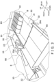
- the accumulation unit has a bottom portion and two inclined surfaces. The two inclined surfaces are disposed on both sides of the bottom portion as viewed from the front and rise upward from the bottom portion while inclining away from each other in directions away from the bottom portion.
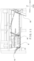
- FIG. 1 is a drawing showing the schematic configuration of a packaging and box packing line 1 including a box packing apparatus 300 pertaining to the embodiment.
- the packaging and box packing line 1 has a packaging machine 100, an inspection apparatus 200, and the box packing apparatus 300. It will be noted that FIG. 1 shows the box packing apparatus 300 covered by a cover.
- the packaging machine 100 packages, a predetermined quantity at a time in a packaging material, a product A manufactured by a manufacturing apparatus (not shown in the drawings). Articles that are obtained by packaging the product A in the packaging material will hereinafter be called bags B.
- the packaging machine 100 has a combination weighing machine 101 and a bagmaking and packaging machine 102.
- the combination weighing machine 101 is disposed above the bagmaking and packaging machine 102.
- the combination weighing machine 101 weighs a quantity of the product A to be put into one bag B and drops the product A to the bagmaking and packaging machine 102.
- the bagmaking and packaging machine 102 is a vertical pillow bagmaking and packaging machine, packages in bags B (vertical pillow bags) the product A weighed by the combination weighing machine 101, and supplies the bags B to the inspection apparatus 200.
- the product A is, for example, a snack food.
- the inspection apparatus 200 inspects the weights of, and whether or not there are pinholes and/or foreign matter in, the bags B supplied from the packaging machine 100 and supplies the bags B to the box packing apparatus 300.
- the box packing apparatus 300 executes a box packing operation in which it packs in a box C a predetermined accommodation number N of the bags B supplied from the inspection apparatus 200.
- the box packing apparatus 300 includes a conveyance unit 10, an alignment unit 20, a transfer unit 35, a contact unit 40, a drive unit 50, a gate 60, a pusher 70, a control unit 80, a first support unit 90, a second support unit 91, and a box conveyance unit 93.
- the conveyance unit 10 is a belt conveyor disposed such that a first conveyance direction 10d thereof is along the front and rear direction.
- the conveyance unit 10 configures a first conveyance route R1.
- the rear side of the conveyance unit 10 is upstream on the first conveyance route R1, and the front side of the conveyance unit 10 is downstream on the first conveyance route R1.
- the conveyance unit 10 is disposed in a plural number. In the present embodiment, two conveyance units 10 are disposed. The two conveyance units 10 are disposed such that first conveyance directions 10d thereof are parallel. The two conveyance units 10 are disposed so as to be bilaterally symmetrical to each other across the accumulation unit 30 and the gate 60 as viewed in a plan view. The two conveyance units 10 have the same structures except that they are bilaterally symmetrical.
- the conveyance unit 10 is controlled by the control unit 80.
- the conveyance unit 10 has an upper surface on which the bags B are placed and conveyed along the first conveyance direction 10d. On the upper surface of the conveyance unit 10, a plurality of the bags B are conveyed spaced apart from each other.
- the direction of the bags B is not particularly limited.
- the bags B may be conveyed such that the lengthwise direction of the bags B is along the first conveyance direction 10d.
- the conveyance unit 10 transfers the bags B to the alignment unit 20 at a predetermined timing. Specifically, the conveyance unit 10 transfers to the alignment unit 20 disposed under the conveyance unit 10 the bags B that have been conveyed to the vicinity of the first conveyance route R1 downstream end portion of the conveyance unit 10. The bags B are conveyed such that the up and down directions or the left and right directions of the plural bags B in the series all face the first conveyance direction 10d.
- the conveyance unit 10 may include plural belt conveyors.
- the conveyance unit 10 includes an infeed belt conveyor 11, a conveyance belt conveyor 12, and a discharge belt conveyor 13.
- the infeed belt conveyor 11 is disposed inclined relative to the horizontal direction.
- the infeed belt conveyor 11 feeds to the box packing apparatus 300 the bags B supplied from the inspection apparatus 200.
- the conveyance belt conveyor 12 forms a horizontal plane.
- the conveyance belt conveyor 12 receives the bags B from the infeed belt conveyor 11 and conveys them to the discharge belt conveyor 13.
- the discharge belt conveyor 13 is disposed inclined relative to a horizontal plane.
- the discharge belt conveyor 13 moves the bags B to the alignment unit 20.
- the alignment unit 20 is a belt conveyor disposed such that a second conveyance direction 20d thereof is along the front and rear direction.
- the second conveyance direction 20d faces the opposite direction of the first conveyance direction 10d.
- the alignment unit 20 configures a second conveyance route R2.
- the front side of the alignment unit 20 is upstream on the second conveyance route R2, and the rear side of the alignment unit 20 is downstream on the second conveyance route R2.
- the alignment unit 20 is disposed under the conveyance unit 10.
- the alignment unit 20 is disposed in a plural number. In the present embodiment, two alignment units 20 are disposed.
- the two alignment units 20 are disposed such that second conveyance directions 20d thereof are parallel.
- the two alignment units 20 are disposed so as to be bilaterally symmetrical to each other across the accumulation unit 30 and the gate 60 as viewed in a plan view.
- the two alignment units 20 have the same structures except that they are bilaterally symmetrical.
- the alignment unit 20 aligns the conveyed bags B in an overlapping formation so that the bags B that are mutually adjacent partially overlap to thereby form an article group B2, so called in Sashimi style.
- a first bag B is moved to the alignment unit 20.
- the moving method is not particularly limited.
- the bag B may be conveyed by the belt conveyors of the conveyance unit 10 and naturally drop from the first conveyance route R1 downstream end portion of the conveyance unit 10 to the alignment unit 20 positioned under the conveyance unit 10.
- the up and down direction or the left and right direction of the bag B relative to the first conveyance direction 10d does not change before or after the bag B naturally drops.
- the lengthwise direction of the bag B is along the second conveyance direction 20d.
- the first bag B that has been transferred to the alignment unit 20 is conveyed by the belt conveyor of the alignment unit 20 on the second conveyance route R2 in the second conveyance direction 20d.
- a next bag B is moved from the conveyance unit 10 to the alignment unit 20 so that it partially overlaps the first bag B that was conveyed.
- an article group B2 in which the bags B are aligned such that the bags B that are mutually adjacent partially overlap, is formed.
- the plural bags B are inclined in the same direction.
- the alignment unit 20 is controlled by the control unit 80 to control conveyance such that a predetermined number of the bags B are aligned.
- the article group B2 includes six bags B.
- the alignment unit 20 has a first alignment area 21, a second alignment area 22, a third alignment area 23, and an attitude changing member 24.
- the first alignment area 21, the second alignment area 22, and the third alignment area 23 are belt conveyors.
- the first alignment area 21 is disposed inclined relative to a horizontal plane.
- the first alignment area 21 receives the bags B that have been moved from the conveyance unit 10. Until it receives the predetermined number of the bags B, the first alignment area 21 is stopped or operates at a low speed. Because of this, the first alignment area 21 aligns the conveyed bags B so that the bags B that are mutually adjacent partially overlap to thereby form the article group B2.
- the second alignment area 22 is disposed inclined more gently than the first alignment area 21.
- the second alignment area 22 is disposed on the terminal end side of the first alignment area 21.
- the second alignment area 22 receives the article group B2 conveyed from the first alignment area 21.
- the second alignment area 22 operates in unison with the operation of the first alignment area 21.
- the third alignment area 23 is disposed on the terminal end side of the second alignment area 22.
- the third alignment area 23 forms a horizontal plane.
- the third alignment area 23 receives the article group B2 conveyed from the second alignment area 22.
- the alignment unit 20 can change the compression ratio of the article group B2 when it conveys the article group B2 to the third alignment area 23.
- the compression ratio is the ratio of the arrangement direction length, as viewed in a plan view, of the article group B2 in the aligned state to the shortest arrangement direction length, as viewed in a plan view, of the article group B2 aligned so that the bags B that are adjacent do not overlap.
- the method by which the alignment unit 20 changes the compression ratio of the article group B2 is not particularly limited.
- the alignment unit 20 may lower the compression ratio of the article group B2 by lengthening the operating time of the first alignment area 21.
- the alignment unit 20 conveys a first article group B2 to the third alignment area 23, it makes the compression ratio of that article group B2 higher than that of the trailing article group B2. Because of this, the first article group B2 is formed shorter in the front and rear direction than the trailing article group B2. As shown in FIG. 6 , when the alignment unit 20 conveys a second article group B2 to the third alignment area 23, it makes the compression ratio of that article group B2 lower than that of the first article group B2. Because of this, the second article group B2 is formed longer in the front and rear direction than the first article group B2. As a result, when the article groups B2 are moved by a side pusher 33 in a next process, the first article group B2 can be prevented from spreading in the shape of a fan.
- the attitude changing member 24 is disposed on the second conveyance direction 20d downstream end portion of the alignment unit 20.
- the attitude changing member 24 is a tabular member extending in the width direction of the alignment unit 20.
- the angle of the attitude changing member 24 relative to a horizontal plane can be changed.
- the attitude changing member 24 contacts the bag B that is most downstream in the second conveyance direction 20d in the article group B2.
- the angle of the contact surface of the attitude changing member 24 relative to a horizontal plane is increased to thereby raise the article group B2 so that the angle of the article group B2 relative to a horizontal plane becomes the same as or greater than the angle of the contact unit 40 relative to a horizontal plane. It will be noted that since the plural bags B are aligned in the article group B2, the angle of the article group B2 relative to a horizontal plane is the same as the angle of each bag B relative to a horizontal plane.
- the transfer unit 35 transfers the aligned article group B2 to a box packing conveyance route (hereinafter called a third conveyance route R3).
- the transfer unit 35 has an accumulation unit 30.
- the accumulation unit 30 is disposed between the two alignment units 20.
- the accumulation unit 30 is disposed such that left and right end portions of the accumulation unit 30 are at the same height as the third alignment areas 23 of the alignment units 20.
- the accumulation unit 30 transfers the aligned article group B2 and accumulates a plurality of the article groups B2 such that they are parallel to each other on the third conveyance route R3.
- the third conveyance route R3 includes the accumulation unit 30 and the gate 60.
- the rear side of the accumulation unit 30 is upstream on the third conveyance route R3, and the front side of the gate 60 is downstream on the third conveyance route R3.
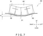
- the accumulation unit 30 has a bottom portion 31, two inclined surfaces 32, and a side pusher 33.
- the inclined surfaces 32 are disposed on both sides of the bottom portion 31, in other words on the left and right sides of the bottom portion 31, as viewed from the front.
- the inclined surfaces 32 rise upward from the bottom portion 31 while inclining away from each other in directions away from the bottom portion 31.
- the accumulation unit 30 is valley shaped.
- the angle of the inclined surfaces 32 relative to a horizontal plane is not particularly limited and is, for example, 5 to 10 degrees.
- the angle of the inclined surfaces 32 relative to a horizontal plane is 5 to 10 degrees, the article groups B2 can be prevented from going out of alignment when the article groups B2 are accumulated.
- the side pusher 33 is disposed one each on the outer sides of both the left and right edges of the third alignment areas 23 of the alignment units 20.
- Each side pusher 33 is a tabular member that extends parallel to the second conveyance direction 20d and is disposed perpendicular to a horizontal plane.
- the front and rear direction length of the side pusher 33 is the same as or shorter than the front and rear direction length of the third alignment area 23 of the alignment unit 20.
- the side pusher 33 can move the article group B2 in a direction perpendicular to the box packing conveyance direction (hereinafter called a third conveyance direction 30d).
- the third conveyance direction 30d faces the same direction as the first conveyance direction 10d.
- the third conveyance direction 30d faces the opposite direction of the second conveyance direction 20d.
- the side pushers 33 laterally move the article groups B2 in directions perpendicular to the third conveyance direction 30d while maintaining the aligned state of the article groups B2. Specifically, the side pushers 33 move the aligned article groups B2 from left and right toward the center portion of the accumulation unit 30 while staying parallel to the alignment unit 20.
- the side pushers 33 are controlled by the control unit 80.
- the side pushers 33 laterally move the first article groups B2, they return to their original positions, in other words the outer sides of both the left and right edges of the third alignment areas 23 of the alignment units 20.
- the next article groups B2 are delivered to the third alignment areas 23.
- the side pushers 33 similarly move the next article groups B2 toward the center portion of the accumulation unit 30.
- the accumulation unit 30 accumulates a plurality of the article groups B2 such that they are parallel to each other on the third conveyance route.
- the plural article groups B2 that have been accumulated by the accumulation unit 30 will hereinafter be called an accumulated article group B3.
- the accumulated article group B3 is accumulated in a state in which it is inclined 70 degrees relative to a horizontal plane.
- each side pusher 33 repeats this lateral movement of an article group B2 twice. Because of this, four article groups B2 become lined up parallel to each other on the accumulation unit 30 to form the accumulated article group B3.
- the contact unit 40 is disposed on the third conveyance direction 30d upstream end portion of the accumulation unit 30.
- the contact unit 40 is a tabular member extending in the left and right direction of the accumulation unit 30.
- the length of the accumulation unit 30 in its width direction (the left and right direction) is longer than the length of the contact unit 40 in its width direction (the left and right direction).
- the length of the accumulation unit 30 in its width direction is longer than the length of the contact unit 40 in its width direction (the left and right direction).
- the shape of the lower end of the contact unit 40 conforms to the shape of the upper surface of the accumulation unit 30.
- the lower end of the contact unit 40 is mountain shaped along the bottom portion 31 and the inclined surfaces 32 of the accumulation unit 30.
- the contact unit 40 is disposed inclined a predetermined angle relative to a horizontal plane.
- the contact unit 40 is, for example, disposed inclined 60 to 70 degrees relative to a horizontal plane.
- An angle formed by a contact surface of the contact unit 40 and a horizontal plane can be changed from a first angle A1 to a second angle A2.
- the second angle A2 is larger than the first angle A1.
- the angle formed by the contact surface of the contact unit 40 and a horizontal plane may be changed over multiple stages.
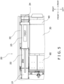
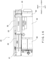
- FIG. 9 is a cross-sectional schematic drawing of the box packing apparatus 300 when the contact unit 40 has moved to the terminal end side of the accumulation unit 30.
- the contact unit 40 is movable along the third conveyance direction 30d.
- the contact unit 40 is driven by the drive unit 50 to move along the third conveyance direction 30d.
- the angle formed by the contact surface of the contact member 40 and a horizontal plane can be changed from the first angle A1 to the second angle A2 after the contact unit 40 starts moving along the third conveyance direction 30d.
- the moving speed of the contact unit 40 can be changed while the contact unit 40 is moving along the third conveyance direction 30d.
- the contact unit 40 is movable in the up and down direction.
- the contact unit 40 is driven by a cylinder 41 to move up and down.
- the method by which the contact unit 40 is moved in the up and down direction is not particularly limited and may, for example, use a cylinder.
- the contact unit 40 is movable in the shape of a box. That is, the contact unit 40 starts from the third conveyance direction 30d upstream end portion of the accumulation unit 30 and is driven by the drive unit 50 to move to the third conveyance direction 30d downstream end portion of the accumulation unit 30. Because of this, the accumulated article group B3 is conveyed to the gate 60. When it finishes this conveyance, the contact unit 40 is driven by the cylinder 41 to ascend. The height to which the contact unit 40 ascends is higher than the height of the bags B. In the ascended state, the contact unit 40 is driven by the drive unit 50 to move to the third conveyance direction 30d upstream side of the accumulation unit 30. The contact unit 40 is driven by the cylinder 41 to descend and returns to the start position.
- the contact unit 40 contacts the bags B that are on the third conveyance route most upstream side (the third conveyance route starting end side) in the accumulated article group B3. In other words, the contact unit 40 supports the bags B that were conveyed first by the alignment unit 20 out of each of the article groups B2. When a plurality of the article groups B2 are accumulated, the contact unit 40 collectively conveys the accumulated article group B3 in the third conveyance direction 30d to move it to the gate 60.
- the first support unit 90 is disposed on the third conveyance route upstream side of the accumulation unit 30.
- the first support unit 90 extends in the left and right direction of the accumulation unit 30.
- the first support unit 90 is movable in the up and down direction.
- the method by which the first support unit 90 is moved in the up and down direction is not particularly limited and may, for example, use a cylinder.
- the first support unit 90 does not move along the third conveyance direction 30d.
- the first support unit 90 is disposed inclined the same angle as the angle at which the contact unit 40 is inclined relative to a horizonal plane on the third conveyance direction 30d upstream side. Although it is not particularly limited, the first support unit 90 is, for example, disposed inclined 60 to 70 degrees relative to a horizontal plane.
- the first support unit 90 is controlled by the control unit 80.
- the first support unit 90 While the contact unit 40 is moving the first accumulated article group B3, the first support unit 90 supports the bags B that are on the third conveyance route most upstream side in the article group B3 that has been accumulated next. When the contact unit 40 returns to the third conveyance route most upstream side, the first support unit 90 descends so that the upper end of the first support unit 90 is positioned lower than the upper surface of the accumulation unit 30 to ensure that it does not hinder the movement of the contact unit 40 in the third conveyance direction 30d.
- the drive unit 50 drives the contact unit 40.
- the drive unit 50 is controlled by the control unit 80.
- the drive unit 50 is not particularly limited. In the present embodiment, the drive unit 50 is a belt.
- the drive unit 50 moves the contact unit 40 from the third conveyance direction upstream side of the accumulation unit 30 to the third conveyance direction downstream side.
- the drive unit 50 raises the contact unit 40 and moves it from the third conveyance direction downstream side of the accumulation unit 30 to the third conveyance direction upstream side.
- the drive unit 50 lowers the contact unit 40 to the back side of the first support unit 90, in other words the side opposite the accumulated article group B3.
- the second support unit 91 is disposed on the third conveyance direction downstream side of the gate 60.
- the second support unit 91 is a tabular member extending in the left and right direction of the gate 60.
- the second support unit 91 is disposed at a 90-degree angle relative to a horizontal plane. The angle of the second support unit 91 relative to a horizontal plane can be changed.
- the second support unit 91 is controlled by the control unit 80.
- the second support unit 91 contacts the bags B that are on the third conveyance route most downstream side.
- the bags B that are on the third conveyance route downstream side in the accumulated article group B3 may end up falling over due to inertia if the box packing apparatus 300 makes an emergency shutdown.
- the second support unit 91 inclines such that its angle relative to a horizontal plane is 45 degrees and waits for the accumulated article group B3.
- the second support unit 91 rises to 90 degrees relative to a horizontal plane and supports the bags B on the third conveyance route downstream side of the gate 60. Because of this, the bags B that are on the third conveyance route downstream side and had fallen over are raised so that their angle relative to a horizontal plane becomes the same as the angle of the other bags B relative to a horizontal plane, and the accumulated article group B3 can be packed without its aligned state being disrupted.
- the gate 60 is disposed on the third conveyance route downstream side of the accumulation unit 30.
- the gate 60 is positioned above a box packing position of the box conveyance unit 93.
- the gate 60 is positioned on the third conveyance route terminal end and supports the article group B3.
- the gate 60 is controlled by the control unit 80.
- the gate 60 feeds the article group B3 that has been transferred from the accumulation unit 30 into the box C. Just before being fed, the bags B of the article group B3 on the gate 60 are each standing upright perpendicular to a horizontal plane.
- the gate 60 opens in one go in the left and right directions from its center portion and collectively feeds the article group B3 into the box C.
- the operation of feeding the article group B3 into the box C may be performed multiple times with respect to one box C.
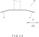
- the pusher 70 is disposed above the gate 60.
- the pusher 70 is movable in the up and down direction.
- the pusher 70 is a tabular member having a horizontal surface.
- the pusher 70 contacts the upper surface of the accumulated article group B3.
- the pusher 70 has downbent portions 71.
- the downbent portions 71 are bent down toward the bags B.
- the pusher 70 is controlled by the control unit 80.
- the pusher 70 contacts from above and pushes downward the accumulated article group B3 on the gate 60.
- the pusher 70 pushes downward the accumulated article group B3 at a speed faster than gravitational acceleration that acts on the accumulated article group B3.
- the pusher 70 collectively packs the article group B3.
- the box conveyance unit 93 performs infeed conveyance of the boxes C in which the bags B are not yet packed to the box packing position and outfeed conveyance of the boxes C in which the bags B have been packed.
- the box packing position is provided under the gate 60 so that the boxes C can receive the bags B fed thereto from the gate 60.
- the box conveyance unit 93 is controlled by the control unit 80.
- FIG. 14A is a block diagram of the control unit 80.
- the control unit 80 is electrically connected to, so as to be capable of sending control signals to and receiving detection signals from, the conveyance unit 10, the alignment unit 20, the accumulation unit 30, the contact unit 40, the drive unit 50, the gate 60, the pusher 70, the first support unit 90, the second support unit 91, and the box conveyance unit 93.
- the control unit 80 controls the drive unit 50 to move the contact unit 40 in the alignment direction of the accumulated article group B3 (the third conveyance direction 30d) in a state in which the contact unit 40 is contacting and supporting the bags B that are on the third conveyance route upstream side.
- the control unit 80 changes the angle formed by the contact surface of the contact unit 40 and a horizontal plane from the first angle A1 to the second angle A2 after the contact unit 40 starts moving the accumulated article group B3.
- the second angle is larger than the first angle. In the present embodiment, the first angle is 60 to 70 degrees. The second angle is 90 degrees.
- the control unit 80 may control the contact unit 40 to change over multiple stages the angle formed by the contact surface and a horizontal plane.
- the control unit 80 changes the angle formed by the contact surface of the contact unit 40 and a horizontal plane from the first angle A1 to the second angle A2 from when it starts moving the contact unit 40 to until it finishes moving the contact unit 40.
- the control unit 80 is realized by a computer.
- the control unit 80 includes a control arithmetic unit and a storage unit.
- a processor such as a CPU or a GPU can be used.
- the control arithmetic unit reads programs stored in the storage unit and performs predetermined arithmetic processing in accordance with the programs. Moreover, the control arithmetic unit can write arithmetic results to the storage unit and read information stored in the storage unit in accordance with the programs.
- the box packing operation is an operation that repeatedly packs the predetermined accommodation number N of the bags B in the boxes C. As shown in FIG. 14B , the box packing operation is started when, for example, the packaging and box packing line 1 starts up.
- the control unit 80 performs a box infeed conveyance process.
- the box infeed conveyance process is a process that conveys a box C to the box packing position.
- the box infeed conveyance process is a process where the box conveyance unit 93 conveys to the box packing position a box C in which the bags B are not yet packed.
- the control unit 80 causes the conveyance unit 10 to convey the bags B supplied from the inspection apparatus 200.
- the bags B are conveyed to the vicinity of the downstream end portion in the first conveyance direction 10d, the bags B are conveyed by the belt conveyors of the conveyance unit 10 and thus naturally drop from the downstream end portion of the conveyance unit 10 to the alignment unit 20 positioned under the conveyance unit 10.
- the control unit 80 causes the alignment unit 20 to align the bags B conveyed by the conveyance unit 10. Specifically, in the first alignment area 21 of the alignment unit 20, the next bag B is transferred to the alignment unit 20 such that it partially overlaps the first bag B that was conveyed.
- the control unit 80 controls the alignment unit 20 so that, when the alignment unit 20 conveys the first article group B2 to the third alignment area 23, it makes the compression ratio of that article group B2 higher than that of the trailing article group B2.
- the control unit 80 controls the attitude changing member 24 to causes the attitude changing member 24 to contact the bag B that is most downstream in the second conveyance direction 20d in the article group B2.
- the control unit 80 controls the attitude changing member 24 to increase the angle of the attitude changing member 24 relative to a horizontal plane to raise the article group B2 until the angle of the article group B2 relative to a horizontal plane becomes the same as the angle of the contact unit 40 relative to a horizontal plane.
- the control unit 80 causes the side pusher 33 to laterally move the article group B2 in a direction perpendicular to the box packing conveyance direction (the third conveyance direction 30d) while maintaining the aligned state of the article group B2. Because of this, the article group B2 is accumulated by the accumulation unit 30.
- the control unit 80 controls the drive unit 50 to move the contact unit 40 toward the third conveyance route R3 downstream side.
- the control unit 80 changes the angle formed by the contact surface of the contact unit 40 and a horizontal plane from the first angle A1 to the second angle A2 from when it starts moving the contact unit 40 to until it finishes moving the contact unit 40 in a state in which the contact unit 40 is contacting and supporting the bags B that are on the third conveyance route upstream side. Because of this, the contact unit 40 collectively moves onto the gate 60 the article group B3 that has been accumulated by the accumulation unit 30.
- the control unit 80 causes the side pusher 33 to return to its original position on the outer side of the alignment unit 20.
- control unit 80 While the control unit 80 is causing the contact unit 40 to move the first accumulated article group B3, it controls the first support unit 90 to cause the first support unit 90 to rise and support the second article group B3.
- the control unit 80 controls the drive unit 50 to raise the contact unit 40 and move it to the third conveyance route R3 upstream side.
- the contact unit 40 moves over the second accumulated article group B3 to the third conveyance route R3 upstream side.
- the control unit 80 lowers the contact unit 40 and causes the contact unit 40 to wait on the third conveyance route R3 upstream side of the first support unit 90.
- the control unit 80 lowers the first support unit 90. Because of this, the contact unit 40 supports the second accumulated article group B3.
- the control unit 80 drives the gate 60 and the pusher 70 to collectively pack the accumulated article group B3 in the box C positioned under the gate 60.
- the control unit 80 repeats the above series of box packing operations and judges whether a number Nn1 of the bags B that have been fed into the box C has reached a predetermined number Nfl.
- an accumulated article group B3 comprising twenty-four bags B is packed twice, so a total of forty-eight bags B are packed.
- the control unit 80 starts a box conveyance process.
- the box conveyance process is a process of conveying out the box C in which the bags B have been packed.
- the box packing apparatus 300 of the present embodiment includes the conveyance unit 10, the alignment unit 20, the transfer unit 35, the contact unit 40, the drive unit 50, and the control unit 80.
- the conveyance unit 10 conveys plural bags B from outside.
- the alignment unit 20 aligns the conveyed articles so that the articles that are mutually adjacent partially overlap to thereby form the article group B2.
- the transfer unit 35 transfers the aligned article group B2 to the third conveyance route R3.
- the contact unit 40 contacts the bags B that are on the box packing conveyance route upstream side in the transferred article group B2.
- the drive unit 50 drives the contact unit 40.
- the control unit 80 controls the drive unit 50 to move the contact unit 40 in the alignment direction of the article group B2 in a state in which the contact unit 40 is contacting and supporting the bags B that are on the third conveyance route R3 upstream side and changes the angle formed by the contact surface of the contact unit 40 and a horizontal plane from the first angle A1 to the second angle A2 larger than the first angle A1 after the contact unit 40 starts moving.
- control unit 80 changes the angle formed by the contact surface of the contact unit 40 and a horizontal plane from the first angle A1 to the second angle A2 from when it starts moving the contact unit 40 to until it finishes moving the contact unit 40.
- the transfer unit 35 laterally moves the article group B2 in a direction perpendicular to the conveyance direction while maintaining its aligned state.
- the aligned article group B2 can be collectively moved to the third conveyance route R3. For that reason, the amount of time it takes for the box packing work can be shortened.
- the alignment unit 20 and the conveyance unit 10 are each disposed in a plural number.
- the bags B can be conveyed and packed from the plural alignment units 20 and conveyance units 10, so the amount of time it takes for the box packing work can be shortened.
- the box packing apparatus 300 further includes the accumulation unit 30.
- the accumulation unit 30 accumulates a plurality of the article groups B2 such that they are parallel to each other on the third conveyance route R3.
- the accumulation unit 30 has the bottom portion 31 and the two inclined surfaces 32.
- the two inclined surfaces 32 are disposed on both sides of the bottom portion 31 as viewed from the front and rise upward from the bottom portion 31 while inclining away from each other in directions away from the bottom portion 31.
- the box packing apparatus 300 includes a plural number of the conveyance units 10 and a plural number of the alignment units 20, it is not particularly limited to this.
- the box packing apparatus 300 may include just one conveyance unit 10.
- the box packing apparatus 300 may include just one alignment unit 20.
- the box packing apparatus 300 includes just one alignment unit 20, four article groups B2 are moved from the one alignment unit 20 to the accumulation unit 30. In other words, the box packing apparatus 300 repeatedly moves an article group B2 from the alignment unit 20 to the accumulation unit 30 four times. At this time, the surfaces of the article groups B2 on the side pusher 33 side are inhibited by the side pusher 33 from spreading in front, rear, left, and right directions. However, the surfaces of the article groups B2 on the opposite side of the side pusher 33 are likely to spread forward, rearward, leftward, and rightward because there is nothing to inhibit them from spreading forward, rearward, leftward, and rightward.
- the alignment unit 20 when it conveys the article groups B2 to the third alignment area 23, the alignment unit 20 makes the compression ratio of the second article group B2 lower than the compression ratio of the first article group B2. As shown in FIG. 16 , the alignment unit 20 furthermore makes the compression ratio of the third article group B2 lower than the compression ratio of the second article group B2. The alignment unit 20 furthermore makes the compression ratio of the fourth article group B2 lower than the compression ratio of the third article group B2. In this way, when the side pusher 33 moves the article groups B2, as shown in FIG. 17 , the first article group B2 can be prevented from spreading in the shape of a fan.
- the accumulation unit 30 has the bottom portion 31 and the two inclined surfaces 32, it is not particularly limited to this.
- the accumulation unit 30 may also be V-shaped as viewed from the front.
- the accumulation unit 30 accumulates a plurality of the article groups B2, it is not particularly limited to this.
- the accumulation unit 30 may also accumulate just one article group B2.
- control unit 80 changes the angle formed by the contact surface of the contact unit 40 and a horizontal plane from the first angle A1 to the second angle A2 from when it starts moving the contact unit 40 to until it finishes moving the contact unit 40.
- the timing of the change from the first angle A1 to the second angle A2 is not particularly limited to this.
- control unit 80 may change the angle formed by the contact surface of the contact unit 40 and a horizontal plane from the first angle A1 to the second angle A2 after it finishes moving the contact unit 40.
- control unit 80 may change the angle formed by the contact surface of the contact unit 40 and a horizontal plane from the first angle A1 to the second angle A2 after a predetermined amount of time after it finishes moving the contact unit 40.
- the control unit 80 may change the angle formed by the contact surface of the contact unit 40 and a horizontal plane from the first angle A1 to the second angle A2 after the contact unit 40 has moved a predetermined distance after it finishes moving the contact unit 40.
- the accumulation unit 30 may have regulating portions 34.
- the regulating portions 34 are tabular members extending along the third conveyance direction 30d.
- the regulating portions 34 are disposed one each on both the left and right sides of the accumulation unit 30 as viewed from the front. Specifically, the regulating portions 34 are disposed on the outer edge portions of the inclined surfaces 32.
- the regulating portions 34 are disposed in positions higher than the bottom surfaces of the bags B of the accumulated article group B3.
- the regulating portions 34 are disposed at the same height as the third alignment areas 23 of the alignment units 20.
- the regulating portions 34 regulate the bags B of the accumulated article group B3 from spreading in the left and right direction.
- the article groups B2 When the article groups B2 have been laterally moved by the side pushers 33, the article groups B2 can cross over the regulating portions 34 and be accumulated by the accumulation unit 30. At the same time, the accumulated article group B3 does not return to the alignment units 20 because it is regulated on both left and right sides by the regulating portions 34.
- Patent Document 1 JP-U No. H6-3806
Landscapes
- Engineering & Computer Science (AREA)
- Mechanical Engineering (AREA)
- Container Filling Or Packaging Operations (AREA)
Applications Claiming Priority (1)
| Application Number | Priority Date | Filing Date | Title |
|---|---|---|---|
| JP2023195919A JP2025082528A (ja) | 2023-11-17 | 2023-11-17 | 箱詰装置 |
Publications (2)
| Publication Number | Publication Date |
|---|---|
| EP4556381A2 true EP4556381A2 (fr) | 2025-05-21 |
| EP4556381A3 EP4556381A3 (fr) | 2025-06-04 |
Family
ID=93432359
Family Applications (1)
| Application Number | Title | Priority Date | Filing Date |
|---|---|---|---|
| EP24211012.0A Pending EP4556381A3 (fr) | 2023-11-17 | 2024-11-05 | Appareil d'emballage de boîtes |
Country Status (4)
| Country | Link |
|---|---|
| US (1) | US12595085B2 (fr) |
| EP (1) | EP4556381A3 (fr) |
| JP (1) | JP2025082528A (fr) |
| CN (1) | CN120020056A (fr) |
Citations (1)
| Publication number | Priority date | Publication date | Assignee | Title |
|---|---|---|---|---|
| JPH063806U (ja) | 1992-06-24 | 1994-01-18 | 株式会社エヌエステイー | 菓子自動梱包装置 |
Family Cites Families (5)
| Publication number | Priority date | Publication date | Assignee | Title |
|---|---|---|---|---|
| FR1484885A (fr) * | 1966-06-20 | 1967-06-16 | Brecknell | Procédé et machine pour le groupement d'articles à emballer |
| US4864801A (en) * | 1988-03-30 | 1989-09-12 | Fallas David M | Automatic case packing apparatus |
| US5778640A (en) * | 1996-11-07 | 1998-07-14 | Blueprint Automation, Inc. | Apparatus and method for packing stand-up pouches into cartons |
| US7108155B2 (en) | 2002-11-04 | 2006-09-19 | Kimberly-Clark Worldwide, Inc. | Metering drum for an automatic accumulation system |
| US8646248B2 (en) * | 2009-02-16 | 2014-02-11 | Ishida Co., Ltd. | Packaging apparatus |
-
2023
- 2023-11-17 JP JP2023195919A patent/JP2025082528A/ja active Pending
-
2024
- 2024-11-01 CN CN202411552707.3A patent/CN120020056A/zh active Pending
- 2024-11-05 EP EP24211012.0A patent/EP4556381A3/fr active Pending
- 2024-11-14 US US18/948,344 patent/US12595085B2/en active Active
Patent Citations (1)
| Publication number | Priority date | Publication date | Assignee | Title |
|---|---|---|---|---|
| JPH063806U (ja) | 1992-06-24 | 1994-01-18 | 株式会社エヌエステイー | 菓子自動梱包装置 |
Also Published As
| Publication number | Publication date |
|---|---|
| JP2025082528A (ja) | 2025-05-29 |
| CN120020056A (zh) | 2025-05-20 |
| US12595085B2 (en) | 2026-04-07 |
| EP4556381A3 (fr) | 2025-06-04 |
| US20250162746A1 (en) | 2025-05-22 |
Similar Documents
| Publication | Publication Date | Title |
|---|---|---|
| CN102083694B (zh) | 成对包装生产线及计量系统 | |
| EP2060495A1 (fr) | Dispositif de transport, et dispositif et système d'emballage de boîte connexes | |
| EP1057728A1 (fr) | Machine pour trier et emballer des articles | |
| EP3663212B1 (fr) | Convertisseur de posture de chaîne de sacs et dispositif de mise en caisse | |
| JP6274708B2 (ja) | 分配搬送装置および分配搬送方法 | |
| EP4556381A2 (fr) | Appareil d'emballage de boîtes | |
| EP4566953A1 (fr) | Appareil d'emballage de boîtes | |
| JP3379912B2 (ja) | 物品の整列供給装置 | |
| EP4603398A1 (fr) | Dispositif de boxe | |
| JPH09502954A (ja) | 物品グループ内への仕切り挿入方法及び装置 | |
| JP2003300504A (ja) | 物品の箱詰装置 | |
| JPH0130423Y2 (fr) | ||
| JP6462556B2 (ja) | 箱詰め装置 | |
| US12319460B2 (en) | Box packing apparatus | |
| EP1310429A1 (fr) | Installation pour trier et emballer des articles | |
| JP2676036B2 (ja) | 生麺の容器詰め装置 | |
| KR102915493B1 (ko) | 고속 리니어 이송 장치를 이용한 필로우 포장 제품 집적장치 | |
| JPH04223920A (ja) | 一個送り出し搬送装置 | |
| JP2564261Y2 (ja) | 被包装物供給装置 | |
| JP3232436B2 (ja) | 定量詰め用のサイズ混合装置 | |
| JP2006248626A (ja) | 農産物用フリートレイの送出装置および農産物の選別包装装置 | |
| JPS586816A (ja) | 球状物処理機に於ける多列整列供給装置 | |
| JPH0597109A (ja) | 鶏卵の選別包装装置 | |
| JP2544024B2 (ja) | 作物の選別用搬送装置 | |
| JP2023130633A (ja) | 果菜排出方法、果菜箱詰め方法 |
Legal Events
| Date | Code | Title | Description |
|---|---|---|---|
| PUAI | Public reference made under article 153(3) epc to a published international application that has entered the european phase |
Free format text: ORIGINAL CODE: 0009012 |
|
| STAA | Information on the status of an ep patent application or granted ep patent |
Free format text: STATUS: REQUEST FOR EXAMINATION WAS MADE |
|
| PUAL | Search report despatched |
Free format text: ORIGINAL CODE: 0009013 |
|
| 17P | Request for examination filed |
Effective date: 20241105 |
|
| AK | Designated contracting states |
Kind code of ref document: A2 Designated state(s): AL AT BE BG CH CY CZ DE DK EE ES FI FR GB GR HR HU IE IS IT LI LT LU LV MC ME MK MT NL NO PL PT RO RS SE SI SK SM TR |
|
| AK | Designated contracting states |
Kind code of ref document: A3 Designated state(s): AL AT BE BG CH CY CZ DE DK EE ES FI FR GB GR HR HU IE IS IT LI LT LU LV MC ME MK MT NL NO PL PT RO RS SE SI SK SM TR |
|
| RIC1 | Information provided on ipc code assigned before grant |
Ipc: B65B 35/54 20060101ALI20250430BHEP Ipc: B65B 35/44 20060101ALI20250430BHEP Ipc: B65B 35/40 20060101ALI20250430BHEP Ipc: B65B 5/10 20060101ALI20250430BHEP Ipc: B65B 5/06 20060101AFI20250430BHEP |