EP4556839A1 - Wärmetauscher - Google Patents
Wärmetauscher Download PDFInfo
- Publication number
- EP4556839A1 EP4556839A1 EP24020329.9A EP24020329A EP4556839A1 EP 4556839 A1 EP4556839 A1 EP 4556839A1 EP 24020329 A EP24020329 A EP 24020329A EP 4556839 A1 EP4556839 A1 EP 4556839A1
- Authority
- EP
- European Patent Office
- Prior art keywords
- turbulising
- elements
- plates
- heat exchanger
- plate
- Prior art date
- Legal status (The legal status is an assumption and is not a legal conclusion. Google has not performed a legal analysis and makes no representation as to the accuracy of the status listed.)
- Pending
Links
Images

Classifications
-
- F—MECHANICAL ENGINEERING; LIGHTING; HEATING; WEAPONS; BLASTING
- F28—HEAT EXCHANGE IN GENERAL
- F28F—DETAILS OF HEAT-EXCHANGE AND HEAT-TRANSFER APPARATUS, OF GENERAL APPLICATION
- F28F3/00—Plate-like or laminated elements; Assemblies of plate-like or laminated elements
- F28F3/02—Elements or assemblies thereof with means for increasing heat-transfer area, e.g. with fins, with recesses, with corrugations
- F28F3/022—Elements or assemblies thereof with means for increasing heat-transfer area, e.g. with fins, with recesses, with corrugations the means being wires or pins
-
- B—PERFORMING OPERATIONS; TRANSPORTING
- B23—MACHINE TOOLS; METAL-WORKING NOT OTHERWISE PROVIDED FOR
- B23P—METAL-WORKING NOT OTHERWISE PROVIDED FOR; COMBINED OPERATIONS; UNIVERSAL MACHINE TOOLS
- B23P15/00—Making specific metal objects by operations not covered by a single other subclass or a group in this subclass
- B23P15/26—Making specific metal objects by operations not covered by a single other subclass or a group in this subclass heat exchangers or the like
-
- F—MECHANICAL ENGINEERING; LIGHTING; HEATING; WEAPONS; BLASTING
- F28—HEAT EXCHANGE IN GENERAL
- F28D—HEAT-EXCHANGE APPARATUS, NOT PROVIDED FOR IN ANOTHER SUBCLASS, IN WHICH THE HEAT-EXCHANGE MEDIA DO NOT COME INTO DIRECT CONTACT
- F28D9/00—Heat-exchange apparatus having stationary plate-like or laminated conduit assemblies for both heat-exchange media, the media being in contact with different sides of a conduit wall
- F28D9/0062—Heat-exchange apparatus having stationary plate-like or laminated conduit assemblies for both heat-exchange media, the media being in contact with different sides of a conduit wall the conduits for one heat-exchange medium being formed by spaced plates with inserted elements
- F28D9/0075—Heat-exchange apparatus having stationary plate-like or laminated conduit assemblies for both heat-exchange media, the media being in contact with different sides of a conduit wall the conduits for one heat-exchange medium being formed by spaced plates with inserted elements the plates having openings therein for circulation of the heat-exchange medium from one conduit to another
-
- F—MECHANICAL ENGINEERING; LIGHTING; HEATING; WEAPONS; BLASTING
- F28—HEAT EXCHANGE IN GENERAL
- F28F—DETAILS OF HEAT-EXCHANGE AND HEAT-TRANSFER APPARATUS, OF GENERAL APPLICATION
- F28F13/00—Arrangements for modifying heat-transfer, e.g. increasing, decreasing
- F28F13/06—Arrangements for modifying heat-transfer, e.g. increasing, decreasing by affecting the pattern of flow of the heat-exchange media
- F28F13/08—Arrangements for modifying heat-transfer, e.g. increasing, decreasing by affecting the pattern of flow of the heat-exchange media by varying the cross-section of the flow channels
-
- F—MECHANICAL ENGINEERING; LIGHTING; HEATING; WEAPONS; BLASTING
- F28—HEAT EXCHANGE IN GENERAL
- F28F—DETAILS OF HEAT-EXCHANGE AND HEAT-TRANSFER APPARATUS, OF GENERAL APPLICATION
- F28F3/00—Plate-like or laminated elements; Assemblies of plate-like or laminated elements
- F28F3/08—Elements constructed for building-up into stacks, e.g. capable of being taken apart for cleaning
-
- F—MECHANICAL ENGINEERING; LIGHTING; HEATING; WEAPONS; BLASTING
- F28—HEAT EXCHANGE IN GENERAL
- F28D—HEAT-EXCHANGE APPARATUS, NOT PROVIDED FOR IN ANOTHER SUBCLASS, IN WHICH THE HEAT-EXCHANGE MEDIA DO NOT COME INTO DIRECT CONTACT
- F28D9/00—Heat-exchange apparatus having stationary plate-like or laminated conduit assemblies for both heat-exchange media, the media being in contact with different sides of a conduit wall
- F28D9/0031—Heat-exchange apparatus having stationary plate-like or laminated conduit assemblies for both heat-exchange media, the media being in contact with different sides of a conduit wall the conduits for one heat-exchange medium being formed by paired plates touching each other
- F28D9/0043—Heat-exchange apparatus having stationary plate-like or laminated conduit assemblies for both heat-exchange media, the media being in contact with different sides of a conduit wall the conduits for one heat-exchange medium being formed by paired plates touching each other the plates having openings therein for circulation of at least one heat-exchange medium from one conduit to another
- F28D9/005—Heat-exchange apparatus having stationary plate-like or laminated conduit assemblies for both heat-exchange media, the media being in contact with different sides of a conduit wall the conduits for one heat-exchange medium being formed by paired plates touching each other the plates having openings therein for circulation of at least one heat-exchange medium from one conduit to another the plates having openings therein for both heat-exchange media
-
- F—MECHANICAL ENGINEERING; LIGHTING; HEATING; WEAPONS; BLASTING
- F28—HEAT EXCHANGE IN GENERAL
- F28F—DETAILS OF HEAT-EXCHANGE AND HEAT-TRANSFER APPARATUS, OF GENERAL APPLICATION
- F28F2250/00—Arrangements for modifying the flow of the heat exchange media, e.g. flow guiding means; Particular flow patterns
- F28F2250/02—Streamline-shaped elements
-
- F—MECHANICAL ENGINEERING; LIGHTING; HEATING; WEAPONS; BLASTING
- F28—HEAT EXCHANGE IN GENERAL
- F28F—DETAILS OF HEAT-EXCHANGE AND HEAT-TRANSFER APPARATUS, OF GENERAL APPLICATION
- F28F2250/00—Arrangements for modifying the flow of the heat exchange media, e.g. flow guiding means; Particular flow patterns
- F28F2250/10—Particular pattern of flow of the heat exchange media
- F28F2250/104—Particular pattern of flow of the heat exchange media with parallel flow
Definitions
- the invention concerns a heat exchanger.
- the invention is intended for energy-efficient devices and systems for generating and processing energy.
- heat exchangers which usually consist of a stack of plates fitted in a frame. Heat exchangers can be designed so that they ensure fluid countercurrent, cross, or co-current flow paths for hot and cold fluid streams.
- the known heat exchanger plates feature ducts for the flow of fluid, where the ducts are mounted on the plate surface, and where the streams of cold and hot fluid are isolated from each other.
- Known from patent document EP 4 130 627 A1 is a heat exchange system and a rib structure of a heat exchanger.
- the rib structure incorporates wavy ribs positioned parallel to one another at specified distances, thus forming ducts for the flow of the working agent.
- the ducts for the flow of the working agent are configured so that they can be used in the mode of both natural and forced heat transfer convection.
- EP 4 089 359 A1 is a heat exchanger plate fitted with numerous corrugations in the shape of ridges and grooves which form the flow paths along the plate surface, where the ridges and/or grooves are asymmetrical in shape with respect to the central ridge and/or groove line.
- the plates are set together to form a heat exchanger and can be bonded to one another permanently or detachably.
- the purpose of the present invention is to design a heat exchanger featuring structured heat exchange surface to be used in particular in plate heat exchangers working at high pressures and with fluids in supercritical state, capable of both intensifying heat exchange and strengthening heat exchanger structure which in turn results in reducing the amount of the necessary material.
- the invention solves the problem of reducing the size and weight of the plates intended for heat exchangers and thus reduces the size and weight of the heat exchangers which incorporate such plates and are designed for working at high pressures.
- the purpose was achieved by developing the shape of the turbulising elements, their size, and arrangement with respect to one another and to the flow of the working agent.
- a heat exchanger comprising plates which feature turbulising elements, where the said plates are arranged alternately into a packet so that the neighbouring plates are turned 180° with respect to each other in relation to the direction of the flow of the working agent through the plates, and where the turbulising elements of the specific plate contact the flat side of the neighbouring plate, and further where the packet is fitted with at least one inlet connection and at least one outlet connection for the first working agent, the connections fixed to the plates for the flow of the first agent, and is also fitted with at least one inlet connection and at least one outlet connection for the second working agent, the connections fixed to the plates for the flow of the second working agent, is characterized in that the turbulising elements of a specific plate contact the flat side of the neighbouring plate at the point where the turbulising elements of the neighbouring plate are positioned or at the point where some of the turbulising elements of the neighbouring plate are positioned, where the height of the turbulising elements in the plates for the first working agent is different than the height of
- the turbulising elements feature an arch-shaped side surface.
- the cross section of the turbulising elements has the shape of the aeronautical profile or ellipse, where preferably the width of the turbulising elements does not exceed 7mm and preferably the length of the turbulising elements does not exceed 15 mm.
- ⁇ width of the turbulising element' denotes the distance between the points in the cross section across the turbulising element (transversely to the direction of the flow of the working agent) which are found farthest apart.
- ⁇ length of the turbulising element' denotes the distance between the points in the cross section along the turbulising element (in line with the direction of the flow of the working agent) which are found farthest apart.
- the point of the maximum width of the turbulising elements falls no farther than 0.5 the length of the turbulising element when measuring from the leading edge, preferably at 0.10 the length.
- the turbulising elements can take the shape of a circle the diameter of which is preferably not larger than 15 mm.
- the turbulising elements are set in an arrangement based on an equilateral triangle so that the distance between the rows equals the height of the equilateral triangle the apexes of which are positioned at the ends of two neighbouring turbulising elements of the same row and at the respective end of the turbulising element positioned in the neighbouring row between the said turbulising elements.
- the height of the turbulising elements in any successive row is larger than that in the preceding row by the same value, or the height of the turbulising elements in any successive row is smaller than that in the preceding row by the same value.
- heat exchanger plates incorporate between 16000 and 39000 turbulising elements per 1 m 2 of the surface, not counting the turbulising elements.
- the turbulising elements are made of the same material as the plate body.
- the heat exchanger plate features a frame positioned along the perimeter of the plate.
- the heat exchanger according to the invention demonstrates many advantages compared to the known solutions.
- the geometry of the turbulising elements according to this invention enables fourfold intensification of the heat transfer coefficient compared to the known solutions, while retaining similar flow resistances.
- turbulising elements made of the same material as the plate body guarantees far better heat exchange in the exchanger, and the distribution of the turbulising elements without any defined ducts enables flow of the agent in various directions depending on the working mode of the exchanger.
- the weight and size of the heat exchanger according to this invention is much reduced compared to the standard heat exchangers available in the market, even by as much as 50%.
- turbulising elements 4 formed on one side of each of the plates 1A, 1B by e.g. the method of incremental laser printing using the same material as the material of the plate, i.e. powder SA-240 316L, where the turbulising elements 4 are arranged into rows so that turbulising elements 4 in the neighbouring rows of each of the plates 1A, 1B are positioned alternately to one another, and where turbulising elements 4 in all rows of each of the plates 1A, 1B are pointing in the same direction as the direction of the flow of the working agent.
- Turbulising elements 4 are distributed evenly on plates 1A, 1B in an arrangement based on the equilateral triangle the side of which is e.g.
- Turbulising elements 4 and frame 5 can be cut of a steel sheet and then the formed turbulising elements 4 and frame 5 can be placed on the surface of plates 1A, 1B, for example as described above, and bonded to the body of plates 1A, 1B by the diffusion bonding technology.
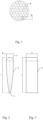
- the cross section of turbulising elements 4 takes the shape of the symmetrical aeronautical profile, as shown in Fig. 1 and
- the leading edge n of turbulising element 4 is given the shape of an arch
- the trailing edge s of turbulising element 4 is given the shape of an arch, where the radius of the trailing edge s is smaller than the radius of the leading edge n ( Fig. 2 ).
- the width b of turbulising elements 4 does not exceed 7 mm, in this particular embodiment being 1.2 mm, and their length l does not exceed 15 mm, in this particular embodiment being 6 mm.
- the point of the maximum width b of turbulising elements 4 falls at the distance of up to 0.5 the length l of turbulising element 4 measuring from the leading edge n, preferably at 0.10 the length l.
- the ratio of the maximum width b of turbulising element 4 and the length l is 1:5.
- Turbulising elements 4 on plates 1A, 1B are oriented so that their wider side faces the inflowing agent, i.e. in opposite directions for CO 2 and water, because of the opposite direction of their flow with respect to the length of the exchanger.
- the rib structure can incorporate between 16000 and 39000 turbulising elements per 1 m 2 of the surface, not counting the turbulising elements which occupy between 8% and 20% of the surface, respectively.
- the cross section of turbulising elements 4 is given the shape of a circle the diameter of which does not exceed 15 mm, or an ellipse the width of which does not exceed 7 mm and its length l does not exceed 15 mm.
- the cross section of the turbulising elements can be given the shape of any desired figure.
- the height h of turbulising elements 4 is the same in all rows ( Fig. 8 ), while in other embodiments the height h of turbulising elements 4 in any successive row is larger than that in the preceding row by the same value, and in yet another embodiment the height h of turbulising elements 4 in any successive row is smaller than that in the preceding row by the same value, always with respect to the direction of the flow of the working agent ( Fig. 9 ).
- the height h of turbulising elements 4 depends on the working agent and is 1 mm for CO 2 and 2 mm for water.
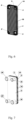
- frames 5 of plates 1A, 1B of the heat exchanger are 8 mm thick along the perimeter of openings 2, 2', 3, 3', and 3 mm elsewhere.
- the perimeter and shape of frames 5 is the same as the perimeters and shapes of plates 1A, 1B.
- Two openings 2, 2' or 3, 3', placed in the corners at the diagonal of each of the plates 1A, 1B, are blinded with an additional element of frame 5, which prevents mutual mixing of the working agents flowing through plates 1A, 1B.
- each of the frames 5 corresponds to the height h of the turbulising element 4 on the corresponding plate 1A and 1B. If the height h of turbulising elements 4 grows / diminishes along the length of plate 1A, 1B, the height of frame 5 increases/ decreases correspondingly to the increase/decrease of the height h of turbulising elements 4.
- So prepared frames 5 are put in place using assembly elements in the form of a stacking frame placed on each of the plates 1A, 1B, where the shape and dimensions of the stacking frame correspond to the shape and dimensions of plates 1A, 1B, which enables proper positioning of all elements found on each of the plates 1A, 1B, turbulising elements 4 included.
- An embodiment of the heat exchanger incorporates two types of plates 1A and 1B, in this variant specifically CO 2 plates and water plates.
- Each of the plates 1A, 1B features only two open openings 2, 2' or 3, 3' positioned on the opposite sides at the diagonal of each of the plates 1A, 1B. The other two openings are blanked.
- Opposite ducts blanked on the water plate are open on the CO 2 plate and vice-versa, i.e. the opposite ducts blanked on the CO 2 plate are open on the water plate.
- plates 1A, 1B are stacked alternately one on top of another ( Fig.
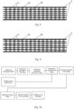
- the turbulising elements 4 of a specific plate 1A, 1B contact the flat side of the neighbouring plate 1A, 1B at the point where the turbulising elements 4 of the neighbouring plate 1A, 1B are situated ( Fig. 5 ), while in another embodiment the turbulising elements 4 of a specific plate 1A, 1B contact the flat side of the neighbouring plate 1A, 1B at the point where some of turbulising elements 4 of the plate are situated, i.e. with a slight mutual shift of turbulising elements 4 of the contacting plates 1A, 1B (not shown on the drawing).
- the heat exchanger is fitted with two closing plates 6 which are put in place on the top and bottom of the stack, also using a stacking frame.
- Closing plates 6 are 8 mm thick, they are made of the same material as the other elements of the heat exchanger, and their perimeters and shapes are the same as the perimeters and shapes of plates 1A, 1B of the heat exchanger.
- cut in each of end (closing) plates 6 are openings in the places corresponding to openings 2, 2', 3, 3' through which the corresponding agents are supplied and discharged.
- the bonding process is achieved at the temperature of 1050°C - 1070°C and lasts between 30 and 120 minutes. Diffusion bonding guarantees a permanent bond between the contacting elements of the heat exchanger. Following the bonding, the heat exchanger is subject to rapid cooling for 240 minutes.
- inlet and outlet connections 20, 20', 30, 30' for the working agents which enable the supply and discharge of the working agents to/from the heat exchanger.
- FIG. 10 A block diagram of a sample method of carrying out the heat exchanger is shown in Fig. 10 .
- the shape of the cross section of turbulising elements 4 in all plates 1A, 1B of the heat exchanger may be identical or different.
- the shape of turbulising elements 4 on a single plate 1A, 1B may be identical or different.
- frame 5 of plates 1A, 1B may be made by the incremental printing method using the same material as that used for the plate.
- Turbulising elements 4 may be cut from a steel sheet and then placed on the surface of plates 1A, 1B and bonded to the body of plates 1A, 1B, for example by the diffusion bonding or soldering method, or fixed in place by crimping on the plate surface, or formed by the incremental printing method.
- the circulation of the working agents in the solution according to this invention is as follows.
- the agent for example cold water
- supplied via inlet stub pipe 30 flows against plates 1A, while at the same time supplied via inlet stub pipe 20 in countercurrent to the direction of the flow of the water, is a hot working agent, for example supercritical carbon dioxide (sCO2) which flows against the plates 1B.
- sCO2 supercritical carbon dioxide
- the water flowing through plates A1 heats up, and the carbon dioxide flowing through plates 1B cools down.
- the heated water leaves the heat exchanger via outlet stub pipe 30', and the cooled carbon dioxide leaves the heat exchanger via outlet stub pipe 20'.
- the heat exchanger according to the invention can work in the temperature range from -200°C to +230°C and at any pressure of up to 150 bars.
Landscapes
- Engineering & Computer Science (AREA)
- Mechanical Engineering (AREA)
- Physics & Mathematics (AREA)
- Thermal Sciences (AREA)
- General Engineering & Computer Science (AREA)
- Heat-Exchange Devices With Radiators And Conduit Assemblies (AREA)
- Pressure Welding/Diffusion-Bonding (AREA)
Applications Claiming Priority (1)
| Application Number | Priority Date | Filing Date | Title |
|---|---|---|---|
| PL446756A PL446756A1 (pl) | 2023-11-17 | 2023-11-17 | Konstrukcja powierzchni wymiany ciepła, płyta wymiennika ciepła i sposób jej wytwarzania, oraz wymiennik ciepła |
Publications (1)
| Publication Number | Publication Date |
|---|---|
| EP4556839A1 true EP4556839A1 (de) | 2025-05-21 |
Family
ID=94083068
Family Applications (1)
| Application Number | Title | Priority Date | Filing Date |
|---|---|---|---|
| EP24020329.9A Pending EP4556839A1 (de) | 2023-11-17 | 2024-11-15 | Wärmetauscher |
Country Status (2)
| Country | Link |
|---|---|
| EP (1) | EP4556839A1 (de) |
| PL (1) | PL446756A1 (de) |
Citations (9)
| Publication number | Priority date | Publication date | Assignee | Title |
|---|---|---|---|---|
| GB2000268A (en) * | 1977-06-09 | 1979-01-04 | Ass Eng Ltd | Improvements in or relating to heat exchangers |
| US20090294113A1 (en) * | 2008-06-03 | 2009-12-03 | Korea Atomic Energy Research Institute | Heat exchanger |
| US20150122467A1 (en) * | 2012-05-29 | 2015-05-07 | Hangzhou Shenshi Energy Conservation Technology Co., Ltd. | Micro-channel structure for heat exchanger and integrated type micro-channel heat exchanger |
| CN105547019A (zh) * | 2015-12-15 | 2016-05-04 | 西安交通大学 | 一种非均匀分布肋片的高温高压板式换热器 |
| US20200141656A1 (en) * | 2018-11-01 | 2020-05-07 | Hamilton Sundstrand Corporation | Heat exchanger device |
| US20220011053A1 (en) | 2018-11-22 | 2022-01-13 | Sumitomo Precision Products Co., Ltd. | Diffusion Bonding Heat Exchanger |
| EP4089359A1 (de) | 2021-05-10 | 2022-11-16 | Danfoss A/S | Platte für plattenwärmetauscher mit asymmetrischen wellen |
| EP4130627A1 (de) | 2020-03-31 | 2023-02-08 | Sumitomo Precision Products Co., Ltd. | Wärmetauschersystem und rippenstruktur für wärmetauscher |
| CN114370777B (zh) * | 2021-11-30 | 2023-09-22 | 中国船舶重工集团公司第七一九研究所 | 印刷电路板换热器的换热通道结构及印刷电路板换热器 |
Family Cites Families (4)
| Publication number | Priority date | Publication date | Assignee | Title |
|---|---|---|---|---|
| ATE365901T1 (de) * | 2003-10-02 | 2007-07-15 | Hiflux Ltd | Wärmetauscher und verwendung davon |
| US7301770B2 (en) * | 2004-12-10 | 2007-11-27 | International Business Machines Corporation | Cooling apparatus, cooled electronic module, and methods of fabrication thereof employing thermally conductive, wire-bonded pin fins |
| US20090145581A1 (en) * | 2007-12-11 | 2009-06-11 | Paul Hoffman | Non-linear fin heat sink |
| CN107687780B (zh) * | 2017-08-05 | 2019-06-18 | 中国科学院工程热物理研究所 | 带有流线形肋结构的换热板及包含其的印刷电路板换热器 |
-
2023
- 2023-11-17 PL PL446756A patent/PL446756A1/pl unknown
-
2024
- 2024-11-15 EP EP24020329.9A patent/EP4556839A1/de active Pending
Patent Citations (9)
| Publication number | Priority date | Publication date | Assignee | Title |
|---|---|---|---|---|
| GB2000268A (en) * | 1977-06-09 | 1979-01-04 | Ass Eng Ltd | Improvements in or relating to heat exchangers |
| US20090294113A1 (en) * | 2008-06-03 | 2009-12-03 | Korea Atomic Energy Research Institute | Heat exchanger |
| US20150122467A1 (en) * | 2012-05-29 | 2015-05-07 | Hangzhou Shenshi Energy Conservation Technology Co., Ltd. | Micro-channel structure for heat exchanger and integrated type micro-channel heat exchanger |
| CN105547019A (zh) * | 2015-12-15 | 2016-05-04 | 西安交通大学 | 一种非均匀分布肋片的高温高压板式换热器 |
| US20200141656A1 (en) * | 2018-11-01 | 2020-05-07 | Hamilton Sundstrand Corporation | Heat exchanger device |
| US20220011053A1 (en) | 2018-11-22 | 2022-01-13 | Sumitomo Precision Products Co., Ltd. | Diffusion Bonding Heat Exchanger |
| EP4130627A1 (de) | 2020-03-31 | 2023-02-08 | Sumitomo Precision Products Co., Ltd. | Wärmetauschersystem und rippenstruktur für wärmetauscher |
| EP4089359A1 (de) | 2021-05-10 | 2022-11-16 | Danfoss A/S | Platte für plattenwärmetauscher mit asymmetrischen wellen |
| CN114370777B (zh) * | 2021-11-30 | 2023-09-22 | 中国船舶重工集团公司第七一九研究所 | 印刷电路板换热器的换热通道结构及印刷电路板换热器 |
Also Published As
| Publication number | Publication date |
|---|---|
| PL446756A1 (pl) | 2025-05-19 |
Similar Documents
| Publication | Publication Date | Title |
|---|---|---|
| EP2455695B1 (de) | Wärmetauscher | |
| JP3107597U (ja) | マイクロマルチチャンネル熱交換器のチューブ構造 | |
| US4665975A (en) | Plate type heat exchanger | |
| EP3306253B1 (de) | Wärmetauscherplatte und wärmetauscher | |
| US3291206A (en) | Heat exchanger plate | |
| JPS5928225Y2 (ja) | プレ−ト型熱交換器 | |
| KR102555230B1 (ko) | 상이한 온도를 갖는 유체들의 열교환을 위한 열교환기 | |
| US20120125583A1 (en) | Heat exchanger | |
| DK1794529T3 (en) | Heat exchanger with recess pattern | |
| RU2722078C1 (ru) | Теплопередающая пластина и теплообменник, содержащий множество таких теплопередающих пластин | |
| EP2584301A1 (de) | Hochtemperatur-Wärmeübertrager | |
| JP2000314596A (ja) | 蒸発器 | |
| EP4556839A1 (de) | Wärmetauscher | |
| JP2003021486A (ja) | 熱交換器 | |
| KR101579540B1 (ko) | 열교환 효율이 향상된 마이크로 가스터빈을 위한 주전열면을 구비한 열교환판, 및 이를 이용한 열교환기 | |
| EP1007893B1 (de) | Wärmetauscherwirbelerzeuger mit unterbrochenen wellungen | |
| JP2025531925A (ja) | 熱交換器モジュール | |
| CN213120209U (zh) | 一种高效烟气板式余热回收器用换热器 | |
| JP2003185376A (ja) | 冷却液/空気熱交換器コアアセンブリ | |
| JP2008249168A (ja) | 熱交換器 | |
| CN214371969U (zh) | 一种间隔支撑件及其盘管热交换器 | |
| US20230117804A1 (en) | Plate heat exchanger | |
| WO1988002092A1 (en) | Heat exchangers | |
| CN116817646A (zh) | 交叉流混合式印刷电路板式换热器 | |
| CN219572764U (zh) | 钎焊换热器 |
Legal Events
| Date | Code | Title | Description |
|---|---|---|---|
| PUAI | Public reference made under article 153(3) epc to a published international application that has entered the european phase |
Free format text: ORIGINAL CODE: 0009012 |
|
| STAA | Information on the status of an ep patent application or granted ep patent |
Free format text: STATUS: THE APPLICATION HAS BEEN PUBLISHED |
|
| AK | Designated contracting states |
Kind code of ref document: A1 Designated state(s): AL AT BE BG CH CY CZ DE DK EE ES FI FR GB GR HR HU IE IS IT LI LT LU LV MC ME MK MT NL NO PL PT RO RS SE SI SK SM TR |
|
| STAA | Information on the status of an ep patent application or granted ep patent |
Free format text: STATUS: REQUEST FOR EXAMINATION WAS MADE |
|
| 17P | Request for examination filed |
Effective date: 20251119 |
|
| GRAP | Despatch of communication of intention to grant a patent |
Free format text: ORIGINAL CODE: EPIDOSNIGR1 |
|
| STAA | Information on the status of an ep patent application or granted ep patent |
Free format text: STATUS: GRANT OF PATENT IS INTENDED |
|
| INTG | Intention to grant announced |
Effective date: 20260326 |
|
| RAP3 | Party data changed (applicant data changed or rights of an application transferred) |
Owner name: AIC SPOLKA AKCYJNA |