EP4560186A1 - Beleuchtungsvorrichtung für fahrzeugscheinwerfer - Google Patents
Beleuchtungsvorrichtung für fahrzeugscheinwerfer Download PDFInfo
- Publication number
- EP4560186A1 EP4560186A1 EP23212201.0A EP23212201A EP4560186A1 EP 4560186 A1 EP4560186 A1 EP 4560186A1 EP 23212201 A EP23212201 A EP 23212201A EP 4560186 A1 EP4560186 A1 EP 4560186A1
- Authority
- EP
- European Patent Office
- Prior art keywords
- shutter
- illumination device
- shutter body
- edge
- angular range
- Prior art date
- Legal status (The legal status is an assumption and is not a legal conclusion. Google has not performed a legal analysis and makes no representation as to the accuracy of the status listed.)
- Pending
Links
Images



Classifications
-
- F—MECHANICAL ENGINEERING; LIGHTING; HEATING; WEAPONS; BLASTING
- F21—LIGHTING
- F21S—NON-PORTABLE LIGHTING DEVICES; SYSTEMS THEREOF; VEHICLE LIGHTING DEVICES SPECIALLY ADAPTED FOR VEHICLE EXTERIORS
- F21S41/00—Illuminating devices specially adapted for vehicle exteriors, e.g. headlamps
- F21S41/60—Illuminating devices specially adapted for vehicle exteriors, e.g. headlamps characterised by a variable light distribution
- F21S41/68—Illuminating devices specially adapted for vehicle exteriors, e.g. headlamps characterised by a variable light distribution by acting on screens
- F21S41/683—Illuminating devices specially adapted for vehicle exteriors, e.g. headlamps characterised by a variable light distribution by acting on screens by moving screens
-
- F—MECHANICAL ENGINEERING; LIGHTING; HEATING; WEAPONS; BLASTING
- F21—LIGHTING
- F21S—NON-PORTABLE LIGHTING DEVICES; SYSTEMS THEREOF; VEHICLE LIGHTING DEVICES SPECIALLY ADAPTED FOR VEHICLE EXTERIORS
- F21S41/00—Illuminating devices specially adapted for vehicle exteriors, e.g. headlamps
- F21S41/10—Illuminating devices specially adapted for vehicle exteriors, e.g. headlamps characterised by the light source
- F21S41/14—Illuminating devices specially adapted for vehicle exteriors, e.g. headlamps characterised by the light source characterised by the type of light source
- F21S41/141—Light emitting diodes [LED]
- F21S41/143—Light emitting diodes [LED] the main emission direction of the LED being parallel to the optical axis of the illuminating device
-
- F—MECHANICAL ENGINEERING; LIGHTING; HEATING; WEAPONS; BLASTING
- F21—LIGHTING
- F21S—NON-PORTABLE LIGHTING DEVICES; SYSTEMS THEREOF; VEHICLE LIGHTING DEVICES SPECIALLY ADAPTED FOR VEHICLE EXTERIORS
- F21S41/00—Illuminating devices specially adapted for vehicle exteriors, e.g. headlamps
- F21S41/20—Illuminating devices specially adapted for vehicle exteriors, e.g. headlamps characterised by refractors, transparent cover plates, light guides or filters
- F21S41/25—Projection lenses
-
- F—MECHANICAL ENGINEERING; LIGHTING; HEATING; WEAPONS; BLASTING
- F21—LIGHTING
- F21S—NON-PORTABLE LIGHTING DEVICES; SYSTEMS THEREOF; VEHICLE LIGHTING DEVICES SPECIALLY ADAPTED FOR VEHICLE EXTERIORS
- F21S41/00—Illuminating devices specially adapted for vehicle exteriors, e.g. headlamps
- F21S41/60—Illuminating devices specially adapted for vehicle exteriors, e.g. headlamps characterised by a variable light distribution
- F21S41/68—Illuminating devices specially adapted for vehicle exteriors, e.g. headlamps characterised by a variable light distribution by acting on screens
- F21S41/683—Illuminating devices specially adapted for vehicle exteriors, e.g. headlamps characterised by a variable light distribution by acting on screens by moving screens
- F21S41/686—Blades, i.e. screens moving in a vertical plane
-
- B—PERFORMING OPERATIONS; TRANSPORTING
- B60—VEHICLES IN GENERAL
- B60Q—ARRANGEMENT OF SIGNALLING OR LIGHTING DEVICES, THE MOUNTING OR SUPPORTING THEREOF OR CIRCUITS THEREFOR, FOR VEHICLES IN GENERAL
- B60Q2300/00—Indexing codes for automatically adjustable headlamps or automatically dimmable headlamps
- B60Q2300/10—Indexing codes relating to particular vehicle conditions
- B60Q2300/13—Attitude of the vehicle body
- B60Q2300/136—Roll
-
- F—MECHANICAL ENGINEERING; LIGHTING; HEATING; WEAPONS; BLASTING
- F21—LIGHTING
- F21S—NON-PORTABLE LIGHTING DEVICES; SYSTEMS THEREOF; VEHICLE LIGHTING DEVICES SPECIALLY ADAPTED FOR VEHICLE EXTERIORS
- F21S41/00—Illuminating devices specially adapted for vehicle exteriors, e.g. headlamps
- F21S41/20—Illuminating devices specially adapted for vehicle exteriors, e.g. headlamps characterised by refractors, transparent cover plates, light guides or filters
- F21S41/25—Projection lenses
- F21S41/255—Lenses with a front view of circular or truncated circular outline
-
- F—MECHANICAL ENGINEERING; LIGHTING; HEATING; WEAPONS; BLASTING
- F21—LIGHTING
- F21W—INDEXING SCHEME ASSOCIATED WITH SUBCLASSES F21K, F21L, F21S and F21V, RELATING TO USES OR APPLICATIONS OF LIGHTING DEVICES OR SYSTEMS
- F21W2102/00—Exterior vehicle lighting devices for illuminating purposes
- F21W2102/10—Arrangement or contour of the emitted light
- F21W2102/13—Arrangement or contour of the emitted light for high-beam region or low-beam region
- F21W2102/135—Arrangement or contour of the emitted light for high-beam region or low-beam region the light having cut-off lines, i.e. clear borderlines between emitted regions and dark regions
-
- F—MECHANICAL ENGINEERING; LIGHTING; HEATING; WEAPONS; BLASTING
- F21—LIGHTING
- F21W—INDEXING SCHEME ASSOCIATED WITH SUBCLASSES F21K, F21L, F21S and F21V, RELATING TO USES OR APPLICATIONS OF LIGHTING DEVICES OR SYSTEMS
- F21W2107/00—Use or application of lighting devices on or in particular types of vehicles
- F21W2107/10—Use or application of lighting devices on or in particular types of vehicles for land vehicles
- F21W2107/13—Use or application of lighting devices on or in particular types of vehicles for land vehicles for cycles
-
- F—MECHANICAL ENGINEERING; LIGHTING; HEATING; WEAPONS; BLASTING
- F21—LIGHTING
- F21W—INDEXING SCHEME ASSOCIATED WITH SUBCLASSES F21K, F21L, F21S and F21V, RELATING TO USES OR APPLICATIONS OF LIGHTING DEVICES OR SYSTEMS
- F21W2107/00—Use or application of lighting devices on or in particular types of vehicles
- F21W2107/10—Use or application of lighting devices on or in particular types of vehicles for land vehicles
- F21W2107/13—Use or application of lighting devices on or in particular types of vehicles for land vehicles for cycles
- F21W2107/17—Use or application of lighting devices on or in particular types of vehicles for land vehicles for cycles for motorcycles
Definitions
- the invention relates to an illumination device for vehicle headlamps, especially for single-track vehicle headlamps, in particular for motorcycle headlamps, wherein the illumination device is configured to form a light distribution with a cut-off line and comprises:
- a headlight that is rigidly connected with the motorcycle or with the fork of the motorcycle can no longer illuminate the roadway in front of the motorcycle in an optimum fashion.
- the invention is basically suitable for every vehicle that experience inclination during cornering.
- the setup of the light distribution in particular a low beam distribution, is prescribed by law and measured on the vehicle standing straight.
- the vehicle tilts with the headlamp or the illumination device about the longitudinal axis of the vehicle.
- the shutter device is formed of:
- the first and second shutter body are rotatable independently and relative to each other about the common rotation axis.
- the first shutter body comprises a first part-circular gliding surface complementary to a first counter circular gliding surface of the holder, wherein the first shutter body engages with the holder so as the first part-circular gliding surface and the first counter circular gliding surface can glide on one another.
- the second shutter body comprises a second part-circular gliding surface complementary to a second counter circular gliding surface of the holder, wherein the second shutter body engages with the holder so as the second part-circular gliding surface and the second counter circular gliding surface can glide on one another.
- the rotation device comprises a transmission element formed as a toothed wheel configured to engage with a toothed array of the first and/or second shutter body in order to convert an angular motion of the transmission element into an rotation motion of the first and/or second shutter body around the common rotation axis.
- each shutter body comprises a toothed array, which is sectionally arranged on the first part-circular gliding surface on the first shutter body, sectionally arranged on the second part-circular gliding surface of the second shutter body.
- the first and second shutter body are mechanically connectable via at least one connection device, wherein the connection device comprises a first and second engaging element, and wherein the first and second engaging element are connectable to each other such that when connected, the connection device limits the rotation of the first and second shutter body relative to each other around the common rotation axis.
- the first engaging element is arranged on the first or second shutter body and the second engaging element is arranged on the second or first shutter body.
- the first engaging element is built as a groove and the second engaging element is built as a protrusion, wherein the groove has two opposite ends, and wherein the relative motion of the first and second shutter body to each other is restricted when the protrusion abuts on the respective ends of the groove
- the transmission element is rotatable in different angular ranges starting from a zero position in which the common shutter edge of the shutter device is straight and horizontal - seen in a correctly installed state of the illumination device in a vehicle -, wherein
- the first angular range is from 0° to 6°
- the second angular range is from 6° to 12°
- the third angular range starts from 12°.
- the first and second shutter plane is 3° to 5°, preferably 4°, tilted away from the optical axis.
- the at least one light source is mounted on the holder.
- the illumination device comprises a plurality of light sources, preferably a plurality of LEDs, wherein preferably for each light source at least one collimator element configured to collimate light is assigned to it.
- the main direction is parallel to the optical axis, preferably also to the common rotation axis.
- the shutter device comprises a reset element configured to bring the first and second shutter body from a maximum tilt in a non-aligned position to an aligned position.
- the reset element is formed as a spring.
- the spring comprises a first and second arm.
- the first shutter body comprises a first reset holder configured to hold the first arm of the spring
- the second shutter body comprises a second reset holder configured to hold the second arm of the spring
- the spring is not spring-loaded when the shutter device is in the zero position.
- the first and/or second shutter body comprises at least one weight element configured to support the respective shutter body into a zero position.
- a stabilized illumination device for irradiating a stabilized light distribution, comprising at least one illumination device according to the invention, an external control unit and at least one roll angle sensor configured to determine a roll angle from a defined standard position of the illumination device around the main direction, said external control unit is configured to frequently, preferably constantly, receive a roll angle from the at least one roll angle sensor and to control the transmission element depending on the roll angle in order to maintain a stabilized light distribution.
- a motor cycle headlamp comprising at least one illumination device according to the invention and/or at least one stabilized illumination device according to the invention.
- Fig. 1A shows an illumination device 10 for vehicle headlamps, especially for single-track vehicle headlamps, in particular for motorcycle headlamps, wherein the illumination device 10 is configured to form a light distribution with a cut-off line.
- the illumination device 10 comprises light sources 20 configured to emit light in a main direction X for forming the light distribution.
- the light sources are LEDs, wherein preferably for each light source 20 at least one collimator element configured to collimate light is assigned to it.
- the illumination device 10 comprises a shutter device 100 arranged downstream of the light sources 20 along the main direction X, wherein the shutter device 100 is configured to generate the cut-off line in the light distribution.
- the illumination device 10 comprises a projection lens 200 for projecting the generated light distribution of the light sources 20 in conjunction with the shutter device 100 in front of the illumination device 10, wherein the projection lens 200 comprises an optical axis A.
- the illumination device 10 comprises a holder 300 configured to hold the shutter device 100 and the projection lens 200, also the light sources 20 are mounted on the holder 300.
- the shutter device 100 is formed of a first shutter body 110 with a first shutter plane 110a comprising a first shutter edge 110b, and a second shutter body 120 with a second shutter plane 120a comprising a second shutter edge 120b.
- the first and second shutter plane 110a, 120a is 3° to 5°, preferably 4°, tilted away from the optical axis A.
- the first and second shutter body 110, 120 are arranged to one another that the first and second shutter edge 110b, 120b together build a common shutter edge 150, which generates the cut-off line in the light distribution.
- the shutter device 100 is configured to transition between aligned positions of the first and second shutter edge 110b, 120b, wherein the common shutter edge 150 contributes to generate a straight cut-off line, and non-aligned positions of the first and second shutter edge 110b, 120b, wherein the first and second shutter edge 110b, 120b are inclined with respect to each other, so that the common shutter edge 150 contributes to generate a cut-off line deviating from a straight cut-off line.
- the transition between the positions is performed by rotation of the first and/or second shutter body 110, 120 about a common rotation axis R by means of a rotation device 400, wherein the first and second shutter body 110, 120 are rotatable independently and relative to each other about the common rotation axis R.
- the main direction X is parallel to the optical axis A, preferably also to the common rotation axis R.
- the first shutter body 110 comprises a first part-circular gliding surface 111 complementary to a first counter circular gliding surface 310 of the holder 300, wherein the first shutter body 110 engages with the holder 300 so as the first part-circular gliding surface 111 and the first counter circular gliding surface 310 can glide on one another.
- the second shutter body 120 comprises a second part-circular gliding surface 121 complementary to a second counter circular gliding surface 320 of the holder 300, wherein the second shutter body 120 engages with the holder 300 so as the second part-circular gliding surface 121 and the second counter circular gliding surface 320 can glide on one another, as can be seen in Fig. 1A and Fig. 1B .
- the shutter device 100 comprises a reset element 600 configured to bring the first and second shutter body 110, 120 from a maximum tilt in a non-aligned position to an aligned position.
- the reset element 600 is formed as a spring and is arranged between the first and second shutter body 110, 120.
- the reset element 600 comprises a first and second arm, wherein first shutter body 110 comprises a first reset holder 610 configured to hold the first arm of the spring, and wherein the second shutter body 120 comprises a second reset holder 620 configured to hold the second arm of the spring, as can be seen in Fig. 2A and Fig. 2B .
- the rotation device 400 comprises a transmission element 410 formed as a toothed wheel configured to engage with a toothed array 130 of the first and/or second shutter body 110, 120 in order to convert an angular motion of the transmission element 410 into a rotation motion of the first and/or second shutter body 110, 120 around the common rotation axis R.
- a transmission element 410 formed as a toothed wheel configured to engage with a toothed array 130 of the first and/or second shutter body 110, 120 in order to convert an angular motion of the transmission element 410 into a rotation motion of the first and/or second shutter body 110, 120 around the common rotation axis R.
- the toothed array 130 which is arranged on each shutter body 110, 120.
- the shutter device 100 is in a zero position in which the common shutter edge 150 of the shutter device 100 is straight and horizontal - seen in a correctly installed state of the illumination device in a vehicle, and wherein the toothed arrays 130 of the shutter bodies 110, 120 overlaps to some degree.
- the transmission element 410 engages with the toothed arrays 130 of both shutter bodies 110, 120, whereas and wherein the reset element 600 is not spring-loaded when the shutter device 100 is in the zero position.
- first and second shutter body 110, 120 are mechanically connectable via at least one connection device 500, wherein the connection device 500 comprises a first and second engaging element 510, 520, and wherein the first and second engaging element 510, 520 are connectable to each other such that when connected, the connection device 500 limits the rotation of the first and second shutter body 110, 120 relative to each other around the common rotation axis R.
- the first engaging element 510 is arranged on the second shutter body 120 and the second engaging element 520 is arranged on the first shutter body 110.
- the first engaging element 510 is built as a groove and the second engaging element 520 is built as a protrusion, wherein the groove has two opposite ends, and wherein the relative motion of the first and second shutter body 110, 120 to each other is restricted when the protrusion abuts on the respective ends of the groove as best can be seen in Fig. 1B and Fig. 5A to Fig. 5D .
- the transmission element 410 is rotatable in different angular ranges AR1, AR2, AR3 starting from the zero position in which the common shutter edge 150 of the shutter device 100 is straight and horizontal - seen in a correctly installed state of the illumination device in a vehicle, wherein in a first angular range AR1 the transmission element 410 engages with the first and second shutter body 110, 120 in a way that both shutter bodies 110, 120 are moved together around the common rotational axis R and are in aligned positions.
- a second angular range AR2 - starting from the end of the first angular range AR1 - the transmission element 410 engages with the shutter bodies 110, 120 in a way that only the second shutter body 120 is moved by the transmission element 410 causing non-aligned positions of the first and second shutter body 110, 120, wherein the second angular range AR2 ends when the connection device 500 restricts the relative rotation of the first and second shutter body 110,120 to each other.
- the first angular range AR1 ranges from 0° to 6°
- the second angular range AR2 from 6° to 12°
- the third angular range AR3 starts from 12°.
- Fig. 4A shows a front view of the illumination device 10 without the projection lens 200, wherein the shutter device 100 is in the zero position, and wherein the mentioned angular ranges AR1, AR2, AR3 are indicated.
- Fig. 4B the shutter device 100 is shown in a tilted manner within the first angular range AR1, or to be specific, at the end of the first angular range AR1, wherein the shutter device 100 is still in an aligned position. To obtain this position, the transmission element 410 was - seen in this front view - rotated counter-clockwise.
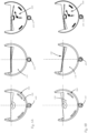
- Fig. 5A which shows a back view, front view and a middle view, where one can see the spring 600, respectively, wherein the shutter device 100 is in the zero position.
- Fig. 5B shows the same views, but the shutter device 100 is tilted via the transmission element 410 in the first angular range AR1 - as already introduced in Fig. 4A and Fig. 4B , wherein the spring 600 is not spring-loaded. This position is achieved by rotating the transmission element 410 - seen in the front view - counter clockwise. In the zero position, the transmission element 410 engages with the toothed arrays 130 of both shutter bodies 110, 120 (shown in Fig. 3A and Fig.
- both toothed arrays 130 are overlapping as can be seen in Fig. 3B , enabling the tilting of both shutter bodies 110, 120 in the same manner. Also, in the first angular range AR1, the spring 600 is not spring-loaded.
- the transmission element 410 - seen in the front view - is rotated further counter-clockwise causing only the second shutter body 120 to rotate as the transmission element 410 is only engaging with the toothed array 130 of the second shutter body 120 at the end of the first angular range AR1 (or the beginning of the second angular range AR2 ) .
- the spring 600 is spring-loaded, wherein the second angular range AR2 ends when the connection device 500 restricts the relative rotation of the first and second shutter body 110, 120 to each other, as can be seen in Fig. 5C .
- the transmission element 410 - seen in the front view - is rotated further counter-clockwise, the transmission element 410 engages with the shutter bodies 110, 120 in a way that only the second shutter body 110 is moved by the transmission element 410, wherein the first shutter body 120 is rotated around the common rotation axis R to the same extent by means of the connection device 500 - the spring 600 is still spring-loaded.
- the spring 600 assists to bring the shutter bodies 110, 120 back into an aligned position.
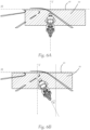
- Fig. 6A and Fig. 6B shows a motor vehicle on a street, wherein the motor vehicle comprises a stabilized illumination device for irradiating a stabilized light distribution 30, comprising an abovementioned illumination device, an external control unit and at least one roll angle sensor configured to determine a roll angle ⁇ from a defined standard position of the illumination device or the motor vehicle around the main direction X, said external control unit is configured to frequently, preferably constantly, receive a roll angle ⁇ from the at least one roll angle sensor and to control the transmission element 410 depending on the roll angle in order to maintain a stabilized light distribution or to adjust the light distribution depending on the roll angle ⁇ .
- the motor vehicle comprises a stabilized illumination device for irradiating a stabilized light distribution 30, comprising an abovementioned illumination device, an external control unit and at least one roll angle sensor configured to determine a roll angle ⁇ from a defined standard position of the illumination device or the motor vehicle around the main direction X, said external control unit is configured to frequently, preferably constantly, receive
- Fig. 6A the motor vehicle is in a standard position - therefore the illumination device 10 - and projects a light distribution 30 with a straight and horizontal cut-off line 40 onto the street.
- the shutter device 100 of the illumination device 10 is in the zero position.
- Fig. 6B the motor cycle inclines to a roll angle ⁇ greater than zero, wherein the horizontal alignment of the light distribution 30 is maintained, so that the cut-off line 40 maintains in a straight horizontal line.
- LIST OF REFERENCE SIGNS Illumination device comprising: 10 Light sources... 20 Light distribution... 30 Cut-off line... 40
- Shutter device 100 First shutter body... 110 First shutter plane... 110a First shutter edge... 110b First part circular gliding surface... 111 Second shutter body... 120 Second shutter plane... 120a Second shutter edge... 120b Second part circular gliding surface... 121 Common shutter edge... 150 Projection lens... 200 Holder... 300 First counter circular gliding surface... 310 Second counter circular gliding surface... 320 Rotation device... 400 Transmission element... 410 Connection device...
Landscapes
- Engineering & Computer Science (AREA)
- General Engineering & Computer Science (AREA)
- Physics & Mathematics (AREA)
- Microelectronics & Electronic Packaging (AREA)
- Optics & Photonics (AREA)
- Non-Portable Lighting Devices Or Systems Thereof (AREA)
- Chemical & Material Sciences (AREA)
- Crystallography & Structural Chemistry (AREA)
Priority Applications (3)
| Application Number | Priority Date | Filing Date | Title |
|---|---|---|---|
| EP23212201.0A EP4560186A1 (de) | 2023-11-27 | 2023-11-27 | Beleuchtungsvorrichtung für fahrzeugscheinwerfer |
| JP2024187435A JP7862509B2 (ja) | 2023-11-27 | 2024-10-24 | 自動車前照灯の照明装置 |
| US18/953,241 US12510223B2 (en) | 2023-11-27 | 2024-11-20 | Illumination device for vehicle headlamps |
Applications Claiming Priority (1)
| Application Number | Priority Date | Filing Date | Title |
|---|---|---|---|
| EP23212201.0A EP4560186A1 (de) | 2023-11-27 | 2023-11-27 | Beleuchtungsvorrichtung für fahrzeugscheinwerfer |
Publications (1)
| Publication Number | Publication Date |
|---|---|
| EP4560186A1 true EP4560186A1 (de) | 2025-05-28 |
Family
ID=88975570
Family Applications (1)
| Application Number | Title | Priority Date | Filing Date |
|---|---|---|---|
| EP23212201.0A Pending EP4560186A1 (de) | 2023-11-27 | 2023-11-27 | Beleuchtungsvorrichtung für fahrzeugscheinwerfer |
Country Status (2)
| Country | Link |
|---|---|
| US (1) | US12510223B2 (de) |
| EP (1) | EP4560186A1 (de) |
Citations (11)
| Publication number | Priority date | Publication date | Assignee | Title |
|---|---|---|---|---|
| JPH0384504U (de) * | 1989-12-20 | 1991-08-27 | ||
| US5113319A (en) * | 1989-11-28 | 1992-05-12 | Stanley Electric Co. Ltd. | Head lamp for cornering operation |
| DE4102586C2 (de) * | 1990-01-31 | 2000-07-06 | Honda Motor Co Ltd | Scheinwerfer |
| EP1201989A2 (de) * | 2000-10-25 | 2002-05-02 | Zizala Lichtsysteme GmbH | Fahrzeugscheinwerfer |
| DE10335952B4 (de) * | 2002-08-13 | 2004-12-23 | Baier, Karl, Dipl.-Ing. | Scheinwerfer |
| JP2010061985A (ja) * | 2008-09-03 | 2010-03-18 | Koito Mfg Co Ltd | 車両用前照灯 |
| US20110110113A1 (en) * | 2009-11-10 | 2011-05-12 | Hung Kwan-Ten | Control device of a headlamp's high and low beam |
| US8113700B2 (en) * | 2009-11-10 | 2012-02-14 | Raiderson Enterprise Co., Ltd. | Headlamp with high and low beam control device |
| CN202691916U (zh) * | 2012-04-12 | 2013-01-23 | 雷家祥 | 车灯光线调整装置 |
| JP2013032127A (ja) * | 2011-08-03 | 2013-02-14 | Koito Mfg Co Ltd | 二輪車用ヘッドランプ |
| US20140145612A1 (en) * | 2011-07-13 | 2014-05-29 | Toyota Jidosha Kabushiki Kaisha | Vehicle light distribution control device and vehicle light distribution control method |
-
2023
- 2023-11-27 EP EP23212201.0A patent/EP4560186A1/de active Pending
-
2024
- 2024-11-20 US US18/953,241 patent/US12510223B2/en active Active
Patent Citations (11)
| Publication number | Priority date | Publication date | Assignee | Title |
|---|---|---|---|---|
| US5113319A (en) * | 1989-11-28 | 1992-05-12 | Stanley Electric Co. Ltd. | Head lamp for cornering operation |
| JPH0384504U (de) * | 1989-12-20 | 1991-08-27 | ||
| DE4102586C2 (de) * | 1990-01-31 | 2000-07-06 | Honda Motor Co Ltd | Scheinwerfer |
| EP1201989A2 (de) * | 2000-10-25 | 2002-05-02 | Zizala Lichtsysteme GmbH | Fahrzeugscheinwerfer |
| DE10335952B4 (de) * | 2002-08-13 | 2004-12-23 | Baier, Karl, Dipl.-Ing. | Scheinwerfer |
| JP2010061985A (ja) * | 2008-09-03 | 2010-03-18 | Koito Mfg Co Ltd | 車両用前照灯 |
| US20110110113A1 (en) * | 2009-11-10 | 2011-05-12 | Hung Kwan-Ten | Control device of a headlamp's high and low beam |
| US8113700B2 (en) * | 2009-11-10 | 2012-02-14 | Raiderson Enterprise Co., Ltd. | Headlamp with high and low beam control device |
| US20140145612A1 (en) * | 2011-07-13 | 2014-05-29 | Toyota Jidosha Kabushiki Kaisha | Vehicle light distribution control device and vehicle light distribution control method |
| JP2013032127A (ja) * | 2011-08-03 | 2013-02-14 | Koito Mfg Co Ltd | 二輪車用ヘッドランプ |
| CN202691916U (zh) * | 2012-04-12 | 2013-01-23 | 雷家祥 | 车灯光线调整装置 |
Also Published As
| Publication number | Publication date |
|---|---|
| JP2025093862A (ja) | 2025-06-24 |
| US20250172269A1 (en) | 2025-05-29 |
| US12510223B2 (en) | 2025-12-30 |
Similar Documents
| Publication | Publication Date | Title |
|---|---|---|
| ES2259185T3 (es) | Faro para vehiculos. | |
| JP6161732B2 (ja) | 前照灯装置 | |
| KR102337496B1 (ko) | 모듈 구성형 자동차 헤드램프 광 모듈 | |
| JPH0762962B2 (ja) | 車輌用前照灯 | |
| CN102563546B (zh) | 车辆用灯具的控制装置、系统及控制方法 | |
| CN111336467B (zh) | 车辆前灯的照明装置 | |
| JP7688765B2 (ja) | 車両用灯具および車両システム | |
| US11420550B2 (en) | Adjusting system for pivoting at least one optically relevant component of a vehicle headlight about a first and a second axis | |
| CN111336468B (zh) | 用于车辆前照灯的照明装置 | |
| JP2832748B2 (ja) | 自動車の前照灯位置調節装置 | |
| JP2000090721A (ja) | 車両用前照灯 | |
| JP2014191996A (ja) | 車両用灯具ユニット | |
| US12510223B2 (en) | Illumination device for vehicle headlamps | |
| JP2832548B2 (ja) | 車両用前照灯 | |
| JP7862509B2 (ja) | 自動車前照灯の照明装置 | |
| JP3207526B2 (ja) | プロジェクタランプのリフレクタ駆動機構 | |
| JPH06176604A (ja) | 配光可変型プロジェクタランプのリフレクタ駆動機構 | |
| JPH06176603A (ja) | 配光可変型プロジェクタランプのレンズ駆動機構 | |
| JPH083922Y2 (ja) | 配光可変型前照灯のレンズ駆動機構 | |
| JPH0720801Y2 (ja) | 拡散角度可変型ランプ装置 | |
| JPS63312280A (ja) | 二輪車用ヘッドランプ | |
| JPH0729404A (ja) | リフレクタ駆動式車両用配光可変型灯具 | |
| JPS63151591A (ja) | 車輌用前照灯の照射角修正装置 | |
| JPH067102U (ja) | プロジェクタランプのリフレクタ駆動機構 | |
| JPH0652702A (ja) | リフレクタ可動型プロジェクタランプ |
Legal Events
| Date | Code | Title | Description |
|---|---|---|---|
| PUAI | Public reference made under article 153(3) epc to a published international application that has entered the european phase |
Free format text: ORIGINAL CODE: 0009012 |
|
| STAA | Information on the status of an ep patent application or granted ep patent |
Free format text: STATUS: THE APPLICATION HAS BEEN PUBLISHED |
|
| AK | Designated contracting states |
Kind code of ref document: A1 Designated state(s): AL AT BE BG CH CY CZ DE DK EE ES FI FR GB GR HR HU IE IS IT LI LT LU LV MC ME MK MT NL NO PL PT RO RS SE SI SK SM TR |
|
| STAA | Information on the status of an ep patent application or granted ep patent |
Free format text: STATUS: REQUEST FOR EXAMINATION WAS MADE |
|
| 17P | Request for examination filed |
Effective date: 20251111 |
|
| RIC1 | Information provided on ipc code assigned before grant |
Ipc: F21S 41/683 20180101AFI20260304BHEP Ipc: F21S 41/686 20180101ALI20260304BHEP Ipc: F21W 102/135 20180101ALN20260304BHEP Ipc: F21W 107/17 20180101ALN20260304BHEP |
|
| GRAP | Despatch of communication of intention to grant a patent |
Free format text: ORIGINAL CODE: EPIDOSNIGR1 |
|
| STAA | Information on the status of an ep patent application or granted ep patent |
Free format text: STATUS: GRANT OF PATENT IS INTENDED |
|
| GRAS | Grant fee paid |
Free format text: ORIGINAL CODE: EPIDOSNIGR3 |
|
| GRAA | (expected) grant |
Free format text: ORIGINAL CODE: 0009210 |
|
| STAA | Information on the status of an ep patent application or granted ep patent |
Free format text: STATUS: THE PATENT HAS BEEN GRANTED |