EP4563325A1 - Dispositif de contrôle pour contrôler au moins une préforme, machine d'étirage-soufflage et procédé de contrôle d'une préforme - Google Patents
Dispositif de contrôle pour contrôler au moins une préforme, machine d'étirage-soufflage et procédé de contrôle d'une préforme Download PDFInfo
- Publication number
- EP4563325A1 EP4563325A1 EP24209837.4A EP24209837A EP4563325A1 EP 4563325 A1 EP4563325 A1 EP 4563325A1 EP 24209837 A EP24209837 A EP 24209837A EP 4563325 A1 EP4563325 A1 EP 4563325A1
- Authority
- EP
- European Patent Office
- Prior art keywords
- preform
- testing device
- evaluation unit
- sensor data
- test criterion
- Prior art date
- Legal status (The legal status is an assumption and is not a legal conclusion. Google has not performed a legal analysis and makes no representation as to the accuracy of the status listed.)
- Granted
Links
Images

Classifications
-
- B—PERFORMING OPERATIONS; TRANSPORTING
- B29—WORKING OF PLASTICS; WORKING OF SUBSTANCES IN A PLASTIC STATE IN GENERAL
- B29C—SHAPING OR JOINING OF PLASTICS; SHAPING OF MATERIAL IN A PLASTIC STATE, NOT OTHERWISE PROVIDED FOR; AFTER-TREATMENT OF THE SHAPED PRODUCTS, e.g. REPAIRING
- B29C49/00—Blow-moulding, i.e. blowing a preform or parison to a desired shape within a mould; Apparatus therefor
- B29C49/42—Component parts, details or accessories; Auxiliary operations
- B29C49/78—Measuring, controlling or regulating
-
- G—PHYSICS
- G01—MEASURING; TESTING
- G01N—INVESTIGATING OR ANALYSING MATERIALS BY DETERMINING THEIR CHEMICAL OR PHYSICAL PROPERTIES
- G01N21/00—Investigating or analysing materials by the use of optical means, i.e. using sub-millimetre waves, infrared, visible or ultraviolet light
- G01N21/84—Systems specially adapted for particular applications
- G01N21/88—Investigating the presence of flaws or contamination
- G01N21/90—Investigating the presence of flaws or contamination in a container or its contents
- G01N21/9081—Inspection especially designed for plastic containers, e.g. preforms
-
- B—PERFORMING OPERATIONS; TRANSPORTING
- B29—WORKING OF PLASTICS; WORKING OF SUBSTANCES IN A PLASTIC STATE IN GENERAL
- B29C—SHAPING OR JOINING OF PLASTICS; SHAPING OF MATERIAL IN A PLASTIC STATE, NOT OTHERWISE PROVIDED FOR; AFTER-TREATMENT OF THE SHAPED PRODUCTS, e.g. REPAIRING
- B29C49/00—Blow-moulding, i.e. blowing a preform or parison to a desired shape within a mould; Apparatus therefor
- B29C49/42—Component parts, details or accessories; Auxiliary operations
- B29C49/78—Measuring, controlling or regulating
- B29C2049/787—Thickness
-
- B—PERFORMING OPERATIONS; TRANSPORTING
- B29—WORKING OF PLASTICS; WORKING OF SUBSTANCES IN A PLASTIC STATE IN GENERAL
- B29C—SHAPING OR JOINING OF PLASTICS; SHAPING OF MATERIAL IN A PLASTIC STATE, NOT OTHERWISE PROVIDED FOR; AFTER-TREATMENT OF THE SHAPED PRODUCTS, e.g. REPAIRING
- B29C49/00—Blow-moulding, i.e. blowing a preform or parison to a desired shape within a mould; Apparatus therefor
- B29C49/42—Component parts, details or accessories; Auxiliary operations
- B29C49/78—Measuring, controlling or regulating
- B29C2049/7874—Preform or article shape, weight, defect or presence
-
- B—PERFORMING OPERATIONS; TRANSPORTING
- B29—WORKING OF PLASTICS; WORKING OF SUBSTANCES IN A PLASTIC STATE IN GENERAL
- B29C—SHAPING OR JOINING OF PLASTICS; SHAPING OF MATERIAL IN A PLASTIC STATE, NOT OTHERWISE PROVIDED FOR; AFTER-TREATMENT OF THE SHAPED PRODUCTS, e.g. REPAIRING
- B29C49/00—Blow-moulding, i.e. blowing a preform or parison to a desired shape within a mould; Apparatus therefor
- B29C49/42—Component parts, details or accessories; Auxiliary operations
- B29C49/78—Measuring, controlling or regulating
- B29C2049/7874—Preform or article shape, weight, defect or presence
- B29C2049/7875—Size or shape
-
- B—PERFORMING OPERATIONS; TRANSPORTING
- B29—WORKING OF PLASTICS; WORKING OF SUBSTANCES IN A PLASTIC STATE IN GENERAL
- B29C—SHAPING OR JOINING OF PLASTICS; SHAPING OF MATERIAL IN A PLASTIC STATE, NOT OTHERWISE PROVIDED FOR; AFTER-TREATMENT OF THE SHAPED PRODUCTS, e.g. REPAIRING
- B29C49/00—Blow-moulding, i.e. blowing a preform or parison to a desired shape within a mould; Apparatus therefor
- B29C49/42—Component parts, details or accessories; Auxiliary operations
- B29C49/78—Measuring, controlling or regulating
- B29C2049/7874—Preform or article shape, weight, defect or presence
- B29C2049/7876—Defects
-
- B—PERFORMING OPERATIONS; TRANSPORTING
- B29—WORKING OF PLASTICS; WORKING OF SUBSTANCES IN A PLASTIC STATE IN GENERAL
- B29C—SHAPING OR JOINING OF PLASTICS; SHAPING OF MATERIAL IN A PLASTIC STATE, NOT OTHERWISE PROVIDED FOR; AFTER-TREATMENT OF THE SHAPED PRODUCTS, e.g. REPAIRING
- B29C49/00—Blow-moulding, i.e. blowing a preform or parison to a desired shape within a mould; Apparatus therefor
- B29C49/42—Component parts, details or accessories; Auxiliary operations
- B29C49/78—Measuring, controlling or regulating
- B29C2049/788—Controller type or interface
- B29C2049/78805—Computer or PLC control
-
- B—PERFORMING OPERATIONS; TRANSPORTING
- B29—WORKING OF PLASTICS; WORKING OF SUBSTANCES IN A PLASTIC STATE IN GENERAL
- B29C—SHAPING OR JOINING OF PLASTICS; SHAPING OF MATERIAL IN A PLASTIC STATE, NOT OTHERWISE PROVIDED FOR; AFTER-TREATMENT OF THE SHAPED PRODUCTS, e.g. REPAIRING
- B29C2949/00—Indexing scheme relating to blow-moulding
- B29C2949/07—Preforms or parisons characterised by their configuration
- B29C2949/0715—Preforms or parisons characterised by their configuration the preform having one end closed
-
- B—PERFORMING OPERATIONS; TRANSPORTING
- B29—WORKING OF PLASTICS; WORKING OF SUBSTANCES IN A PLASTIC STATE IN GENERAL
- B29C—SHAPING OR JOINING OF PLASTICS; SHAPING OF MATERIAL IN A PLASTIC STATE, NOT OTHERWISE PROVIDED FOR; AFTER-TREATMENT OF THE SHAPED PRODUCTS, e.g. REPAIRING
- B29C49/00—Blow-moulding, i.e. blowing a preform or parison to a desired shape within a mould; Apparatus therefor
- B29C49/02—Combined blow-moulding and manufacture of the preform or the parison
- B29C49/06—Injection blow-moulding
-
- B—PERFORMING OPERATIONS; TRANSPORTING
- B29—WORKING OF PLASTICS; WORKING OF SUBSTANCES IN A PLASTIC STATE IN GENERAL
- B29C—SHAPING OR JOINING OF PLASTICS; SHAPING OF MATERIAL IN A PLASTIC STATE, NOT OTHERWISE PROVIDED FOR; AFTER-TREATMENT OF THE SHAPED PRODUCTS, e.g. REPAIRING
- B29C49/00—Blow-moulding, i.e. blowing a preform or parison to a desired shape within a mould; Apparatus therefor
- B29C49/42—Component parts, details or accessories; Auxiliary operations
- B29C49/42378—Handling malfunction
- B29C49/4238—Ejecting defective preforms or products
-
- B—PERFORMING OPERATIONS; TRANSPORTING
- B29—WORKING OF PLASTICS; WORKING OF SUBSTANCES IN A PLASTIC STATE IN GENERAL
- B29C—SHAPING OR JOINING OF PLASTICS; SHAPING OF MATERIAL IN A PLASTIC STATE, NOT OTHERWISE PROVIDED FOR; AFTER-TREATMENT OF THE SHAPED PRODUCTS, e.g. REPAIRING
- B29C49/00—Blow-moulding, i.e. blowing a preform or parison to a desired shape within a mould; Apparatus therefor
- B29C49/42—Component parts, details or accessories; Auxiliary operations
- B29C49/64—Heating or cooling preforms, parisons or blown articles
- B29C49/6409—Thermal conditioning of preforms
-
- B—PERFORMING OPERATIONS; TRANSPORTING
- B29—WORKING OF PLASTICS; WORKING OF SUBSTANCES IN A PLASTIC STATE IN GENERAL
- B29K—INDEXING SCHEME ASSOCIATED WITH SUBCLASSES B29B, B29C OR B29D, RELATING TO MOULDING MATERIALS OR TO MATERIALS FOR MOULDS, REINFORCEMENTS, FILLERS OR PREFORMED PARTS, e.g. INSERTS
- B29K2067/00—Use of polyesters or derivatives thereof, as moulding material
- B29K2067/003—PET, i.e. poylethylene terephthalate
-
- B—PERFORMING OPERATIONS; TRANSPORTING
- B29—WORKING OF PLASTICS; WORKING OF SUBSTANCES IN A PLASTIC STATE IN GENERAL
- B29L—INDEXING SCHEME ASSOCIATED WITH SUBCLASS B29C, RELATING TO PARTICULAR ARTICLES
- B29L2031/00—Other particular articles
- B29L2031/712—Containers; Packaging elements or accessories, Packages
- B29L2031/7158—Bottles
Definitions
- the invention relates to a testing device for testing a preform, a stretch blow molding machine and a method for testing a preform.
- Preforms are generally pre-formed materials that are frequently used as preliminary products in the prior art and processed into a final product in a final production step.
- One production process that shapes preforms into hollow bodies is the stretch blow molding process, also called the blow molding process.
- the stretch blow molding process is used to produce plastic containers, in particular bottles, from thermoplastics in particular.
- the preform which is in particular a pre-formed plastic sleeve, is heated to a processing temperature of preferably 90°C to 120°C.
- the preforms generally have a functional area for holding them in a preheating area. In preforms used for bottle production, the functional area is preferably integrated into a support ring of a threaded neck.
- the preform is inserted into a blow mold.
- a stretch rod is guided into the preform and the preform is stretched in a longitudinal direction.
- a process gas is introduced into the preform, causing the preform to expand in a transverse and/or longitudinal direction until the outer walls of the preform are in contact with the walls of the blow mold.
- Blow molding processes are known that initially apply a first pressure of the process gas and then a second pressure of the process gas.
- the preform is vented. formed hollow body and ejecting the formed hollow body from the blow mold.
- Various quality assurance methods are known in the prior art which determine the quality of a preform based on test criteria.
- sensors are used in particular to test the quality of the preform.
- a first sensor is used to query the height of a support ring.
- a second sensor is usually used to verify the wobble.
- a third sensor is used in the prior art to monitor the attachment of the preform in a preform holder.
- a fourth sensor in particular a camera, is used in the prior art to inspect the side walls of the preform.
- a fifth sensor in particular a second camera
- a sixth sensor in particular a third camera
- a fifth sensor is used in the prior art to check the color of the preform
- a sixth sensor in particular a third camera
- checking the test criteria during a heating phase of the preform is known in the prior art.
- the quality of a preform can be checked before expansion. This allows preforms that do not meet quality requirements to be removed from the process before expansion.
- WO 00 2020 177 982 A1 discloses a method for product guidance in a stretch blow molding and/or filling system for bottles and a corresponding production system. Accordingly, blank parameters of blanks prepared for stretch blow molding are automatically measured, and the resulting initial data is stored. Furthermore, at least bottle parameters of stretch-blown empty and/or subsequently filled bottles are automatically measured and, optionally, machine faults occurring during stretch blow molding and/or filling are also automatically detected. The resulting data are individually assigned to the blanks and saved. Furthermore, at least one rejection criterion subsequently applicable in production for deciding on the rejection of defective blanks or bottles is calculated based on a data analysis of the saved initial data.
- rejection criterion is also automatically updated, taking into account the initial data and result data acquired during production, product quality can be continuously improved by processing an increasingly large amount of data in the sense of self-optimization, and the frequency of production downtimes can be reduced.
- DE 000010 259 589 B3 discloses a method and apparatus for producing hollow plastic bodies by insert blow molding heated preforms, wherein the preforms are inspected before heating and at least some of the defective preforms are heated and only rejected after heating.
- an optoelectronic inspection station is disclosed, arranged in front of a rotating area of the inlet star wheel, with a CCD camera arranged stationary above the path of movement of the preforms, having an optical system and an illumination device. The camera generates an image of the neck and the support ring of each passing preform. The image is analyzed and classified in real time in a connected electronic evaluation device.
- a first error signal is generated, and a second error signal is generated when a preform with a strongly oval or closed or only partially open neck is inspected, regardless of whether the sealing surface and the support ring are damaged or not.
- the current state of the art has the disadvantage that a large number of sensors and cameras are used to inspect the preform.
- the associated test setup is complex. High-quality testing is essential to ensure high production standards. Consequently, there is a need for an improved testing facility for verifying a variety of geometry-related and material-related test criteria for preforms, particularly those intended for stretch blow molding.
- the object of the invention is to improve the state of the art.
- a testing device for testing at least one preform comprising an optical sensor, an evaluation unit with a data input and a data output, wherein the evaluation unit is connected to the optical sensor via the data input so as to exchange sensor data
- the testing device is assigned a holding device which is designed to hold the preform and guides the preform to a first position in a first predefined orientation of the preform at a first point in time and guides the preform to a second position in a second predefined orientation of the preform at a second point in time
- the testing device is configured to determine first sensor data of the preform by means of the optical sensor at the first point in time and to send it to the evaluation unit via the data input and to determine second sensor data of the preform by means of the optical sensor at the second point in time and to send it to the evaluation unit via the data input
- the evaluation unit is configured to determine compliance with a first test criterion based on the first sensor data and to determine compliance with a second test criterion based on the second sensor
- sensor data can be determined which are used to check both the first test criterion and the second test criterion.
- the maintenance effort of the test device is reduced by reducing the number of sensors, in particular to a single optical sensor.
- the susceptibility to failure of the test device and/or the test method is improved.
- the use of a single optical sensor in particular, advantageously reduces the complexity of the test device and/or the complexity of the arrangement of the test device's elements.
- the inventive arrangement of the preform to be tested in a first orientation and a second orientation advantageously realizes a test that takes into account essentially the entire circumference of the preform. This, or additionally using suitable test algorithms, ensures high-quality test results.
- the inventive testing device advantageously implements the testing of a multitude of geometry-related, material-related, and/or other test criteria.
- a key idea is based in particular on the fact that a complex preform test is carried out based on several test criteria, in particular by means of essentially a single optical sensor.
- test device is, in particular, an arrangement designed to verify a predefined criterion.
- the test device can determine a measured value of the criterion, in particular manually or automatically determined, on a defined test object, in this case a preform. Additionally or alternatively, the test device is designed to Assign the measured value to a quality range predefined for the criterion.
- the predefined quality range can have a confidence interval. Test items whose measured values lie within the confidence interval can be stored in a database as "tested.”
- a "preform” is understood in particular to be a preformed hollow body from which a container can be produced, particularly using a blow-molding machine.
- the container can be a bottle and/or a drinking vessel.
- the conversion of the preform into the container is achieved in particular by increasing the volume of the interior of the preform while simultaneously reducing the wall thickness of the preform.
- the container is a fully formed preform.
- a preform is also called a preform.
- the preform can comprise plastic, in particular thermoplastic.
- the thermoplastic can be, for example, PET, PVC, or PP.
- the preform has a fixing region and a molding body.
- the fixing region is in particular not influenced by the expansion of the molding body.
- the preform can further have a support ring for arranging the preform, in particular for arranging it in a holding device.
- the support ring can be the fixing and/or a partial element of the fixing.
- the preform has a neck with a thread.
- the support ring is in particular arranged on the neck.
- the molding body can be configured to be expanded, in particular at a predefined process temperature, by means of an internal pressure generated using a process gas in the direction of a predefined blow mold contour, until the outer walls of the preform, in particular, lie fully against the blow mold contour.
- the process gas can be, for example, compressed air.
- the Expansion is realized using a mechanical element, in particular a stretching rod.
- the fixing area on the preform advantageously ensures secure positioning of the preform on a machine element before, during, and after molding.
- the preform has, in particular, a longitudinal extension and a transverse extension and is configured to be substantially rotationally symmetrical with respect to its vertical axis, which is located centrally in the preform and oriented along its longitudinal extension.
- the preform has, in particular, a height of 2 cm to 20 cm, in particular 4 cm to 7 cm, along its vertical axis.
- the wall thickness of the preform is, for example, 0.1 mm to 10 mm, in particular 0.5 mm to 5 mm.
- the wall thickness of the container is, in particular, 0.2 mm to 10 mm.
- the container can have a volume of 0.1 l to 20 l.
- the first predefined orientation of the preform can be characterized by a first angular degree of the preform with respect to the height axis of the preform, and the second predefined orientation by a second angular degree with respect to the height axis of the preform.
- a third predefined orientation can be characterized by a third angular degree with respect to the height axis of the preform.
- Further orientations with respective angular degrees of the preform around the height axis can be defined.
- An angular degree is understood, in particular, to be an angle of rotation around the height axis of the preform.
- the angular degree indicates, in particular, a rotation around the height axis with respect to a zero position of a rotation around the height axis of the preform.
- the first angular degree may correspond to the second angular degree and/or a further angular degree.
- a stationary optical sensor reveals in particular a first projection surface of the the preform located in the first position with the first orientation and a second projection surface of the preform located in the second position with the second orientation.
- the first orientation can correspond to the second orientation and/or a further orientation.
- the preform has, in particular, a first predefined orientation in the first position and a second predefined orientation in the second position, so that, advantageously, two projection surfaces of the preform are revealed to the optical sensor during the inspection process.
- the second angular degree is 30° to 90°, in particular 40° to 80°, preferably 60°, smaller than the first angular degree in a first direction of rotation.
- the third angular degree is, in particular, 30° to 90°, in particular 40° to 80°, in particular 60°, smaller than the second angular degree in the first direction of rotation.
- an overlap of the projection surfaces can advantageously be achieved can be realized. Overlapping the projection surfaces can offer advantages in terms of evaluation.
- the first position and the second position are located, in particular, at a respective predefined location of the testing device. Additionally or alternatively, the first and the second position lie directly within a detection range of the optical sensor. A third position and further positions can be defined which have features of the first position and/or the second position. Alternatively or additionally, a position of the preform lies outside the detection range of the optical sensor of the testing device.
- the detection range of the optical sensor can be extended such that a position lying outside the detection range of the optical sensor is thus indirectly within the detection range of the optical sensor of the testing device.
- the detection range of the optical sensor is advantageously extended and/or visual obstructions, for example by machine elements, can be eliminated.
- two projection surfaces of the preform can advantageously be recorded simultaneously with essentially a single sensor.
- the second point in time must be later than the first point in time.
- the preform may not yet have been introduced into a first heating area of a stretch blow molding machine, may be present in the first heating area, may be present between the first heating area and a second heating area, may be present in the second heating area, and/or may have been removed from the second heating area.
- the preform or a plurality of preforms may be present in a storage unit before the first heating area and after the second heating area.
- the number of heating areas depends on the machine and can be reduced or expanded accordingly.
- at least one of the times at which the optical sensor acquires sensor data may coincide with a heating phase of the blow molding process.
- At least one of the times may be before a heating phase of the blow molding process.
- at least one of the times may be after a heating phase of the blow molding process.
- the times may be defined so that sensor data for test criteria potentially influenced by heating are acquired at an optimal time.
- a “heating phase” is understood to be a phase of a stretch blow molding process in which the preform is preheated to a predefined process temperature.
- the predefined process temperature is typically between 90°C and 160°C.
- optical sensor is understood, in particular, to be a sensor that detects optical data.
- Optical data is also referred to as image data.
- the optical sensor is, in particular, configured to record optical data from a test element.
- An optical sensor is, for example, a camera, in particular a CCD camera.
- the optical sensor additionally or alternatively has a control element.
- the control element is configured, for example, to trigger data recording by the optical sensor, to adjust a camera zoom, and/or to control a camera focus. Triggering data recording can be coupled with saving an image file.
- the process of saving an image file as first sensor data occurs, in particular, at a trigger time.
- the trigger time can be stored in a program. Additionally or alternatively, the trigger time can be linked in terms of control technology to a device transporting the preform to the first position and/or to the second position, for example, to the holding device and/or to the preform guide device and/or to the blow molding machine. Linking the trigger time to the device transporting the preform advantageously implements simple control of the data acquisition of the optical sensor.
- a "holding device” is understood to mean, in particular, an element that is designed to hold a preform in a particularly predefined orientation.
- a predefined orientation is understood to mean, in particular, a rotation angle around the height axis of the preform, starting from a defined starting position.
- the height axis extends along the longitudinal extent of the preform and runs essentially centrally within the preform.
- the height axis is essentially vertically oriented. Additionally or alternatively, the height axis can be tilted.
- the optical sensor detects an underside of the preform.
- the holding device can temporarily hold a preform.
- the holding device can have, for example, a pair of tongs, a clamp, a mandrel and/or a retaining ring for holding the preform.
- the tongs and/or the clamp can have a holding position and a transport position. In the holding position, the legs of the tongs and/or the clamp are particularly designed to allow insertion of a preform. In the transport position, the legs of the tongs and/or the clamp are particularly designed to substantially prevent the preform from slipping out and/or falling out.
- the holding position and the transport position can differ substantially with regard to a leg position.
- a high degree of spatial freedom during transport of the preform can be achieved by using a clamp and/or tongs.
- a mandrel can be designed to hold a preform at a preform opening.
- the preform is applied to the mandrel essentially vertically, with the future container base facing toward the sky.
- a conical shape of the mandrel advantageously allows for simple and reliable centering of the preform using gravity.
- the mandrel can additionally have a securing element that secures the preform in a transport position on the mandrel.
- a substantially larger inner diameter of the retaining ring can be realized by opening the retaining ring, into which inner diameter the preform can be inserted into the retaining ring.
- using a one-piece retaining ring eliminates the need for further securing of the preform.
- the opening of a two-part retaining ring, a clamp, and/or a pair of pliers can be automated. Automatic opening can be achieved by appropriate actuators controlled by a machine control element.
- the holding device can be made of metal and/or plastic.
- the preform can be positioned within the detection range of the optical sensor by adjusting the height of the preform using the holding device.
- the holding device can maintain a minimum distance between the preform and the inspection device and/or elements of the inspection device by adjusting the height.
- the height of the preform can vary along a transport path.
- the holding device can be adjusted, for example, by means of a spindle and/or lifting cylinders configured to hold the held preform at a first height and at a second height different from the first height.
- a holding device that holds a preform to be tested by the testing device is assigned to the testing device.
- an assignment establishes a unique relationship between a defined holding device and the testing device.
- the holding device can comprise the testing device, or the testing device can comprise the holding device.
- a holding device is assigned, in particular, to precisely one testing device at a defined time.
- a holding device can additionally or alternatively be assigned to multiple testing devices.
- a unique reference between a holding device and a preform held by the holding device is established.
- the reference of the defined preform to the defined holding device and/or the reference of the defined holding device to the testing device can be stored, for example, in memory.
- at least one of a plurality of holding devices can have a unique identification feature.
- the holding device in particular a control element of the holding device, such as, among other things, an actuator of the holding device, can be connected for control purposes to the testing device, in particular to a control device of the testing device.
- the control device of the testing device can be configured to control the holding device or an element of the holding device. The complexity of the machine control is advantageously reduced by controlling the holding device by means of the testing device.
- the holding device is connected to the testing device, in particular directly or indirectly. Additionally or alternatively, the holding device may have no contact and/or connection to the testing device.
- the direct connection of the holding device to the test device can be designed as a fixed connection of the holding device to a base plate of the test device.
- the indirect connection between the holding device and the testing device can be realized by means of a guide rail, on which the holding device is temporarily and/or permanently arranged.
- the guide rail is designed, in particular, as an element of a stretch blow molding machine and/or the testing device. Additionally or alternatively, the indirect connection between the holding device and the testing device can be realized by means of a guide rail.
- a holding device designed to be contactless with the testing device can be realized, for example, using a robot and/or automatic handling device.
- a “guide device” is understood, in particular, to be an element that provides a movable connection between the holding device and the testing device, wherein the movement is, in particular, a relative movement predefined by the guide device.
- the guide device can be a rail, threaded rod, and/or link, to which the holding device is arranged, for example, by means of a connecting element, e.g., a screw connection, or by means of a joining production process, e.g., welding.
- the blow molding machine and/or stretch blow molding machine and/or the testing device and/or the holding device may comprise the guide device.
- the guide device is configured, in particular, to hold a holding device and/or a plurality of holding devices simultaneously and/or to guide them along a predefined transport path.
- the predefined transport path comprises, in particular, the first position of a preform to be tested and/or the second position of a preform to be tested and/or a plurality of further predefined positions of a preform to be tested.
- the guide device is configured to rotate the holding device or a plurality of holding devices simultaneously about a respective central axis of the holding devices and/or about an axis oriented parallel to the respective central axis of the holding devices and/or about an axis of rotation inclined to the respective central axis of the holding devices.
- the guide device can be the rotating device and/or comprise the rotating device.
- the guide device can be designed as a circular track, also called a carousel.
- the circular track can correspond to the heating area of a blow molding machine and/or an element of the heating area.
- the holding device is arranged on a rotating device.
- the rotating device is particularly configured to rotate the holding device and, concomitantly, a preform arranged in the holding device.
- the rotation can be continuous and/or discontinuous. Discontinuous rotation occurs, for example, for a predefined duration and/or until a predefined rotation angle of the holding device and/or the held preform is reached.
- the rotation axis around which the rotating device rotates essentially corresponds to the vertical axis of a held preform and/or is oriented parallel to the vertical axis of the held preform.
- the rotation axis can be inclined additionally or alternatively to the vertical axis of the preform.
- the rotation by means of the rotating device can occur actively in response to a control command.
- the rotating device can have servo motors.
- the active rotation can additionally or alternatively be realized by means of magnetic rotating devices. Active rotation of the holding device and thus of the preform arranged in the holding device advantageously enables precise adjustment of the preform's orientation at a predefined time.
- the rotation occurs passively.
- the rotation device can, for example, comprise chains with pinions, belts with pulleys, and/or a toothed pulley with a link.
- a passive rotation device advantageously utilizes elements of the stretch blow molding machine and/or the testing device. Since the movement of the machine elements is known, the respective orientation of the holding device and/or the respective preform can be derived from this.
- the rotating device can also be configured for both active and passive rotation of the holding device.
- a combined implementation of active and passive rotation using the rotating device advantageously enables a simple implementation of the orientation of the preforms during normal operation and additional positioning of a preform arranged in a holding device during a follow-up test operation, in particular to take additional sensor recordings or repeat sensor recordings, which can be used, in particular, for further validation of test criteria.
- the holding device can include the rotating device. This advantageously reduces maintenance effort.
- An “evaluation unit” is understood to be a device for the particularly program-based evaluation of sensor data, for example, optical sensor data.
- the program-based evaluation can be carried out using predefined algorithms.
- the evaluation unit has, in particular, a data input and a data output.
- the evaluation unit is connected, in particular, to other elements, e.g., sensors, displays, memory, etc., via the data input and/or the data output, in particular for exchanging sensor data.
- the evaluation unit is connected, in particular, to the optical sensor of the testing device via the data input and/or receives sensor data from the optical sensor via the data input.
- the evaluation unit is configured to initiate the recording of the first sensor data and/or the second sensor data using the optical sensor.
- the evaluation unit can also initiate a follow-up test in this way, if necessary.
- the evaluation unit is configured to evaluate received sensor data of a preform based on at least one test criterion. Additionally or alternatively, the evaluation unit is configured to receive and/or evaluate sensor data for multiple preforms simultaneously. Finally, the evaluation unit can be configured to evaluate received sensor data based on a plurality of test criteria, in particular to evaluate it simultaneously based on a plurality of test criteria. Additionally or alternatively, the evaluation unit stores the result or results of the evaluation. Finally, the evaluation unit can be configured to process image segments of an image file recorded by the optical sensor such that individual images for respective preforms are available and/or to select image segments relevant for the test.
- the evaluation unit is connected via the data output in particular to a control device of the test device and/or the blow molding machine
- the evaluation unit transmits the test result to a preform based on a signal, and defective preforms are rejected and/or retested based on the signal before and/or after expansion.
- the evaluation unit can be connected to a memory via the data output or can include a memory and be configured to store test results.
- the "first test criterion" and/or the "second test criterion” or a further test criterion is, in particular, a property of the preform that influences the quality of the container.
- a test criterion can be geometry-based. Additionally or alternatively, a test criterion can be material-based. Finally, a test criterion can relate to quality.
- the test criterion can be, for example, a "support ring height", a “wobble”, a "color” of the preform, a “length” of the preform and/or a "condition of a side wall” of the preform.
- a "support ring height” is in particular a distance of a support ring of the preform from a first end and/or a second end of the preform.
- the "tumbling” is in particular a rotational symmetry of a part of the preform, in particular the expansion area of the preform.
- a "color" of a preform can be defined by a color value and/or a gray value and/or a degree of transparency.
- the "length" of the preform is preferably 2 cm to 20 cm.
- a "sidewall texture" of the preform is characterized by a smooth surface.
- a smooth surface has Essentially no ridges, bumps, notches and/or scratches.
- a confidence interval can be predefined to test the first test criterion and/or the second test criterion.
- a confidence interval advantageously establishes a measurement range within which a test criterion is considered "passed.” This advantageously allows minor measurement inaccuracies or errors to be compensated for or tolerated accordingly.
- the optical sensor is a camera.
- the preform can be arranged in a shared space with the camera and/or in a space enclosed by the camera, in particular a closed but visible space. Spatially separating the preforms and the camera advantageously prevents interference, particularly with temperature-sensitive camera components, and thus increases the camera's service life.
- the camera is particularly configured to record image data of a preform within a predefined detection range.
- the camera can be configured to record sensor data used to test a plurality of test criteria.
- the camera can also be configured to record sensor data of a first preform and a second preform simultaneously.
- One camera advantageously provides image data for multiple preforms within the camera's detection range. Furthermore, the various measurement positions of the preforms can be optimally recorded using the respective camera settings.
- the camera is in particular rotated about a substantially horizontal first camera axis and/or a substantially vertical second camera axis and/or a substantially perpendicular to the
- the camera can be actively rotatable, thus advantageously realizing an adjustable detection range.
- the camera can be mounted fixedly and/or movably on a mount. Additionally or alternatively, lighting is arranged on the camera and/or in a vicinity of the camera, which in particular illuminates a detection area located substantially in front of the camera. Finally, a screen or background can be arranged on the inspection device, which is designed in particular to limit the depth of the detection area. In other words, the screen represents a background of the test object to be recorded by the camera.
- the screen can be used to determine more optimal sensor data for a preform inspection.
- the camera is a color camera, a monochrome camera, a CCD camera, and/or an infrared camera.
- a color camera a monochrome camera
- a CCD camera a CCD camera
- an infrared camera a commercially available camera
- the testing device may have an output unit.
- the output unit is connected, in particular via the data output, to the evaluation unit of the testing device for sensor data exchange.
- the evaluation unit sends, in particular, a signal to the output unit, wherein the signal represents, in particular, compliance with the first test criterion and/or compliance with the second test criterion.
- the output unit can be configured to output an optical signal, for example using a light source or a screen, to output an acoustic signal, for example by means of a loudspeaker, and/or to output a haptic signal.
- the signal output is preferably configured such that a worker perceives the signal and can intervene in the production process if necessary.
- the output unit includes a database and/or has access to a database and is configured to store the test result in memory.
- the object is achieved by a stretch blow molding system with a heating device, a stretch blow molding machine, and a testing device for testing at least one preform.
- a stretch blow molding machine can also be a blow molding machine.
- the stretch blow molding machine is arranged upstream of the heating device.
- the stretch blow molding system has, in particular, an input area for preforms into holding devices, an inlet area into the heating device, a heating area in the heating device, an outlet area from the heating device, a storage area downstream of the heating device, an inlet area into the stretch blow molding machine, a stretch and/or stretch blow molding area, and/or an outlet area from the stretch blow molding machine.
- the heating device has, in particular, a first heating element, a further heating element, and/or a last heating element.
- the preforms can be transported to the heating area, within the heating area, and/or after the heating area using transport devices of the stretch blow molding system and/or transport devices of the stretch blow molding machine, which advantageously position the preform at the first position, second position, and/or third position. This allows for a reduction in the complexity of the testing device and the exploitation of synergies with lower manufacturing costs.
- the test device can be designed as a component of the heating device.
- the test device is particularly suitable for installation in an inlet area of the Preforms are arranged in the heating device, in particular in front of a first heating element of the heating device.
- the testing device in the stretch blow molding machine is arranged after the inlet area of the preforms into the heating device and before an outlet area from the heating device.
- the inlet area is arranged in particular before a first heating element and the outlet area is arranged in particular after a last heating element.
- the testing takes place simultaneously with the heating of the preforms and/or the transport of the preforms through the heating area. Since the preforms are subject to rotation during heating to achieve uniform heating, the process-related movement of the preforms can advantageously be used to realize the first position and/or second position and/or third position. This results in lower implementation costs for the testing device because existing machine elements of the stretch blow molding machine are used.
- the stretch blow molding system has a mirror.
- the mirror is particularly configured to implement indirect data recording of a preform at a fourth position, which lies outside the detection range of the optical sensor of the inspection device.
- the detection range of the optical sensor is extended by means of the mirror.
- additional positions including positions concealed by machine elements, can be recorded by the optical sensor in this way. This allows for easier integration of the inspection device into a blow molding machine and/or blow molding system, and advantageously, additional sensors for exploiting the expanded detection range can be dispensed with.
- the object is achieved by a method for testing a preform placed in a holder of a testing device in a stretch blow molding machine.
- the preform In a first step, the preform is positioned in a first orientation.
- first sensor data of the preform are determined by means of an optical sensor and transmitted to an evaluation unit.
- the preform In a third step, the preform is positioned in a second orientation and in a fourth step, second sensor data of the preform are determined by means of the optical sensor and transmitted to the evaluation unit.
- the evaluation unit determines that the first sensor data fulfill a first test criterion and the second sensor data fulfill a second test criterion.
- the evaluation unit outputs an enable signal to a control device of the stretch blow molding machine, which represents the determination of the first test criterion and the second test criterion.
- the preform is thus inspected using sensor data recorded essentially by an optical sensor, and preforms that do not meet the quality requirements can advantageously be rejected before expansion.
- the preform is additionally positioned in a third orientation
- third sensor data of the preform are determined by means of the optical sensor and the third sensor data are transmitted to the evaluation unit, the evaluation unit determines that the third sensor data fulfill a third test criterion and a second release signal is output from the evaluation unit to the control device of the stretch blow molding machine, wherein the second release signal represents the fulfillment of the third test criterion.
- the first orientation corresponds to an angular degree of 0° and the second orientation to a Angle of 120° and the third orientation an angle of 240°, so that the outer surface of the preform is completely tested.
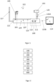
- a testing device 102 has a base plate 129.
- a linear guide 107 is arranged on the base plate 129 as a guide device.
- a holding device 105 which is movable along a guide path of the linear guide 107, is arranged on the linear guide 107.
- the holding device 105 is configured to hold a preform 101 by means of a clamp.
- the guide path comprises at least a first position 121 with a first rotation of the preform 101 of 60° around its own axis and a second position 123 with a second rotation of the preform 101 of 120° around its own axis. axis.
- a camera 103 is rotatably mounted on a tripod 125 on the base plate 129.
- the detection range of the camera 103 comprises at least a first recording position of the preform 101 held by means of the holding device 105 at the first position 121 and a second recording position of the preform 101 held by means of the holding device 105 at the second position 123. Furthermore, a screen 117 is arranged on the base plate 129 opposite the camera 103.
- the preform 101 is arranged between the screen 117 and the camera 103 during sensor data acquisition.
- the detection range of the camera 103 also includes at least a partial area of the screen 117. The screen 117 thus limits the depth of the detection range of the camera 103.
- the testing device 102 has a computer 109 with a data input 111 and a data output 113.
- the camera 103 is connected to the data input 111 via a first data cable 115A.
- the camera 103 sends image data acquired using the first data cable 115A to the computer 109 via the data input 111.
- a display screen 119 is connected to the data output 113 of the computer 109 via a second data cable 115B.
- the preform 101 is guided to the first position 121 at a first time through the interaction of the holding device 105 and the linear guide 107, and the camera 103 records first sensor data at a second time, which shows the preform 101 in a first orientation.
- the camera 103 sends the first sensor data to the computer 109 via the data input 111.
- the preform 101 is guided to the second position 123 at a third time by the holding device 105 in cooperation with the linear guide 107, and the camera 103 records second sensor data of the preform 101 located at the second position 123 at a fourth time.
- the camera 103 sends the second sensor data to the computer 109 via the data input 111 in response to the recording.
- the computer 109 uses an image analysis program to determine compliance with the first test criterion "length” and the second test criterion "condition of the sidewall of the preform 101.” Subsequently, at a sixth time, the computer 109 transmits a signal to the display screen 119 via the data output 113 and using the second data cable 115B. The signal represents the determined compliance with the first test criterion "length” and the second test criterion "condition of the sidewall of the preform 101.” In response to receiving the signal, the display screen 119 displays a stored icon at a seventh time, representing the release of the preform 101.
- the preform In a method for testing a preform placed in a holder of a testing device in a stretch blow molding machine, the preform is positioned 100 at a first position in a 0-degree orientation, then first sensor data of the preform are determined 200 using a CCD camera, and the first sensor data are transmitted to a computer. The preform is then positioned 300 at a second position in a 180-degree orientation, and second sensor data of the preform are determined 400 using the CCD camera, and the second sensor data are transmitted to the computer.
- the computer automatically determines 500 that the first Sensor data fulfill a third test criterion, "diameter,” and the second sensor data fulfill a fourth test criterion, "gray value.”
- the computer outputs an enable signal to a control unit of the test device 600, wherein the enable signal represents the determined fulfillment of the third test criterion, "length,” and the fourth test criterion, "gray value.”
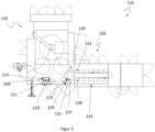
- the testing device 102 is designed as a component of the heating device 133.
- the heating device 133 has an inlet region 137 and, upstream, a heating region 143 and an outlet region 145.
- the heating region 143 has a first heating element 139 at the beginning of the heating region 143. Following the first heating element 139, the heating region 143 has six further heating elements upstream and, after a reversal of the direction of transport, an eighth to thirteenth heating element and, finally, a last heating element 141.
- a preform 101 is placed in a holding device 105 at the beginning of the inlet area 137, and the holding device 105 is then transported through the heating area 143 to the outlet area 145 by means of a chain drive.
- the stretch blow molding system 131 has a CCD camera 103, which records sensor data from the preform 101 located in the inlet area and sends it to the computer 109 for evaluation, which sends a signal to a display screen 119 representing the evaluation result.
- the now heated preform 101 is transferred to the stretch blow molding machine 135, which forms the heated preform 101 into a container.
- the stretch blow molding machine 135 can include the heating area 143.
- the preform 101 to be tested is located in Figure 4 at a fourth position 149 outside a direct detection range of the camera 103, since a Machine component 151 obscures a direct view.
- a mirror 147 is arranged on the base plate 129 by means of a holder 153 such that an image of the preform 101 is visible to the camera 103 via the seal 147.
Landscapes
- Physics & Mathematics (AREA)
- Health & Medical Sciences (AREA)
- Life Sciences & Earth Sciences (AREA)
- Chemical & Material Sciences (AREA)
- Analytical Chemistry (AREA)
- Biochemistry (AREA)
- General Health & Medical Sciences (AREA)
- General Physics & Mathematics (AREA)
- Immunology (AREA)
- Pathology (AREA)
- Engineering & Computer Science (AREA)
- Manufacturing & Machinery (AREA)
- Mechanical Engineering (AREA)
- Blow-Moulding Or Thermoforming Of Plastics Or The Like (AREA)
Applications Claiming Priority (1)
| Application Number | Priority Date | Filing Date | Title |
|---|---|---|---|
| DE102023133494.8A DE102023133494A1 (de) | 2023-11-30 | 2023-11-30 | Prüfeinrichtung zum Prüfen zumindest eines Preforms, Streckblasmaschine und Verfahren zum Prüfen eines Preforms |
Publications (2)
| Publication Number | Publication Date |
|---|---|
| EP4563325A1 true EP4563325A1 (fr) | 2025-06-04 |
| EP4563325B1 EP4563325B1 (fr) | 2026-03-25 |
Family
ID=93335436
Family Applications (1)
| Application Number | Title | Priority Date | Filing Date |
|---|---|---|---|
| EP24209837.4A Active EP4563325B1 (fr) | 2023-11-30 | 2024-10-30 | Dispositif de contrôle pour contrôler au moins une préforme, machine d'étirage-soufflage et procédé de contrôle d'une préforme |
Country Status (2)
| Country | Link |
|---|---|
| EP (1) | EP4563325B1 (fr) |
| DE (1) | DE102023133494A1 (fr) |
Citations (4)
| Publication number | Priority date | Publication date | Assignee | Title |
|---|---|---|---|---|
| EP2112502B1 (fr) * | 2008-04-23 | 2013-02-27 | Finatec Holding AG | Procédé et dispositif de vérification de préformes de récipient |
| EP3181328A1 (fr) * | 2015-12-16 | 2017-06-21 | Sidel Participations | Indexation angulaire d'une preforme chauffee non uniformement par mesure de temperature |
| WO2020177982A1 (fr) | 2019-03-06 | 2020-09-10 | Krones Ag | Procédé de guidage de produit dans une installation de moulage par soufflage-étirage et/ou de mise en bouteilles et installation de moulage par soufflage-étirage et/ou de mise en bouteilles pour bouteilles |
| US20230120081A1 (en) * | 2020-04-09 | 2023-04-20 | Sacmi Cooperativa Meccanici Imola Societa' Cooperativa | Device and Method for Inspecting Parisons |
Family Cites Families (4)
| Publication number | Priority date | Publication date | Assignee | Title |
|---|---|---|---|---|
| DE19542630C2 (de) * | 1995-11-15 | 2001-10-11 | Thomas Huhn | Vorrichtung und Verfahren zum Prüfen von Gefäßwänden |
| DE10259589B3 (de) * | 2002-12-19 | 2004-04-01 | Krones Ag | Verfahren und Vorrichtung zum Herstellen von Hohlkörpern aus Kunststoff |
| DE102012101915A1 (de) * | 2012-03-07 | 2013-09-12 | Krones Ag | Heizvorrichtung und Verfahren zum Temperieren von Vorformlingen |
| US11633763B2 (en) * | 2019-12-16 | 2023-04-25 | Applied Vision Corporation | Sequential imaging for container sidewall inspection |
-
2023
- 2023-11-30 DE DE102023133494.8A patent/DE102023133494A1/de active Pending
-
2024
- 2024-10-30 EP EP24209837.4A patent/EP4563325B1/fr active Active
Patent Citations (4)
| Publication number | Priority date | Publication date | Assignee | Title |
|---|---|---|---|---|
| EP2112502B1 (fr) * | 2008-04-23 | 2013-02-27 | Finatec Holding AG | Procédé et dispositif de vérification de préformes de récipient |
| EP3181328A1 (fr) * | 2015-12-16 | 2017-06-21 | Sidel Participations | Indexation angulaire d'une preforme chauffee non uniformement par mesure de temperature |
| WO2020177982A1 (fr) | 2019-03-06 | 2020-09-10 | Krones Ag | Procédé de guidage de produit dans une installation de moulage par soufflage-étirage et/ou de mise en bouteilles et installation de moulage par soufflage-étirage et/ou de mise en bouteilles pour bouteilles |
| US20230120081A1 (en) * | 2020-04-09 | 2023-04-20 | Sacmi Cooperativa Meccanici Imola Societa' Cooperativa | Device and Method for Inspecting Parisons |
Also Published As
| Publication number | Publication date |
|---|---|
| DE102023133494A1 (de) | 2025-06-05 |
| EP4563325B1 (fr) | 2026-03-25 |
Similar Documents
| Publication | Publication Date | Title |
|---|---|---|
| EP2598861B1 (fr) | Dispositif d'inspection, installation de fabrication équipée d'un dispositif d'inspection et procédé d'inspection de récipients | |
| EP3311146B1 (fr) | Procédé et dispositif d'inspection pour contrôler la fermeture de récipients | |
| DE60315138T3 (de) | Vorrichtung und Verfahren zur Qualitätsüberprüfung von Vorformlingen aus Kunststoff | |
| DE60028756T2 (de) | Methode und vorrichtung zur handhabung von ausgeworfenen sprtizgussteilen | |
| EP2112502B1 (fr) | Procédé et dispositif de vérification de préformes de récipient | |
| EP2759829A1 (fr) | Installation de fabrication pour la fabrication de récipients à partir d'ébauches de récipients et procédé de fabrication | |
| WO2015169727A1 (fr) | Procédé de contrôle d'un rivet | |
| WO2009036715A2 (fr) | Procédé et dispositif de moulage par soufflage de récipients | |
| EP3678845B1 (fr) | Procédé et dispositif pour la vérification de moulage des préformes en matière plastique à conteneurs en matière plastique | |
| DE102021108790A1 (de) | Verfahren zum Auswerten defekter Behältnisse und Defektauswerteeinrichtung für eine Behältnisbehandlungsanlage | |
| EP4232777B1 (fr) | Procédé de fabrication d'un filetage à au moins une extrémité d'au moins un tube métallique et installation de filetage | |
| EP3710777B1 (fr) | Dispositif pour la mesure optique du profil de filetage extérieur de tubes | |
| DE102016205137A1 (de) | Verfahren und Biegemaschine zur Herstellung eines mehrdimensional gebogenen Biegeteils | |
| EP3630448B1 (fr) | Dispositif et procede de traitement de recipients avec un dispositif d'inspection optique | |
| EP2489469B1 (fr) | Cartouche de pièce de blocage | |
| DE102019132655A1 (de) | Verfahren zum Überprüfen einer Wandstärke eines Behälters aus einem zumindest teilweise transparenten Material | |
| DE19914028C1 (de) | Verfahren und Vorrichtung zur Inspektion von Hohlkörpern aus Kunststoff | |
| EP4563325B1 (fr) | Dispositif de contrôle pour contrôler au moins une préforme, machine d'étirage-soufflage et procédé de contrôle d'une préforme | |
| DE19746150A1 (de) | Vorrichtung zur Prüfung von Vorformlingen | |
| WO2018197297A1 (fr) | Procédé et dispositif d'inspection destinés à inspecter des récipients par traitement d'images | |
| DE102005011330B4 (de) | Verfahren zur Lageerkennung eines Formteils | |
| EP2567220A1 (fr) | Procédé et dispositif de contrôle d'objets pour applications pharmaceutiques | |
| EP4449211A1 (fr) | Appareil d'usinage de pièces et procédé de commande d'une machine-outil | |
| EP4498072A1 (fr) | Procédé et dispositif d'inspection d'au moins une surface extérieure de récipients | |
| EP4434718A2 (fr) | Dispositif et procédé de chauffage d'ébauches en plastique avec inspection des dispositifs de retenue |
Legal Events
| Date | Code | Title | Description |
|---|---|---|---|
| PUAI | Public reference made under article 153(3) epc to a published international application that has entered the european phase |
Free format text: ORIGINAL CODE: 0009012 |
|
| STAA | Information on the status of an ep patent application or granted ep patent |
Free format text: STATUS: THE APPLICATION HAS BEEN PUBLISHED |
|
| AK | Designated contracting states |
Kind code of ref document: A1 Designated state(s): AL AT BE BG CH CY CZ DE DK EE ES FI FR GB GR HR HU IE IS IT LI LT LU LV MC ME MK MT NL NO PL PT RO RS SE SI SK SM TR |
|
| STAA | Information on the status of an ep patent application or granted ep patent |
Free format text: STATUS: REQUEST FOR EXAMINATION WAS MADE |
|
| 17P | Request for examination filed |
Effective date: 20250613 |
|
| GRAP | Despatch of communication of intention to grant a patent |
Free format text: ORIGINAL CODE: EPIDOSNIGR1 |
|
| STAA | Information on the status of an ep patent application or granted ep patent |
Free format text: STATUS: GRANT OF PATENT IS INTENDED |
|
| RIC1 | Information provided on ipc code assigned before grant |
Ipc: B29C 49/78 20060101AFI20251104BHEP Ipc: G01N 21/90 20060101ALI20251104BHEP Ipc: B29C 49/06 20060101ALN20251104BHEP Ipc: B29C 49/64 20060101ALN20251104BHEP Ipc: B29K 67/00 20060101ALN20251104BHEP Ipc: B29L 31/00 20060101ALN20251104BHEP |
|
| INTG | Intention to grant announced |
Effective date: 20251119 |
|
| P01 | Opt-out of the competence of the unified patent court (upc) registered |
Free format text: CASE NUMBER: UPC_APP_0014560_4563325/2025 Effective date: 20251125 |
|
| GRAS | Grant fee paid |
Free format text: ORIGINAL CODE: EPIDOSNIGR3 |
|
| GRAA | (expected) grant |
Free format text: ORIGINAL CODE: 0009210 |
|
| STAA | Information on the status of an ep patent application or granted ep patent |
Free format text: STATUS: THE PATENT HAS BEEN GRANTED |
|
| AK | Designated contracting states |
Kind code of ref document: B1 Designated state(s): AL AT BE BG CH CY CZ DE DK EE ES FI FR GB GR HR HU IE IS IT LI LT LU LV MC ME MK MT NL NO PL PT RO RS SE SI SK SM TR |
|
| REG | Reference to a national code |
Ref country code: CH Ref legal event code: F10 Free format text: ST27 STATUS EVENT CODE: U-0-0-F10-F00 (AS PROVIDED BY THE NATIONAL OFFICE) Effective date: 20260325 Ref country code: GB Ref legal event code: FG4D Free format text: NOT ENGLISH |
|
| REG | Reference to a national code |
Ref country code: DE Ref legal event code: R096 Ref document number: 502024000935 Country of ref document: DE |
|
| REG | Reference to a national code |
Ref country code: IE Ref legal event code: FG4D Free format text: LANGUAGE OF EP DOCUMENT: GERMAN |