EP4563997A2 - Procédé de mesure de l'absorbance d'une substance dans une solution et dispositif de mesure associé - Google Patents
Procédé de mesure de l'absorbance d'une substance dans une solution et dispositif de mesure associé Download PDFInfo
- Publication number
- EP4563997A2 EP4563997A2 EP25162158.7A EP25162158A EP4563997A2 EP 4563997 A2 EP4563997 A2 EP 4563997A2 EP 25162158 A EP25162158 A EP 25162158A EP 4563997 A2 EP4563997 A2 EP 4563997A2
- Authority
- EP
- European Patent Office
- Prior art keywords
- light ray
- signal
- reference light
- measuring
- detector
- Prior art date
- Legal status (The legal status is an assumption and is not a legal conclusion. Google has not performed a legal analysis and makes no representation as to the accuracy of the status listed.)
- Pending
Links
Images


Classifications
-
- G—PHYSICS
- G01—MEASURING; TESTING
- G01N—INVESTIGATING OR ANALYSING MATERIALS BY DETERMINING THEIR CHEMICAL OR PHYSICAL PROPERTIES
- G01N21/00—Investigating or analysing materials by the use of optical means, i.e. using sub-millimetre waves, infrared, visible or ultraviolet light
- G01N21/17—Systems in which incident light is modified in accordance with the properties of the material investigated
- G01N21/25—Colour; Spectral properties, i.e. comparison of effect of material on the light at two or more different wavelengths or wavelength bands
- G01N21/31—Investigating relative effect of material at wavelengths characteristic of specific elements or molecules, e.g. atomic absorption spectrometry
- G01N21/33—Investigating relative effect of material at wavelengths characteristic of specific elements or molecules, e.g. atomic absorption spectrometry using ultraviolet light
-
- G—PHYSICS
- G01—MEASURING; TESTING
- G01N—INVESTIGATING OR ANALYSING MATERIALS BY DETERMINING THEIR CHEMICAL OR PHYSICAL PROPERTIES
- G01N21/00—Investigating or analysing materials by the use of optical means, i.e. using sub-millimetre waves, infrared, visible or ultraviolet light
- G01N21/01—Arrangements or apparatus for facilitating the optical investigation
- G01N21/03—Cuvette constructions
- G01N21/05—Flow-through cuvettes
-
- G—PHYSICS
- G01—MEASURING; TESTING
- G01N—INVESTIGATING OR ANALYSING MATERIALS BY DETERMINING THEIR CHEMICAL OR PHYSICAL PROPERTIES
- G01N21/00—Investigating or analysing materials by the use of optical means, i.e. using sub-millimetre waves, infrared, visible or ultraviolet light
- G01N21/84—Systems specially adapted for particular applications
- G01N21/85—Investigating moving fluids or granular solids
- G01N21/8507—Probe photometers, i.e. with optical measuring part dipped into fluid sample
-
- G—PHYSICS
- G01—MEASURING; TESTING
- G01N—INVESTIGATING OR ANALYSING MATERIALS BY DETERMINING THEIR CHEMICAL OR PHYSICAL PROPERTIES
- G01N30/00—Investigating or analysing materials by separation into components using adsorption, absorption or similar phenomena or using ion-exchange, e.g. chromatography or field flow fractionation
- G01N30/02—Column chromatography
-
- G—PHYSICS
- G01—MEASURING; TESTING
- G01N—INVESTIGATING OR ANALYSING MATERIALS BY DETERMINING THEIR CHEMICAL OR PHYSICAL PROPERTIES
- G01N30/00—Investigating or analysing materials by separation into components using adsorption, absorption or similar phenomena or using ion-exchange, e.g. chromatography or field flow fractionation
- G01N30/02—Column chromatography
- G01N30/62—Detectors specially adapted therefor
- G01N30/74—Optical detectors
-
- G—PHYSICS
- G01—MEASURING; TESTING
- G01N—INVESTIGATING OR ANALYSING MATERIALS BY DETERMINING THEIR CHEMICAL OR PHYSICAL PROPERTIES
- G01N21/00—Investigating or analysing materials by the use of optical means, i.e. using sub-millimetre waves, infrared, visible or ultraviolet light
- G01N21/17—Systems in which incident light is modified in accordance with the properties of the material investigated
- G01N21/25—Colour; Spectral properties, i.e. comparison of effect of material on the light at two or more different wavelengths or wavelength bands
- G01N21/31—Investigating relative effect of material at wavelengths characteristic of specific elements or molecules, e.g. atomic absorption spectrometry
- G01N2021/3125—Measuring the absorption by excited molecules
-
- G—PHYSICS
- G01—MEASURING; TESTING
- G01N—INVESTIGATING OR ANALYSING MATERIALS BY DETERMINING THEIR CHEMICAL OR PHYSICAL PROPERTIES
- G01N30/00—Investigating or analysing materials by separation into components using adsorption, absorption or similar phenomena or using ion-exchange, e.g. chromatography or field flow fractionation
- G01N30/02—Column chromatography
- G01N2030/022—Column chromatography characterised by the kind of separation mechanism
- G01N2030/027—Liquid chromatography
-
- G—PHYSICS
- G01—MEASURING; TESTING
- G01N—INVESTIGATING OR ANALYSING MATERIALS BY DETERMINING THEIR CHEMICAL OR PHYSICAL PROPERTIES
- G01N2201/00—Features of devices classified in G01N21/00
- G01N2201/06—Illumination; Optics
- G01N2201/062—LED's
- G01N2201/0624—Compensating variation in output of LED source
-
- G—PHYSICS
- G01—MEASURING; TESTING
- G01N—INVESTIGATING OR ANALYSING MATERIALS BY DETERMINING THEIR CHEMICAL OR PHYSICAL PROPERTIES
- G01N2201/00—Features of devices classified in G01N21/00
- G01N2201/06—Illumination; Optics
- G01N2201/062—LED's
- G01N2201/0625—Modulated LED
-
- G—PHYSICS
- G01—MEASURING; TESTING
- G01N—INVESTIGATING OR ANALYSING MATERIALS BY DETERMINING THEIR CHEMICAL OR PHYSICAL PROPERTIES
- G01N2201/00—Features of devices classified in G01N21/00
- G01N2201/06—Illumination; Optics
- G01N2201/069—Supply of sources
- G01N2201/0691—Modulated (not pulsed supply)
-
- G—PHYSICS
- G01—MEASURING; TESTING
- G01N—INVESTIGATING OR ANALYSING MATERIALS BY DETERMINING THEIR CHEMICAL OR PHYSICAL PROPERTIES
- G01N2201/00—Features of devices classified in G01N21/00
- G01N2201/12—Circuits of general importance; Signal processing
- G01N2201/127—Calibration; base line adjustment; drift compensation
Definitions
- the present invention relates to a method and a measuring device for measuring the absorbance of a substance in a solution.
- the UV region can be considered to consist of light of wavelength in the region of 10 nm to 400 nm, light of wavelength of 180 nm to 300 nm being known as 'deep UV'.
- Most analytical instruments for detecting substances which absorb in the deep ultra violet (UV) region use a mercury- lamp, deuterium lamp or xenon flash lamp as a light source.
- a mercury- lamp e.g. a mercury-lamp
- a UV detector e.g. a photomultiplier, a photodiode or a photo transistor
- Proteins have mainly two absorption peaks in the deep UV region, one very strong absorption band with a maximum at about 190 nm, where peptide bonds absorb, and another less intense peak at about 280 nm due to light absorption by aromatic amino acids (e.g. tyrosine, tryptophan and phenylalanine).
- aromatic amino acids e.g. tyrosine, tryptophan and phenylalanine
- WO2007/062800 and WO2013/178770 describe the use of a UV LED as a source of light for analysis of the concentration of a substance in a liquid sample.
- the incoming light to the measuring arrangement from the UV LED is divided into a reference light ray provided directly to a detector and a signal light ray provided through the sample and then to a detector.
- the detected signal light ray is greatly amplified and compared to an amplified version of the detected reference light ray.
- An object of the present invention is to provide an improved method and a measuring device for measuring the absorbance of light of a substance in a solution in a measuring cell.
- a further object of the present invention is to provide a method and a measuring device for measuring the absorbance of light of a substance in a solution in a measuring cell which are robust and reliable.
- a method for measuring the absorbance of light of a substance in a solution in a measuring cell comprising the steps of:
- a measuring device for measuring the absorbance of a substance in a solution in a measuring cell of the measuring device, wherein said measuring device comprises:
- the signal light ray and the reference light ray can be detected in the same detector simultaneously.
- the step of modulating the signal light ray comprises modulating the signal light ray at a first frequency and the step of modulating the reference light ray comprises modulating the reference light ray at a second frequency which is different from the first frequency.
- the two signals can be differentiated in the detector.
- the steps of modulating the signal light ray and the reference light ray comprise creating a sine modulation or a square wave modulation to both the signal light ray and the reference light ray.
- the measuring cell is a flow cell.
- the method further comprises the step of changing direction of one or both of the signal light ray and the reference light ray with at least one light direction changing device such that both the signal light ray and the reference light ray can be detected by the same detector.
- the step of modulating one of the signal light ray or the reference light ray comprises controlling the light source.
- the measuring device further comprises at least one light direction changing device arranged to change the direction of the reference light ray or the signal light ray such that they can be detected by the same detector.
- the first signal modulation device and the second signal modulation device are arranged to modulate the signals at different frequencies.
- the first signal modulation device is a chopper, a shutter, a movable mirror, a tuning fork or an adjustable gray filter provided somewhere in the light path of the signal light ray.
- the second signal modulation device is a chopper, a shutter, a movable mirror, a tuning fork or an adjustable gray filter provided somewhere in the light path of the reference light ray.
- one of the first or second signal modulation device is a device controlling the light source.
- the beam splitter is an asymmetrical beam splitter dividing the first light beam into a signal light ray and a reference light ray where a larger portion of the first light beam is directed to the signal light ray than to the reference light ray.
- Figure 1 shows schematically a measuring device 1 of prior art for measuring the absorbance of a substance in a solution provided in a measuring cell 3.
- the measuring device 1 comprises a light source 5 which is transmitting a first light ray 7.
- the measuring device comprises a beam splitter 9 provided in the measuring device such that the first light ray 7 is divided by the beam splitter 9 into a signal light ray 11 and a reference light ray 13.
- the measuring device 1 comprises further the measuring cell 3 which is positioned such that the signal light ray 11 will pass through the solution in the measuring cell 3.
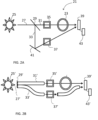
- FIG. 2a shows schematically a measuring device 21 according to one embodiment of the invention.
- the measuring device 21 is arranged for measuring the absorbance of a substance in a solution provided in a measuring cell 23 of the measuring device.
- the measuring device 21 comprises a light source 25 which is transmitting a first light beam 27.
- the light source could be for example a LED or any other type of suitable lamp.
- the measuring device comprises further a beam splitter 29 provided such that the first light beam 27 is divided by the beam splitter 29 into a signal light ray 31 and a reference light ray 33.
- the beam splitter 29 can be for example a semitransparent mirror or two optical fibers side by side.
- the measuring device 21 comprises further the measuring cell 23 positioned such that the signal light ray 31 will pass through the solution in the measuring cell 23.
- the measuring cell 23 can be a static measuring cell comprising a sample to be measured but it could also be a flow cell in which the sample is flowing through during continuous measurements.
- the measuring device 21 furthermore comprises a first signal modulation device 35 arranged to modulate the signal light ray 31 and a second signal modulation device 37 arranged to modulate the reference light ray 33.
- the first signal modulation device 35 is in this embodiment positioned between the beam splitter 29 and the measuring cell 23. However it could also be positioned after the measuring cell 23 but before a detector 39 also provided in the measuring device 21.
- the detector 39 is according to the invention arranged to detect the signal light ray 31 when it has been modulated and passed the measuring cell 23 and also detect the reference light ray 33 when it has been modulated. In this shown embodiment the detector 39 is provided such that the signal light ray 31 is detected by the detector 39 without any further redirection.
- the reference light ray 33 is instead in this embodiment redirected by a light direction changing device 41 such that the reference light ray 33 after redirection by the light direction changing device 41 and modulation by the second signal modulation device 37 is detected by the detector 39.
- the light direction changing device could be a mirror.
- the second signal modulation device 37 is here shown to be provided after the light direction changing device 41 but it could also be provided between the beam splitter 29 and the light direction changing device 41.
- the light direction changing device 41 could instead be provided in the signal light ray path and the detector 39 in the path way of the reference light ray, i.e. the direction of the reference light ray 33 directly after the beam splitter 29.
- More than one light direction changing device could also be provided in the measuring device in order to direct the signal light ray and the reference light ray to the same detector in a suitable way.
- Another alternative which would not require a light direction changing device at all could be to let two slightly divergent light rays from the light source fall onto a detector which is big enough for receiving them both or by guiding the light in optical fibers.
- the alternative with optical fibers is shown in Figure 2b . See further description below.
- both the signal light ray 31 and the reference light ray 33 are detected by the same detector 39.
- the detector 39 comprises or is connected to a processing device 43 which is configured for performing synchronous detection of the detected signal in order to reconstruct the intensities of the signal light ray 31 and the reference light ray 33 from the combined signal detected by the detector 39. This is achieved by multiplying the detector signal by the modulation signals respectively and then low-pass filtering the results. In this way the two different signals are reconstructed and from them the absorption can be calculated.
- the processing device 43 can be completely made of hardware, completely made in software or a combination of the two. With this measuring device the signal light ray 31 and the reference light ray 33 can be detected simultaneously by the same detector 39.
- the detector 39 comprises also normally a photo diode, an amplifier and an AD converter (not shown in the Figure). Furthermore an optical arrangement is usually provided between the light source 25 and the beam splitter 29. However this is not shown in the figures. This optical arrangement can comprise a collimating lens, an aperture and possibly also a filter.
- the first signal modulation device 35 and the second signal modulation device 37 can for example be a chopper, a shutter, a movable mirror, a tuning fork or an adjustable grey filter. They could be separate devices or provided in the same device if the design of the measuring device and distances between the signal light ray and the reference light ray allows that.
- the first signal modulation device 35 and the second signal modulation device 37 should modulate the signals at different frequencies such that they can be differentiated in the detector.
- the modulation of the light rays creates an amplitude modulation at a set frequency.
- the reference light ray can be modulated at a frequency somewhere in the range from 100 Hz to a few kHz and the signal light ray is modulated at a frequency that differs with at least 30% from the first frequency.
- the frequencies need to be chosen such that they do not interfere with other frequencies or their harmonics in the system.
- the amplitude modulation can be sine modulation, square wave modulation or any other waveform that is suitable.
- one of the first or the second signal modulation device 35, 37 is instead a device which is controlling the light source 25.
- Controlling the light source 25, such as for example turn it on and off by a specific frequency will of course affect both the signal light ray and the reference light ray but in combination with one signal modulation device in either the signal light ray or the reference light ray the two signals can still be differentiated from each other in the detector in a correct way if the measured signal is adjusted by adding the difference between the "light on"/"modulator on” and the "light on"/"modulator off” value to each "light off"/"modulator on” portion of the signal.
- the beam splitter 29 can be an asymmetrical beam splitter where a larger portion of the first light beam 27 is directed into the signal light ray 31 than the reference light ray 33. This could be useful since a larger part of the dynamic range of the detector then is used for the signal light ray.
- Figure 2b shows schematically a measuring device 21' according to another embodiment of the invention.
- the beam splitter 29' is provided as two optical fibers.
- the first light beam 27' light from the light source 25', is divided into a signal light ray 31' which is transferred in a first optical fiber and a reference light ray 33' which is transferred in a second optical fiber.
- the signal light ray 31' is modulated in a first signal modulation device 35'.
- the signal light ray 31' will pass through the solution in the measuring cell 23' before it is detected in the detector 39'.
- the reference light ray 33' is modulated in a second signal modulation device 37' before it is detected in the same detector 39'.
- Most of the details of this embodiment are the same as in the embodiment described above and will not be described further here.
- Figure 3 is a flow chart of a method for measuring the absorbance of light of a substance in a solution in a measuring cell 23 according to one embodiment of the invention. The method comprises the steps as described below, also with reference to Figure 2 :
- the step of modulating the signal light ray comprises modulating the signal light ray at a first frequency and the step of modulating the reference light ray comprises modulating the reference light ray at a second frequency which is different from the first frequency.
- the amplitude modulation waveform could be a sine, square wave or any suitable waveform.
- S11 Detecting a signal in a detector 39, which signal is the combined signal intensity of the signal light ray 31 and the reference light ray 33 detected by the detector 39.
- S15 Performing synchronous detection of the detected signal in order to reconstruct the intensities of the signal light ray 31 and the reference light ray 33 from the combined signal detected by the detector 39 based on the modulation performed to the signal light ray 31 and the reference light ray 33.
- the detecting of the signal light ray 31 in the detector 39 and the detecting of the reference light ray 33 in the same detector 39 can with this method be performed simultaneously.
- the method further comprises the step of changing direction of one or both of the signal light ray 31 and the reference light ray 33 with at least one light direction changing device 41 such that both the signal light ray and the reference light ray can be detected by the same detector 39.
- Another alternative could be to use optical fibers as discussed above.
- the measuring cell In applications where a sample is flowing through the measuring cell the measuring cell is called a flow cell.
- a protein concentration can be measured in an outflow from a chromatography column.
- the outflow from the chromatography column is provided through a flow cell of a measuring device according to the invention.
- the long and continuous measurements of flowing samples are much more sensitive to drift in the system compared to when measuring on a static sample.
- the method and measuring device according to this invention is especially suitable for measuring the absorbance of a substance in a solution provided in a flow cell.
Landscapes
- Physics & Mathematics (AREA)
- Biochemistry (AREA)
- Health & Medical Sciences (AREA)
- Life Sciences & Earth Sciences (AREA)
- Chemical & Material Sciences (AREA)
- Analytical Chemistry (AREA)
- General Health & Medical Sciences (AREA)
- General Physics & Mathematics (AREA)
- Immunology (AREA)
- Pathology (AREA)
- Spectroscopy & Molecular Physics (AREA)
- Investigating Or Analysing Materials By Optical Means (AREA)
- Spectrometry And Color Measurement (AREA)
Applications Claiming Priority (3)
| Application Number | Priority Date | Filing Date | Title |
|---|---|---|---|
| GBGB1612010.7A GB201612010D0 (en) | 2016-07-11 | 2016-07-11 | A method and a measuring device for measuring the absorbance of a substance in a solution |
| EP17735452.9A EP3482190B1 (fr) | 2016-07-11 | 2017-06-27 | Procédé de mesure de l'absorbange d'une substance dans une solution et un dispositif de mesure correspondant |
| PCT/EP2017/065912 WO2018010956A1 (fr) | 2016-07-11 | 2017-06-27 | Procédé de mesure de l'absorbance d'une substance dans une solution, et dispositif de mesure associé |
Related Parent Applications (2)
| Application Number | Title | Priority Date | Filing Date |
|---|---|---|---|
| EP17735452.9A Division EP3482190B1 (fr) | 2016-07-11 | 2017-06-27 | Procédé de mesure de l'absorbange d'une substance dans une solution et un dispositif de mesure correspondant |
| EP17735452.9A Division-Into EP3482190B1 (fr) | 2016-07-11 | 2017-06-27 | Procédé de mesure de l'absorbange d'une substance dans une solution et un dispositif de mesure correspondant |
Publications (2)
| Publication Number | Publication Date |
|---|---|
| EP4563997A2 true EP4563997A2 (fr) | 2025-06-04 |
| EP4563997A3 EP4563997A3 (fr) | 2025-08-06 |
Family
ID=56890840
Family Applications (2)
| Application Number | Title | Priority Date | Filing Date |
|---|---|---|---|
| EP25162158.7A Pending EP4563997A3 (fr) | 2016-07-11 | 2017-06-27 | Procédé de mesure de l'absorbance d'une substance dans une solution et dispositif de mesure associé |
| EP17735452.9A Active EP3482190B1 (fr) | 2016-07-11 | 2017-06-27 | Procédé de mesure de l'absorbange d'une substance dans une solution et un dispositif de mesure correspondant |
Family Applications After (1)
| Application Number | Title | Priority Date | Filing Date |
|---|---|---|---|
| EP17735452.9A Active EP3482190B1 (fr) | 2016-07-11 | 2017-06-27 | Procédé de mesure de l'absorbange d'une substance dans une solution et un dispositif de mesure correspondant |
Country Status (6)
| Country | Link |
|---|---|
| US (2) | US11815451B2 (fr) |
| EP (2) | EP4563997A3 (fr) |
| JP (1) | JP7308744B2 (fr) |
| CN (2) | CN109477792A (fr) |
| GB (1) | GB201612010D0 (fr) |
| WO (1) | WO2018010956A1 (fr) |
Families Citing this family (4)
| Publication number | Priority date | Publication date | Assignee | Title |
|---|---|---|---|---|
| CN112902835A (zh) * | 2019-12-04 | 2021-06-04 | 阳程科技股份有限公司 | 光学对位检测装置及其检测方法 |
| DE102020209268B3 (de) * | 2020-07-22 | 2021-10-14 | Hochschule Emden/Leer | Optisches System |
| CN116106230B (zh) * | 2022-12-29 | 2026-01-30 | 南京港能环境科技有限公司 | 一种双路环境检测信号处理电路及介质浓度检测系统 |
| CN119757205A (zh) * | 2024-12-24 | 2025-04-04 | 中国科学院西安光学精密机械研究所 | 用于海水硝酸盐浓度测量的紧凑型紫外双路光学系统 |
Citations (2)
| Publication number | Priority date | Publication date | Assignee | Title |
|---|---|---|---|---|
| WO2007062800A1 (fr) | 2005-11-29 | 2007-06-07 | Ge Healthcare Bio-Sciences Ab | Procedes et appareil de mesure de la concentration d’une substance dans une solution |
| WO2013178770A1 (fr) | 2012-05-31 | 2013-12-05 | Ge Healthcare Bio-Sciences Ab | Procédés et appareil de mesure de l'absorption de la lumière d'une substance dans une solution |
Family Cites Families (27)
| Publication number | Priority date | Publication date | Assignee | Title |
|---|---|---|---|---|
| US3834821A (en) * | 1971-01-12 | 1974-09-10 | Damon Corp | Multiple photometer assembly |
| US4008394A (en) | 1973-06-28 | 1977-02-15 | Sensors, Inc. | Gas analyzing |
| JPS5348055B2 (fr) | 1973-12-07 | 1978-12-26 | ||
| JPS51136472A (en) * | 1975-05-20 | 1976-11-25 | Sanyo Electric Co Ltd | Absorbing type gas density measuring |
| JPS56150332A (en) * | 1980-04-24 | 1981-11-20 | Fujitsu Ltd | Infrared spectroscopic analysis method |
| SU1114150A1 (ru) | 1982-10-25 | 1991-06-30 | Институт физики АН БССР | Двухканальный газоанализатор |
| JPS59107221A (ja) * | 1982-12-11 | 1984-06-21 | Japan Spectroscopic Co | 分光光度計 |
| JPS6093945A (ja) * | 1983-10-28 | 1985-05-25 | Shimadzu Corp | 光伝送式計測装置の伝送損失補償方法 |
| SU1356703A1 (ru) | 1985-07-01 | 1991-06-30 | Институт физики АН БССР | Оптический газоанализатор |
| SU1398589A1 (ru) | 1986-03-18 | 1991-06-30 | Институт физики АН БССР | Газоанализатор |
| SU1462986A1 (ru) | 1986-04-07 | 1991-03-23 | Институт физики АН БССР | Газоанализатор |
| EP0458601B1 (fr) * | 1990-05-22 | 1996-08-28 | Research Development Corporation Of Japan | Méthode et appareil pour mesurer l'absorption spectrale dans des échantillons opaques et méthode et appareil pour mesurer une distribution d'absorption microscopique |
| US5504337A (en) * | 1990-10-10 | 1996-04-02 | Joseph R. Lakowicz | Method and apparatus for performing phase fluorescence lifetime measurements in flow cytometry |
| JP2973639B2 (ja) * | 1991-09-30 | 1999-11-08 | 横河電機株式会社 | シ―ト状物体の特性測定装置 |
| JP2000019108A (ja) | 1998-07-06 | 2000-01-21 | Horiba Ltd | 赤外線ガス分析計 |
| JP2005301202A (ja) * | 2004-03-19 | 2005-10-27 | Fuji Xerox Co Ltd | ホログラム記録媒体およびこれを用いたホログラム記録方法 |
| US7468788B2 (en) * | 2005-06-21 | 2008-12-23 | Stheno Corporation | Systems and methods for chiral detection and analysis |
| JP2007093410A (ja) * | 2005-09-29 | 2007-04-12 | Shimadzu Corp | 分光光度計 |
| US7675030B2 (en) * | 2005-11-14 | 2010-03-09 | Schlumberger Technology Corporation | Logging system and method for in-situ fluids sensing through optical fiber with attenuation compensation |
| CN101561391A (zh) * | 2009-06-04 | 2009-10-21 | 中国航空工业集团公司西安飞机设计研究所 | 一种气体浓度测试装置及测试方法 |
| US8899114B2 (en) * | 2009-07-30 | 2014-12-02 | Halliburton Energy Services, Inc. | Energy intensity transformation |
| WO2011093775A1 (fr) * | 2010-01-28 | 2011-08-04 | Ge Healthcare Bio-Sciences Ab | Détecteur optique à cuve de circulation |
| US9494567B2 (en) * | 2012-12-31 | 2016-11-15 | Omni Medsci, Inc. | Near-infrared lasers for non-invasive monitoring of glucose, ketones, HBA1C, and other blood constituents |
| US20140361172A1 (en) * | 2013-06-11 | 2014-12-11 | Jp3 Measurement, Llc | Detection of h2s in natural gas and hydrocarbon streams using a dual-path near-ir spectroscopy system |
| WO2015044020A2 (fr) * | 2013-09-24 | 2015-04-02 | Ge Healthcare Bio-Sciences Ab | Système de moniteur d'absorption optique |
| CN103698295B (zh) * | 2013-12-20 | 2016-03-02 | 中国科学技术大学 | 一种微型远红外气体浓度监测方法及装置 |
| US9772287B2 (en) * | 2014-04-16 | 2017-09-26 | Saudi Arabian Oil Company | Sensor for monitoring for the presence and measurement of aqueous aldehyde biocides |
-
2016
- 2016-07-11 GB GBGB1612010.7A patent/GB201612010D0/en not_active Ceased
-
2017
- 2017-06-27 US US16/316,276 patent/US11815451B2/en active Active
- 2017-06-27 WO PCT/EP2017/065912 patent/WO2018010956A1/fr not_active Ceased
- 2017-06-27 EP EP25162158.7A patent/EP4563997A3/fr active Pending
- 2017-06-27 CN CN201780043398.9A patent/CN109477792A/zh active Pending
- 2017-06-27 CN CN202510602453.XA patent/CN120385639A/zh active Pending
- 2017-06-27 JP JP2019500830A patent/JP7308744B2/ja active Active
- 2017-06-27 EP EP17735452.9A patent/EP3482190B1/fr active Active
-
2023
- 2023-10-04 US US18/481,117 patent/US12276601B2/en active Active
Patent Citations (2)
| Publication number | Priority date | Publication date | Assignee | Title |
|---|---|---|---|---|
| WO2007062800A1 (fr) | 2005-11-29 | 2007-06-07 | Ge Healthcare Bio-Sciences Ab | Procedes et appareil de mesure de la concentration d’une substance dans une solution |
| WO2013178770A1 (fr) | 2012-05-31 | 2013-12-05 | Ge Healthcare Bio-Sciences Ab | Procédés et appareil de mesure de l'absorption de la lumière d'une substance dans une solution |
Also Published As
| Publication number | Publication date |
|---|---|
| US20240027337A1 (en) | 2024-01-25 |
| US12276601B2 (en) | 2025-04-15 |
| JP7308744B2 (ja) | 2023-07-14 |
| EP4563997A3 (fr) | 2025-08-06 |
| WO2018010956A1 (fr) | 2018-01-18 |
| CN109477792A (zh) | 2019-03-15 |
| US20190323953A1 (en) | 2019-10-24 |
| JP2019522202A (ja) | 2019-08-08 |
| EP3482190A1 (fr) | 2019-05-15 |
| US11815451B2 (en) | 2023-11-14 |
| CN120385639A (zh) | 2025-07-29 |
| EP3482190B1 (fr) | 2025-05-14 |
| GB201612010D0 (en) | 2016-08-24 |
Similar Documents
| Publication | Publication Date | Title |
|---|---|---|
| US12276601B2 (en) | Method for measuring the absorbance of a substance in a solution and a measuring device therefor | |
| JP5828440B1 (ja) | 微小粒子測定装置 | |
| US20230101434A1 (en) | Apparatus and Method for Measuring the Light Absorbance of a Substance in a Solution | |
| Kraiczek et al. | Highly flexible UV–vis radiation sources and novel detection schemes for spectrophotometric HPLC detection | |
| US20100141938A1 (en) | Method and apparatus for detection of analytes | |
| JPS6337339B2 (fr) | ||
| US10760968B2 (en) | Spectrometric measuring device | |
| US11499913B2 (en) | Method and device for measuring absorbance of a substance in solution with multiple light rays | |
| JP2004020539A (ja) | 赤外円二色性測定装置および赤外円二色性測定方法 | |
| O'Toole et al. | Paired emitter–detector diode detection with dual wavelength monitoring for enhanced sensitivity to transition metals in ion chromatography with post-column reaction | |
| WO2023109603A1 (fr) | Procédé et système de détermination spectroscopique d'échantillon, et cytomètre en flux | |
| JP2020521129A (ja) | キャピラリー分離技法使用後のオンカラム検出用の統合された蛍光/吸光検出器 | |
| JP3755997B2 (ja) | 液体クロマトグラフ | |
| CN119827687A (zh) | 一种同时测量荧光及紫外可见吸收的两用检测器 | |
| KR20170002840A (ko) | 다파장 측정 광 검출기 | |
| CN107003182B (zh) | 用于测量光吸收或确定物质的浓度的系统的光纤布置 | |
| CN111693460A (zh) | 一种基于偏振光束饱和吸收光谱的检测装置 | |
| KR20220114111A (ko) | 다중포트 광커플러 기반 광간섭계를 이용한 표적물질 농도 측정 장치 | |
| RU1808125C (ru) | Способ анализа газов и устройство дл его осуществлени | |
| JPH02240532A (ja) | 分光光度計 | |
| WO2018003045A1 (fr) | Diviseur de faisceau à fonction d'ouverture, et détecteur muni dudit diviseur de faisceau. | |
| JPH03214040A (ja) | 光分析装置 | |
| SU892229A1 (ru) | Детектор дл жидкостной хроматографии | |
| JP3602980B2 (ja) | 電気泳動分析方法及びその装置 | |
| JPH0572125A (ja) | 示差屈折率分光スペクトル測定装置 |
Legal Events
| Date | Code | Title | Description |
|---|---|---|---|
| PUAI | Public reference made under article 153(3) epc to a published international application that has entered the european phase |
Free format text: ORIGINAL CODE: 0009012 |
|
| STAA | Information on the status of an ep patent application or granted ep patent |
Free format text: STATUS: THE APPLICATION HAS BEEN PUBLISHED |
|
| AC | Divisional application: reference to earlier application |
Ref document number: 3482190 Country of ref document: EP Kind code of ref document: P |
|
| AK | Designated contracting states |
Kind code of ref document: A2 Designated state(s): AL AT BE BG CH CY CZ DE DK EE ES FI FR GB GR HR HU IE IS IT LI LT LU LV MC MK MT NL NO PL PT RO RS SE SI SK SM TR |
|
| REG | Reference to a national code |
Ref country code: DE Ref legal event code: R079 Free format text: PREVIOUS MAIN CLASS: G01N0030020000 Ipc: G01N0021330000 |
|
| PUAL | Search report despatched |
Free format text: ORIGINAL CODE: 0009013 |
|
| AK | Designated contracting states |
Kind code of ref document: A3 Designated state(s): AL AT BE BG CH CY CZ DE DK EE ES FI FR GB GR HR HU IE IS IT LI LT LU LV MC MK MT NL NO PL PT RO RS SE SI SK SM TR |
|
| RIC1 | Information provided on ipc code assigned before grant |
Ipc: G01N 21/33 20060101AFI20250702BHEP Ipc: G01N 21/05 20060101ALN20250702BHEP Ipc: G01N 30/74 20060101ALN20250702BHEP |
|
| STAA | Information on the status of an ep patent application or granted ep patent |
Free format text: STATUS: REQUEST FOR EXAMINATION WAS MADE |
|
| 17P | Request for examination filed |
Effective date: 20260130 |