EP4567486A1 - Dispositif de guidage de faisceau pour guider un rayonnement lumineux de signal - Google Patents
Dispositif de guidage de faisceau pour guider un rayonnement lumineux de signal Download PDFInfo
- Publication number
- EP4567486A1 EP4567486A1 EP24214247.9A EP24214247A EP4567486A1 EP 4567486 A1 EP4567486 A1 EP 4567486A1 EP 24214247 A EP24214247 A EP 24214247A EP 4567486 A1 EP4567486 A1 EP 4567486A1
- Authority
- EP
- European Patent Office
- Prior art keywords
- fiber
- elements
- guiding device
- beam guiding
- signal light
- Prior art date
- Legal status (The legal status is an assumption and is not a legal conclusion. Google has not performed a legal analysis and makes no representation as to the accuracy of the status listed.)
- Pending
Links
Images


Classifications
-
- G—PHYSICS
- G02—OPTICS
- G02B—OPTICAL ELEMENTS, SYSTEMS OR APPARATUS
- G02B6/00—Light guides; Structural details of arrangements comprising light guides and other optical elements, e.g. couplings
- G02B6/24—Coupling light guides
- G02B6/42—Coupling light guides with opto-electronic elements
- G02B6/4296—Coupling light guides with opto-electronic elements coupling with sources of high radiant energy, e.g. high power lasers, high temperature light sources
-
- G—PHYSICS
- G02—OPTICS
- G02B—OPTICAL ELEMENTS, SYSTEMS OR APPARATUS
- G02B6/00—Light guides; Structural details of arrangements comprising light guides and other optical elements, e.g. couplings
- G02B6/24—Coupling light guides
- G02B6/26—Optical coupling means
- G02B6/262—Optical details of coupling light into, or out of, or between fibre ends, e.g. special fibre end shapes or associated optical elements
-
- G—PHYSICS
- G02—OPTICS
- G02B—OPTICAL ELEMENTS, SYSTEMS OR APPARATUS
- G02B6/00—Light guides; Structural details of arrangements comprising light guides and other optical elements, e.g. couplings
- G02B6/02—Optical fibres with cladding with or without a coating
- G02B6/02395—Glass optical fibre with a protective coating, e.g. two layer polymer coating deposited directly on a silica cladding surface during fibre manufacture
-
- G—PHYSICS
- G02—OPTICS
- G02B—OPTICAL ELEMENTS, SYSTEMS OR APPARATUS
- G02B6/00—Light guides; Structural details of arrangements comprising light guides and other optical elements, e.g. couplings
- G02B6/24—Coupling light guides
- G02B6/26—Optical coupling means
- G02B6/32—Optical coupling means having lens focusing means positioned between opposed fibre ends
-
- G—PHYSICS
- G02—OPTICS
- G02B—OPTICAL ELEMENTS, SYSTEMS OR APPARATUS
- G02B6/00—Light guides; Structural details of arrangements comprising light guides and other optical elements, e.g. couplings
- G02B6/24—Coupling light guides
- G02B6/36—Mechanical coupling means
- G02B6/3628—Mechanical coupling means for mounting fibres to supporting carriers
- G02B6/3664—2D cross sectional arrangements of the fibres
- G02B6/3672—2D cross sectional arrangements of the fibres with fibres arranged in a regular matrix array
-
- G—PHYSICS
- G02—OPTICS
- G02B—OPTICAL ELEMENTS, SYSTEMS OR APPARATUS
- G02B6/00—Light guides; Structural details of arrangements comprising light guides and other optical elements, e.g. couplings
- G02B6/04—Light guides; Structural details of arrangements comprising light guides and other optical elements, e.g. couplings formed by bundles of fibres
-
- G—PHYSICS
- G02—OPTICS
- G02B—OPTICAL ELEMENTS, SYSTEMS OR APPARATUS
- G02B6/00—Light guides; Structural details of arrangements comprising light guides and other optical elements, e.g. couplings
- G02B6/24—Coupling light guides
- G02B6/36—Mechanical coupling means
- G02B6/3616—Holders, macro size fixtures for mechanically holding or positioning fibres, e.g. on an optical bench
- G02B6/3624—Fibre head, e.g. fibre probe termination
Definitions
- the present invention relates to a beam guiding device for guiding signal light radiation.
- optical fibers are used in many different technical fields.
- One of the technical and particularly high-tech applications is the use of optical fibers for light transmission.
- Optical fibers are used for data transmission via light; in this case, the optical fibers can also be referred to as optical waveguides or passive optical fibers.
- Optical fibers are also used in medicine, for example, for lighting and for generating images in microscopes, inspection cameras, and endoscopes.
- optical fibers are used in sensors, which can then be referred to as fiber optic sensors.
- the laser radiation can be guided as signal light radiation by means of a passive fiber optic cable from a laser radiation source as a signal light source or as a signal light radiation source to a processing station in order to carry out cutting or welding there, for example in materials processing or in medicine.
- the laser beam can also be guided as laser radiation in this way, for example in metrology, microscopy, or spectroscopy, for example, to a sample.
- the use of passive fiber optics to guide a laser beam can occur, for example, in applications in mechanical engineering, telecommunications, medical technology, and sensor technology.
- Fibers can also be used to generate or amplify laser light and are referred to as active glass fibers.
- Fiber lasers for generating laser light or fiber amplifiers for amplifying laser light have sections of a doped fiber core (see below), which forms the active medium of the fiber laser or fiber amplifier, i.e., its active glass fiber.
- Common doping elements of the laser-active fiber core are neodymium, ytterbium, erbium, thulium, and holmium.
- Fiber lasers or fiber amplifiers are used, among other things, in industry for ultrashort pulse laser systems (for example, at a wavelength of approximately 1 ⁇ m), in metrology (for example, in LIDAR measurements - laser detection and ranging), in medical applications (for example at a wavelength of approx. 2 ⁇ m) or in space applications (for example at a wavelength of approx. 1.5 ⁇ m).
- Optical fibers used to amplify signal light, such as laser radiation in fiber amplifiers, or to generate laser radiation in fiber lasers typically have a fiber core made of pure glass, such as pure fused silica, and in the case of passive optical fibers, is often doped with germanium; active optical fibers typically use doping as described above.
- the fiber cladding may also be doped; this applies to both passive and active optical fibers.
- the fiber core can exhibit polarization-maintaining properties for the light and are therefore referred to as polarization-maintaining (PM) optical fibers.
- PM polarization-maintaining
- They can also be photonic crystal glass fibers or hollow-core glass fibers.
- the main application area is glass fibers, polymer fibers or fibers made of other materials, for example so-called soft glass fibers for the mid-IR range, can also be used for such applications.
- the fiber core is typically surrounded radially from the outside by at least one fiber cladding, which is usually closed in the circumferential direction and thus completely surrounds the fiber core, except for the two open ends of the glass fiber.
- the fiber cladding is also usually made of quartz glass.
- both passive and active glass fibers are surrounded by a fiber coating, made of a polymer, similar to the fiber cladding, which can then be assigned to the glass fiber.
- the fiber coating can serve to mechanically protect the glass interior of the glass fiber and also influence its optical properties.
- the fiber coating primarily serves mechanical protection. Glass fibers that guide light in both the fiber core and the fiber cladding (double-clad glass fibers) are usually designed with a fiber coating to fulfill both mechanical and optical properties.
- Two commonly used cross-sectional shapes for the fiber cladding are cylindrical and octagonal.
- the octagonal shape for the fiber cladding is used particularly for active glass fibers.
- Such glass fibers can be produced in long lengths and are usually available in rolls.
- the diameter of the fiber cladding typically varies between approximately 80 ⁇ m and approximately 1 mm. Especially with larger fiber diameters, the term "rod-type fiber" is often used in practice.
- the signal light or signal light radiation can thus be delivered via a fiber optic cable, which is therefore referred to as a beam guidance device and can be implemented as a cable or beam delivery cable.
- Beam delivery cables for guiding the signal light radiation from the laser system to the application or application location are now standardly implemented with exactly one fiber optic cable per beam delivery cable.
- fiber optics offer the great advantage that the signal light can be flexibly guided over long distances within the fiber optic cable, for example, on a robot arm, and safely to the application site.
- the individual fiber optic cable typically emits a round laser beam from a single-mode or multi-mode fiber optic cable.
- An object of the present invention is to improve or to provide the possibilities for guiding signal light radiation, in particular on the way from the laser source to the use or application.
- the challenges described above should be at least partially addressed or overcome. This should be done as simply, cost-effectively, and/or as space-saving as possible. At the very least, an alternative to existing options should be created.
- the present invention relates to a beam guiding device for guiding signal light radiation, comprising at least one fiber entry element designed to receive the signal light radiation, at least one fiber exit element designed to emit the signal light radiation, and a plurality of fiber elements which are fixedly connected at one end to the fiber entry element and at the opposite end to the fiber exit element and are designed to guide the signal light radiation from the fiber entry element to the fiber exit element.
- fiber elements can be fixedly connected to one another both at their inputs or at their input sides by means of the common fiber inlet element and at their outputs or at their output sides by means of the common fiber outlet element, in order to guide signal light radiation or individual signal light radiations parallel to one another, preferably in the same propagation direction.
- the fiber elements in between, i.e., between the fiber inlet element and the fiber outlet element can be unconnected, i.e., loosely connected to one another, or connected to one another, in particular by means of a common housing or by means of a common cladding. It is also possible to initially form bundles of fiber elements, which are then collectively enclosed by a cladding.
- a beam guiding device can be created according to the invention to guide multiple signal light beams parallel to one another through the fiber elements from the fiber entry element to the fiber exit element, so that the signal light beams can be generated and/or amplified on the fiber entry element side and applied or used jointly on the fiber exit element side.
- the fiber elements can have, and preferably consist of, passive and/or active glass fibers or glass fiber sections.
- the ends of the fiber elements in the fiber entry element and/or in the fiber exit element are fused. This can represent a possibility for a firmly bonded connection at the respective location of the beam guidance device according to the invention. In this way, the properties and advantages of such a fused connection can also be applied here.
- the fiber inlet element facing the fiber elements has a recess or through-opening for each fiber element, in which the end of the fiber element is received, and/or the fiber outlet element facing the fiber elements has a recess or through-opening for each fiber element, in which the end of the fiber element is received.
- the fiber element can protrude with its corresponding end into the material of the fiber inlet element or into the material of the fiber outlet element in this way, so that lateral stabilization or lateral support of the fiber element can occur. This can be achieved by fusing the end of the fiber element within the material of the fiber inlet element or the fiber outlet element, which can promote or improve fusing.
- the fusing can occur at the edge in order to keep the end of the fiber element open so that the signal light radiation can enter or exit.
- the material for the fiber entry element and/or the fiber exit element can be selected accordingly to achieve optimal optical, thermal, and/or mechanical properties. Quartz glass, for example, is a promising material in this regard.
- At least some, preferably all, fiber elements have at least one pump light trap.
- pump light traps cladding light strippers or cladding power strippers
- the pump light traps are arranged at the fiber entry element and/or at the fiber exit element.
- the pump light traps at the fiber entry element and/or at the fiber exit element can filter out light that is interfering with the application, typically from the cladding. Cladding) of the fiber elements.
- interfering light can result, for example, from fiber coupling or a fiber splice connection, and at the fiber exit element, it can result, for example, from application-specific reflected light. This can also facilitate a compact implementation of the beam guidance device, since the pump light traps can be kept away from the longitudinal path of the fiber elements.
- the fiber entry element has an optical coating, preferably an anti-reflection coating, facing away from the fiber elements
- the fiber exit element has an optical coating, preferably an anti-reflection coating, facing away from the fiber elements.
- This optical coating can thus be provided on the side of the fiber entry element and/or the fiber exit element, from where the signal light radiation enters or to where the signal light radiation exits. In any case, the optical coating can improve the optical efficiency of the overall system and minimize disruptive reflections, particularly at high optical powers.
- the fiber inlet element facing the fiber elements has an optical coating around the fiber elements, preferably a reflective coating and/or an absorption coating
- the fiber outlet element facing the fiber elements has an optical coating around the fiber elements, preferably a reflective coating and/or an absorption coating.
- the fiber inlet element has, facing the fiber elements, at least one, preferably air- or water-cooled, absorption and/or reflection element around the fiber elements
- the fiber outlet element has, facing the fiber elements, at least one, preferably air- or water-cooled, absorption and/or reflection element around the fiber elements.
- This can, in addition to or alternatively to the previously described reflection coating and/or absorption coating as an optical coating, divert unwanted radiation from the fiber inlet element and/or from the fiber outlet element.
- the absorption and/or reflection element can be integrated into the Fiber entry element and/or be integrated into the fiber exit element or be part of the fiber entry element and/or fiber exit element.
- Preferably providing air or water cooling of the absorption and/or reflection element can promote the dissipation of the thermal energy absorbed there.
- the fiber entry element has, facing away from the fiber elements, an entry lens for each incoming beam of signal light radiation, preferably provided with an optical coating, preferably with an anti-reflection coating
- the fiber exit element has, facing away from the fiber elements, an exit lens for each outgoing beam of signal light radiation, preferably provided with an optical coating, preferably with an anti-reflection coating.
- the fiber inlet element comprises a single inlet element per fiber element, wherein the individual inlet elements are fixedly connected to one another by means of a support, and/or the fiber outlet element comprises a single outlet element per fiber element, wherein the individual fiber outlet elements are fixedly connected to one another by means of a support.
- This can represent an alternative to a one-piece, i.e., integrally formed fiber inlet element or fiber outlet element, which accommodates several or all of the fiber elements, thereby increasing the design flexibility of the implementation.
- the carrier comprises, preferably consists of, glass, metal, or ceramic. This allows the corresponding optical, thermal, and/or mechanical material properties to be utilized at this location.
- the carrier has, at least in sections, preferably substantially, a preferably optically reflective and/or optically adsorbing surface coating.
- a preferably optically reflective and/or optically adsorbing surface coating can be implemented or achieved, in particular, by a corresponding material property of the surface coating.
- the fiber entry element and/or the fiber exit element has at least one spacer element which runs perpendicular to the fiber elements and is designed to receive the signal light radiation and emit it to the fiber elements, wherein the spacer element is spaced from the fiber elements by a preferably open, gas-filled, liquid-filled, solid-filled, or vacuum-filled intermediate space, and/or the fiber exit element has at least one spacer element which runs perpendicular to the fiber elements and is designed to receive the signal light radiation from the fiber elements and emit it away from the beam guiding device, wherein the spacer element is spaced from the fiber elements by a preferably open, gas-filled, liquid-filled, solid-filled, or vacuum-filled intermediate space.
- the surface of the spacer element facing away from the fiber elements has an optical coating, preferably an anti-reflection coating, and/or the surface of the spacer element facing the fiber elements has an optical coating, preferably an anti-reflection coating.
- the fiber elements facing the spacer element are connected to the intermediate space through through-openings in the fiber entry element or the fiber exit element, preferably set back, or the fiber elements facing the spacer element are received in recesses in the fiber entry element or the fiber exit element, preferably set back.
- This can represent a possibility for permanently connecting the fiber elements to the fiber entry element and allowing the signal light radiation from the intermediate space to enter the ends of the fiber elements.
- This can lead to an advantageous design of the beam guiding device for some types of fiber optics, e.g., for hollow-core fibers.
- the fiber elements themselves can optionally also be provided with an anti-reflection coating on their end faces. For example, if a multi-mode fiber is used as a fiber element and positioned in a through-opening of a fiber entry element or fiber exit element, the end face(s) of the multi-mode fiber can be provided with an anti-reflection coating.
- the beam guiding device further comprises at least one optical element, preferably at least one converging lens, which is arranged on the fiber elements is arranged at a distance from the fiber inlet element by means of a holder and is designed to receive some, preferably all, incoming rays of the signal light radiation, and/or the beam guiding device further comprises at least one optical element, preferably at least one converging lens, which is arranged at a distance from the fiber elements by means of a holder and is designed to receive some, preferably all, outgoing rays of the signal light radiation.
- At least one optical element or multiple optical elements can be provided before and/or after the fiber elements as part of the beam guidance device in order to influence the signal light radiation before and/or after passing through the optical elements. This can increase the design options for the signal light radiation.
- Several identical and/or different optical elements can be arranged one behind the other along the propagation direction of the signal light radiation to combine their effects.
- the optical element is a microlens array, wherein the microlens array comprises one microlens per fiber element, multiple microlenses per fiber element, or a common microlens for multiple fiber elements.
- a microlens array is understood to be a two-dimensional matrix of comparatively small lenses in the micrometer range, typically between approximately 100 ⁇ m and approximately 5,000 ⁇ m in dimensions, which together form an optical element as an array of such microlenses.
- such optical elements can also be used in a beam guiding device according to the invention.
- a microlens array offers a wide range of design options and options for influencing the signal light radiation.
- the number of microlenses exactly corresponds to the number of fiber elements, and these can be arranged exactly opposite one another along the direction of propagation of the signal light radiation.
- the number of microlenses and the number of fiber elements can also be different, which can offer additional design options.
- sufficiently large microlenses or correspondingly small fiber elements or inputs and/or outputs of fiber elements can be provided so that the signal light radiation from several fiber elements passes through one and the same microlens.
- some, preferably all, fiber elements at the fiber entry element have a different spatial arrangement relative to one another than at the fiber exit element.
- a purely parallel transmission or guidance of the signal light radiation is not possible.
- the fiber elements in which case, in addition to or as an alternative to the previously described different spacing of the fiber elements from one another, their arrangement or course relative to one another is changed.
- a linear, i.e. one-dimensional, arrangement of the corresponding ends of the fiber elements can be present on the side of the fiber inlet element and the fiber elements can be guided relative to one another in such a way that a two-dimensional arrangement can be provided at the fiber outlet element, for example square, rectangular, pentagonal, hexagonal, etc.
- Different one-dimensional arrangements of the fiber elements relative to one another can also be used at the fiber inlet element and at the fiber outlet element, for example by different, even varying, distances between the fiber elements along one dimension.
- different two-dimensional arrangements can be used at the fiber inlet element and at the fiber outlet element, for example rectangular or square at the fiber inlet element and circular at the fiber outlet element. This can increase the design flexibility for influencing the resulting beam of signal light radiation.
- the spacing along the longitudinal axis, along the transverse axis, and/or along the vertical axis, and/or the arrangement of the fiber elements or the adaptation of the fiber cross-sections can be optimally adapted to the beam guidance and deflection unit in order to significantly improve the efficiency, performance, and safety of the overall system.
- the individual fiber elements can be optimally adapted to the beam characteristics or deflection behavior of the galvo scanner or acousto-optical deflector in terms of spacing, spatial arrangement, fiber cross-sections, and other properties at the fiber entry element.
- an adjustment of the spacing along the longitudinal axis, along the transverse axis and/or along the vertical axis and/or the arrangement of the fiber elements and/or fiber cross-sections at the fiber entry element can be advantageous when coupling several signal light beams into the fiber elements at the same time, e.g. when using microlens arrays for fiber coupling - possibly also in combination with a beam deflection system.
- some, preferably all, fiber elements are arranged one-dimensionally relative to one another at the fiber entry element and two-dimensionally relative to one another at the fiber exit element.
- This can represent a concrete implementation option, in particular for increasing the power density of the resulting beam of signal light radiation, as already described above.
- some, preferably all, fiber elements are each cylindrical and are formed with a larger cross-section at the fiber entry element, preferably with regard to a fiber core, a fiber cladding, and/or a fiber coating, than at the fiber exit element.
- two corresponding fiber elements can be connected to form a fiber element by means of a connecting element or a transition element, in order to optically match the fiber elements to one another at the connecting element if necessary. This can represent a further design option for influencing the transmission of the signal light radiation or the resulting beam of the signal light radiation.
- some, preferably all, fiber elements are formed with a different contour at the fiber inlet element than at the fiber outlet element.
- the fiber elements can be cylindrical at or in the fiber inlet element and angular, in particular quadrangular, or square, at or in the fiber outlet element.
- two corresponding fiber elements can also be connected to form a fiber element by means of a connecting element or a transition element, in order to visually match the fiber elements at the connecting element. This can also increase the design options.
- some, preferably all, fiber elements are each split multiple times between the fiber entry element and the fiber exit element.
- exactly one strand per fiber element initially runs from the fiber entry element, which is connected to a fiber coupler or a fiber switch at the end opposite the fiber entry element in order to split the one path of the signal light radiation into several paths of the signal light radiation, which are then each fed to one of several strands of the fiber element, which together end at or in the fiber exit element.
- the fiber switches can be designed to be passively or actively controllable or adjustable.
- some, preferably all, fiber elements are formed in two parts and are connected to one another, preferably approximately centrally between the fiber inlet element and the fiber outlet element or closer to the fiber inlet element or the fiber outlet element, by means of a connecting element, preferably in a material-to-material manner.
- a connecting element preferably in a material-to-material manner.
- This connection of the individual strands can be made directly to one another or indirectly via at least one component arranged therebetween.
- the separation or joining point is preferably located approximately centrally Positioning the fiber elements can simplify implementation. Moving the separation or joining point toward one end of the fiber elements can facilitate a more compact design.
- some, preferably all, fiber elements are individual flexible fibers, preferably glass fibers, which are held together or in bundles by a flexible material, particularly preferably enclosed by a sheath, and the beam guidance device is a fiber cable, preferably a glass fiber cable.
- the beam guidance device is a fiber cable, preferably a glass fiber cable.
- This can represent a concrete implementation possibility.
- this can create a flexible and thus bendable beam guidance device as a fiber cable, which can simplify the laying of the fiber cable to the application.
- this can very easily enable the fiber cable to be laid to a movable application such as the end effector of a robot arm and in particular an articulated-arm robot.
- the fiber cable can contain a sensor for cable break protection or a sensor system for unwanted cable scattered radiation.
- some, preferably all, fiber elements are aligned obliquely to the fiber entry element and/or the fiber exit element.
- “Oblique” is understood to mean a course or an elongated extension that deviates from the vertical and is inclined to the side.
- “Oblique” can also be understood as the opposite of "straight.” This can increase design possibilities.
- the fiber inlet element and/or the fiber outlet element is/are curved. This can thus enable a concave or convex shape of the fiber inlet element and/or the fiber outlet element, which can increase the design flexibility.
- the curvature of the fiber inlet element and/or the fiber outlet element can occur in both spatial directions. Furthermore, the curvature can also occur in steps through consecutive straight segments.
- Preferably aligning the fiber elements parallel to the surface normal of the fiber entry element and/or the fiber exit element can enable a straight transition from the fiber entry element to the fiber elements and/or from the fiber elements to the fiber exit element, despite the curved design. This can lead to improved and reliable delivery of the signal light radiation(s) to the fiber elements and to improved utilization of the signal light radiation(s) at the fiber exit element for the application.
- some, preferably all, fiber elements each have at least one fiber core, which is surrounded by at least one fiber cladding substantially is enclosed, wherein some, preferably all, of the fiber cores and/or some, preferably all, of the fiber cladding comprise, preferably consist of, glass, preferably quartz glass or glass-air material structures.
- the fiber elements can be passively or actively doped (laser-active doping).
- the fiber elements can also consist of solid glass material, photonic crystal fibers, hollow-core fibers, multi-core fibers, or multi-clad fibers.
- some, preferably all, of the fiber cladding are each substantially enclosed by a fiber coating, wherein the fiber coatings comprise, preferably consist of, a material softer than glass, preferably an acrylate, a silicone, or a polyimide.
- the fiber coatings comprise, preferably consist of, a material softer than glass, preferably an acrylate, a silicone, or a polyimide.
- designs of an extended beam guidance device consisting of multiple optical fibers can be used to partially or completely overcome the aforementioned challenges.
- multiple laser beams can be arranged in a one- or two-dimensional geometric arrangement using optical fibers and used accordingly at the point of use.
- a laser beam can be coupled sequentially into different optical fibers in a 1D or 2D arrangement of optical fibers, and the resulting beam profile can be used at the output of the beam delivery cable, i.e., at the point of use.
- Figure 1 shows a perspective view of an application of a beam guiding device 1 according to the invention in the form of a fiber cable 1.
- the beam guiding device 1 in the form of a fiber cable 1 or a glass fiber cable 1, as already mentioned, is connected on one side to a signal light amplifier 5a, which receives several parallel signal light beams A in the form of laser light beams A and feeds them into the fiber cable 1. Via the fiber cable 1, the signal light beams A are guided parallel to one another to its end, where the signal light beams A pass into the processing unit 92 to be directed by the processing unit 92 to a location for laser light processing.
- the signal light radiations A can be fed parallel to one another into the fiber cable 1 according to the invention and forwarded or guided there, as well as exiting from the opposite end of the fiber cable 1.
- the signal light radiations A can be influenced upon entry, during guidance and/or exit, as well as immediately thereafter, as will be described in more detail below with reference to the various exemplary embodiments.
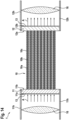
- Figure 2 shows a horizontal section through a beam guiding device 1 according to the invention according to a first embodiment.
- the beam guiding device 1 or the fiber cable 1 essentially consists, along its longitudinal extension direction, of a plurality of fiber elements 10 in the form of flexible fibers 10 or glass fibers 10, each having a fiber core 10a, a fiber cladding 10b surrounding the fiber core 10a, and a fiber coating 10c surrounding the fiber cladding 10b.
- the fiber cores 10a and the fiber claddings 10b are made of quartz glass.
- the fiber coatings 10c are made of a softer material than glass, for example, acrylate, silicone, or polyimide.
- the beam guiding device 1 or the fiber cable 1 has a fiber input element 11 as an elongated cuboid, cf. for example Figure 19 , with an entrance side 11a facing the incoming signal light radiation A and an opposite exit side 11b.
- the corresponding ends of the fiber elements 10 are integrally welded to the surface of the exit side 11b.
- the beam guiding device 1 or the fiber cable 1 has a fiber exit element 12 along the fiber elements 10, to whose entry side 12a the opposite ends of the fiber elements 10 are also welded.
- the fiber exit element 12 is also cuboid-shaped and has an exit side 12b opposite the entry side 12a, through which the signal light radiation A can exit to the outside of the beam guiding device 1.
- the fiber elements 10 can be defined in this way, here in a row, arranged and spaced apart from one another, so that the signal light radiations A enter the beam guiding device 1 parallel to one another through the fiber input element 11 or its input side 11a and there can each pass directly into one of the fiber elements 10.
- the fiber elements 10 guide the signal light radiations A parallel to one another until the signal light radiations A enter the fiber output element 12 together and from there exit parallel to one another via its output side 12b as signal light radiation A into the environment of the beam guiding device 1.
- This can represent a particularly simple possibility of using the signal light radiations A, for example, from the signal light amplifier 5a for the application of the Figure 1 to lead.
- both the entry side 11a of the fiber input element 11 and the exit side 12b of the fiber exit element 12 have an optical coating 13 in the form of an anti-reflection coating 13.
- Figure 3 shows a horizontal section through a beam guiding device 1 according to the invention according to a second embodiment.
- both the exit side 11b of the fiber input element 11 and the entry side 12a of the fiber exit element 12 each have an optical coating 13 in the form of a reflection coating 13 or absorption coating 13 around the fiber elements 10 in order to prevent the unwanted entry of light from these two sides into the fiber input element 11 or into the fiber exit element 12, since the signal light radiation A could be disturbed or influenced thereby.
- Figure 4 shows a horizontal section through a beam guiding device 1 according to the invention according to a third embodiment.
- Figure 5 shows a horizontal section through a beam guiding device 1 according to the invention according to a fourth embodiment.
- the pump light traps 14 are arranged at the ends of the fiber elements 10, so that unwanted pump light from the fiber claddings 10b can be kept directly away from the fiber exit element 12.
- Figure 6 shows a horizontal section through a beam guiding device 1 according to the invention according to a fifth embodiment.
- both the fiber entry element 11 has a recess 11c in the exit side 11b and the fiber exit element 12 has a recess 12c in the entry side 12a, into which the ends of the fiber elements 10 are each embedded and fused there to the fiber entry element 11 and the fiber exit element 12, respectively.
- This can improve the cohesive connection.
- Figure 7 shows a horizontal section through a beam guiding device 1 according to the invention according to a sixth embodiment.
- the fiber exit element 12 corresponds, for example, to the fiber exit element 12 of the first embodiment of the Figure 2
- the fiber entry element 11 has, on the one hand, through-openings 11i that extend through the fiber entry element 11 along the propagation direction of the signal light radiation A and accommodate the corresponding ends of the fiber elements 10. However, they are offset by a predetermined amount into the through-openings 11i, where the ends of the fiber elements 10 are welded to the material of the fiber entry element 11.
- the edge (not labeled) of the fiber entry element 11 extends in a collar-like manner away from the fiber elements 10.
- a spacer element 11g is arranged in a materially bonded manner in the area of the edge or collar, creating a gap 11j or a space 11j, which can be gas-filled, liquid-filled, solid-filled, or vacuum-sealed.
- the spacer element 11g has optical coatings 13 in the form of anti-reflection coatings 13 on both sides.
- the signal light radiation A can pass through the spacer element 11g into the intermediate space 11j, which is facilitated by the two anti-reflection coatings 13 of the spacer element 11g.
- the signal light radiation A can be influenced by the medium located there or by the transition at the boundary layers. The signal light radiation A can then enter directly into the ends of the fiber elements 10 and propagate further there as described above.
- Figure 8 shows a horizontal section through a beam guiding device 1 according to the invention according to a seventh embodiment.
- a spacer element 12g, a gap 12j or a distance 12j and through openings 12i of the fiber exit element 12 are provided on the side of the fiber exit element 12, as previously described with regard to the sixth embodiment of the Figure 7 for the fiber entry element 11.
- the properties and advantages achieved there can alternatively or additionally be applied and implemented to the fiber exit element 12.
- Figure 9 shows a horizontal section through a beam guiding device 1 according to the invention according to an eighth embodiment.
- This embodiment corresponds to the preceding sixth embodiment of the Figure 7 with the difference that the fiber entry element 11 now has recesses 11c instead of the through-openings 11i, which do not receive the ends of the fiber elements 10 completely to the bottom of the recesses 11c, but at a certain distance.
- the continuous surface of the entry side 11a of the fiber entry element 11 has an optical coating 13, which also has an anti-reflection coating 13 to promote the passage of the signal light radiation A.
- Figure 10 shows a horizontal section through a beam guiding device 1 according to the invention according to a ninth embodiment.
- the previously described with regard to the fiber entry element 11 of the Figure 9 described properties and advantages of the fiber entry element 11 to the fiber exit element 12 according to the Figure 8 applied, which can be done alternatively or together.
- Figure 11 shows a horizontal section through a beam guiding device 1 according to the invention according to a tenth embodiment.
- This embodiment also corresponds to the sixth embodiment of the Figure 7 with the difference that the through-openings 11i extend significantly longer without accommodating the fiber elements 10, which only occurs at the edge near the exit side 11b of the fiber inlet element 11.
- the through-openings 11i also have a smaller cross-section than the fiber elements 10.
- Figure 12 shows a horizontal section through a beam guiding device 1 according to the invention according to an eleventh embodiment.
- the previously described with regard to the fiber entry element 11 of the Figure 11 described properties and advantages to the fiber exit element 12 according to the Figures 8 or 10 are applied, which can be done alternatively or together.
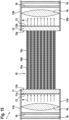
- Figure 13 shows a horizontal section through a beam guiding device 1 according to the invention according to a twelfth embodiment.
- the fiber exit element 12 is based, for example, on the fiber exit element 12 of the first embodiment of the Figure 2
- the exit side 11b of the fiber inlet element 11 has, around the fiber elements 10, an absorption and reflection element 15 that is water-cooled by means of a cooling water flow C in order to reflect unwanted radiation B at this point and to absorb the non-reflected radiation B and dissipate the corresponding thermal energy with the cooling water flow C.
- the fiber exit element 12 In order to reflect and absorb radiation B reflected from a workpiece 2 in a comparable manner, the fiber exit element 12 also has an absorption and reflection element 15 around the fiber elements 10, facing the fiber elements 10, which, however, is only passively air-cooled.
- Figure 14 shows a horizontal section through a beam guiding device 1 according to the invention according to a thirteenth embodiment.
- a pair of holders 11h of the fiber entry element 11 extends toward the signal light radiation A.
- the holders 11h jointly hold, from diametrically opposite sides, an optical element 16 in the form of a converging lens 16, which is traversed by the incoming signal light radiation A before the signal light radiation A then individually enters the fiber elements 10.
- the fiber exit element 12 also has a pair of holders 12h with a converging lens 16 as an optical element 16 in order to also allow the exiting signal light radiations A to pass through this converging lens 16.
- Figure 15 shows a horizontal section through a beam guiding device 1 according to the invention according to a fourteenth embodiment.
- optical elements 16 are arranged one behind the other per pair of holders 11h, 12h.
- the signal light radiations A successively pass through a first microlens array 16, then a second microlens array 16, and then a converging lens 16, before the signal light radiations A each enter one of the fiber elements 10.
- the signal light radiations A successively pass through a converging lens 16, then a first microlens array 16, and then a second microlens array 16, before the signal light radiations A exit to the outside of the beam guiding device 1.
- Figure 16 shows a horizontal section through a beam guiding device 1 according to the invention according to a fifteenth embodiment.
- the fiber exit element 12 again, for example, goes to the fiber exit element 12 of the first embodiment of the Figure 2
- the fiber entry element 11 is formed from a plurality of linearly arranged individual entry elements 11f, with exactly one individual entry element 11f being provided per signal light beam A.
- the individual entry elements 11f are connected to the fiber entry element 11 by means of a carrier 11e.
- the fiber exit element 12 which accordingly has a plurality of linearly arranged individual entry elements 12f, which are connected to the fiber exit element 12 by means of a carrier 12e.
- Figure 17 shows a horizontal section through a beam guiding device 1 according to the invention according to a sixteenth embodiment.
- each of the individual entry elements 11f of the fiber entry element 11 each has an entrance lens 11d in order to focus the incoming signal light radiation A.
- the fiber exit element 12 also has an exit lens 12d per signal light radiation A at its exit point 12b, wherein the fiber exit element 12 in this case is again continuous or integrally formed.
- Figure 18 shows a horizontal section through a beam guiding device 1 according to the invention according to a seventeenth embodiment.
- This seventeenth embodiment is based on the preceding sixteenth embodiment of the Figure 17 , wherein the support 11e of the fiber entry element 11 is bent outward. However, the fiber elements 10 then run parallel to one another again. This allows the signal light radiation A to emanate from a single point and then spread out to enter the respective entry lens 11d of the respective individual entry element 11f of the fiber entry element 11.
- the fiber exit element 12 is designed in a similar manner.
- Figure 19 shows a horizontal section through a beam guiding device 1 according to the invention according to an eighteenth embodiment.
- the fiber elements 10 are arranged linearly in or on the fiber entry element 11, see bottom left in the Figure 19 , but then do not run completely parallel to each other, but change their arrangement in the second dimension in the course of their elongated extension, so that a 2X3 matrix of two fiber elements 10 next to each other and three fiber elements 10 on top of each other arrives at or in the fiber exit element 12, see bottom right in the Figure 19 , and is attached there.
- the fiber elements 10 are arranged closer or denser to one another at the fiber exit element 12. This allows the resulting radiation of the individual signal light beams A to be influenced and, in particular, their power density to be increased.
- Figure 20 shows a horizontal section through a beam guiding device 1 according to the invention according to a nineteenth embodiment.
- Figure 21 shows a horizontal section through a beam guiding device 1 according to the invention according to a twentieth embodiment.
- This embodiment is similar to the previous embodiment of the Figure 20 comparable, except that in this case the second strand of the fiber elements 10 has a rectangular cross-section, see bottom right in the Figure 21 .
- Figure 22 shows a horizontal section through a beam guiding device 1 according to the invention according to a twenty-first embodiment.
- one connecting element 3 or one transition element 3 is provided for each first strand of the fiber elements 10.
- three strands per fiber element 10 are integrally connected to the connecting element 3 from the opposite side, see bottom left in the Figure 22 , so that the signal light radiation A of a first strand of a fiber element 10 is divided into three second strands per fiber element 10.
- the first strands of the fiber elements 10 are arranged next to each other.
- the three times three second strands of the fiber elements 10 are arranged next to and above each other as a 3x3 matrix, wherein the second strands of the fiber elements 10 are arranged one above the other, ie each horizontally, see bottom right in the Figure 22 .
- Figure 23 shows a horizontal section through a beam guiding device 1 according to the invention according to a twenty-second embodiment with a signal radiation source 5.
- each individual signal light beam A is generated by its own signal radiation source 5 in the form of a fiber laser 5 or a diode laser 5.
- the signal radiation sources 5 are controlled or operated by a control unit 6.
- Each signal light beam A is guided by a fiber optic cable to a fiber coupler 4, to a fiber splitter 4, or to a fiber switch 4, where it is decoupled and transmitted to the fiber entry element 11 as described above, i.e., according to one of the exemplary embodiments.
- the fiber entry element 11 is arranged in a housing feedthrough 7a of a housing 7, which accommodates the previously described components.
- six fiber elements 10 are provided, which are arranged next to each other, ie in a row, and are connected to the fiber entry element 11 at a laterally spaced distance from each other, see bottom left in the Figure 23 .
- the fiber elements 10 are guided closer to each other and in two layers of three fiber elements 10 each on top of each other, so that the fiber elements 10 are connected as a 2x3 matrix with the fiber outlet element 12, see bottom right in the Figure 23 , and the signal light radiations A in this constellation are compact and rectangular as resulting signal light radiation A to the outside or from a processing unit 92, cf. Figure 1 , into the environment or towards workpiece 2.
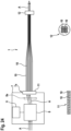
- Figure 24 shows a horizontal section through a beam guiding device 1 according to the invention according to a twenty-third embodiment with a signal radiation source 5.
- the signal light radiations A from a signal light source 5 enter the housing 7 through an open or transparent opening (not shown) and there reach a beam guiding and deflecting unit 8, which can guide the signal light radiations A by means of a deflecting element 8a to different fiber elements 10, which are connected to the fiber entry element 11. More precisely, three signal light radiations A are fed to the beam guiding and deflecting unit 8, and there are nine fiber elements 10, which are arranged next to one another in a row at the fiber entry element 11, see bottom left in the Figure 24 , and form a 3x3 matrix in the course of the beam guiding device 1 at the fiber exit element 12, see bottom right in the Figure 24 .
- the signal light radiations A are thus fed to the left three fiber elements 10 of the fiber entry element 11, the signal light radiations A reach the upper row of fiber elements 10 at the fiber exit element 12. If the three signal light radiations A are fed to the middle three fiber elements 10 of the fiber entry element 11, the signal light radiations A reach the middle row of fiber elements 10 at the fiber exit element 12. If the three signal light radiations A are fed to the right three fiber elements 10 of the fiber entry element 11, the signal light radiations A reach the lower row of fiber elements 10 at the fiber exit element 12. In this way, a comparatively simple control can be achieved by feeding the signal light radiations A to different locations along the beam guiding device 1.
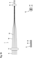
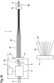
- Figure 25 shows a horizontal section through a beam guiding device 1 according to the invention according to a twenty-fourth embodiment with a signal radiation source 5.
- the representation of the Figure 25 corresponds to the previous presentation of the Figure 24 with the difference that the fiber elements 10 are not straight or not straight from the fiber entry element 11 pointing away, but diagonally, see below in the Figure 25 , which can enable a compact connection or attachment of the fiber elements 10 to the fiber entry element 11 with subsequent expansion of the fiber elements 10.
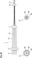
- Figure 26 shows a horizontal section through a beam guiding device 1 according to the invention according to a twenty-fifth embodiment with a signal radiation source 5.
- the representation of the Figure 26 corresponds to the previous presentation of the Figure 25 with the difference that the fiber entry element 11 is curved or concave, so that the signal light radiation A can be forwarded in a star-shaped manner by the deflection element 8a and each enters one of the fiber elements 10 in a straight line.
- the fiber elements 10 then run parallel to each other, see bottom left in the Figure 26 .
- Figure 27 shows a horizontal section through a beam guiding device 1 according to the invention according to a twenty-sixth embodiment with a signal radiation source 5.
- the twenty-sixth embodiment of the Figure 27 The twenty-third embodiment of the Figure 24 whereby by means of the deflection element 8a also other constellations or combinations of fiber elements 10 can be fed with the signal light radiation A, see bottom right in the Figure 27 , so that not only straight horizontal signal light radiations A can be generated at the output of the fiber exit element 12, see bottom right center in the Figure 27 , but also a diagonal gradient, see bottom right top of the Figure 27 . All fiber elements 10 can also be fed simultaneously, see bottom right in the Figure 27 if sufficient signal light radiation A is provided.
Landscapes
- Physics & Mathematics (AREA)
- General Physics & Mathematics (AREA)
- Optics & Photonics (AREA)
- Optical Couplings Of Light Guides (AREA)
Applications Claiming Priority (1)
| Application Number | Priority Date | Filing Date | Title |
|---|---|---|---|
| DE102023133492.1A DE102023133492A1 (de) | 2023-11-30 | 2023-11-30 | Strahlführungsvorrichtung zur Führung von Signallichtstrahlung |
Publications (1)
| Publication Number | Publication Date |
|---|---|
| EP4567486A1 true EP4567486A1 (fr) | 2025-06-11 |
Family
ID=93607926
Family Applications (1)
| Application Number | Title | Priority Date | Filing Date |
|---|---|---|---|
| EP24214247.9A Pending EP4567486A1 (fr) | 2023-11-30 | 2024-11-20 | Dispositif de guidage de faisceau pour guider un rayonnement lumineux de signal |
Country Status (3)
| Country | Link |
|---|---|
| US (1) | US20250180811A1 (fr) |
| EP (1) | EP4567486A1 (fr) |
| DE (1) | DE102023133492A1 (fr) |
Citations (7)
| Publication number | Priority date | Publication date | Assignee | Title |
|---|---|---|---|---|
| DE4301716A1 (fr) * | 1992-02-04 | 1993-08-05 | Hitachi Ltd | |
| EP0590268B1 (fr) * | 1985-03-22 | 1998-07-01 | Massachusetts Institute Of Technology | Sonde comprenant des fibres optiques destiné à l'analyse spectrale de tissus |
| US5852699A (en) * | 1996-09-03 | 1998-12-22 | Lissotschenko; Vitaly | Fiber optical light transmission device for transmitting energy |
| US20180292610A1 (en) * | 2017-04-10 | 2018-10-11 | Fanuc Corporation | Optical fiber cable unit |
| US20200408992A1 (en) * | 2018-03-12 | 2020-12-31 | Furukawa Electric Co., Ltd. | Optical fiber bundle with beam overlapping mechanism |
| WO2022129225A2 (fr) * | 2020-12-16 | 2022-06-23 | FiberBridge Photonics GmbH | Élément de sortie en fibres |
| US11712765B2 (en) * | 2017-10-26 | 2023-08-01 | General Electric Company | Diode laser fiber array for contour of powder bed fabrication or repair |
Family Cites Families (7)
| Publication number | Priority date | Publication date | Assignee | Title |
|---|---|---|---|---|
| DE3650688T2 (de) * | 1985-03-22 | 1999-03-25 | Massachusetts Institute Of Technology, Cambridge, Mass. | Faseroptisches Sondensystem zur spektralen Diagnose von Gewebe |
| WO1998041849A1 (fr) * | 1997-03-14 | 1998-09-24 | Rosemount Analytical Inc. | Appareil et procede ameliore de regulation de la retrodiffusion de rayleigh |
| DE10344169A1 (de) * | 2003-09-22 | 2005-05-04 | Fraunhofer Ges Forschung | Konfokales Endomikroskop |
| JP5430278B2 (ja) * | 2009-08-04 | 2014-02-26 | 株式会社ミツトヨ | 光電式エンコーダ |
| DE102010033427A1 (de) * | 2010-08-04 | 2012-02-09 | Karl Storz Gmbh & Co. Kg | Endoskop mit einstellbarer Blickrichtung |
| US12498521B2 (en) * | 2019-06-21 | 2025-12-16 | FiberBridge Photonics GmbH | Fiber exit element |
| DE102022101915B3 (de) * | 2022-01-27 | 2023-03-16 | FiberBridge Photonics GmbH | Faseraustrittselement |
-
2023
- 2023-11-30 DE DE102023133492.1A patent/DE102023133492A1/de active Pending
-
2024
- 2024-11-20 EP EP24214247.9A patent/EP4567486A1/fr active Pending
- 2024-11-26 US US18/960,194 patent/US20250180811A1/en active Pending
Patent Citations (7)
| Publication number | Priority date | Publication date | Assignee | Title |
|---|---|---|---|---|
| EP0590268B1 (fr) * | 1985-03-22 | 1998-07-01 | Massachusetts Institute Of Technology | Sonde comprenant des fibres optiques destiné à l'analyse spectrale de tissus |
| DE4301716A1 (fr) * | 1992-02-04 | 1993-08-05 | Hitachi Ltd | |
| US5852699A (en) * | 1996-09-03 | 1998-12-22 | Lissotschenko; Vitaly | Fiber optical light transmission device for transmitting energy |
| US20180292610A1 (en) * | 2017-04-10 | 2018-10-11 | Fanuc Corporation | Optical fiber cable unit |
| US11712765B2 (en) * | 2017-10-26 | 2023-08-01 | General Electric Company | Diode laser fiber array for contour of powder bed fabrication or repair |
| US20200408992A1 (en) * | 2018-03-12 | 2020-12-31 | Furukawa Electric Co., Ltd. | Optical fiber bundle with beam overlapping mechanism |
| WO2022129225A2 (fr) * | 2020-12-16 | 2022-06-23 | FiberBridge Photonics GmbH | Élément de sortie en fibres |
Also Published As
| Publication number | Publication date |
|---|---|
| US20250180811A1 (en) | 2025-06-05 |
| DE102023133492A1 (de) | 2025-06-05 |
Similar Documents
| Publication | Publication Date | Title |
|---|---|---|
| EP2596901B1 (fr) | Dispositif de rayonnement optique pour une installation destinée à la fabrication de pièces à usiner tridimensionnelles par rayonnement de couches de pulvérisation d'une poudre de matière brute avec un rayonnement laser | |
| DE2745940B2 (de) | Optischer Übertragungskörper | |
| DE102007057868A1 (de) | Vorrichtung zur Strahlformung | |
| EP4431990A2 (fr) | Élément de sortie en fibres | |
| EP2184139B1 (fr) | Dispositif de traitement en 3D hautement dynamique d'une pièce usinée à l'aide d'un rayon laser | |
| EP0923749B1 (fr) | Dispositif de transmission de lumiere | |
| DE102012202177B3 (de) | Freistrahloptische Faser-zu-Faser-Kopplungsvorrichtung | |
| EP4567486A1 (fr) | Dispositif de guidage de faisceau pour guider un rayonnement lumineux de signal | |
| WO2022171576A1 (fr) | Fibre à noyau creux permettant la transmission de la lumière laser | |
| DE102020113731B4 (de) | Glasfaser und Glasfaserprodukt | |
| EP2407807A2 (fr) | Dispositif de fibre optique et dispositif laser doté d'un tel dispositif de fibre optique | |
| DE102022101915B3 (de) | Faseraustrittselement | |
| WO2000014582A2 (fr) | Embout pour fibres optiques | |
| WO2022129225A2 (fr) | Élément de sortie en fibres | |
| EP0976184A2 (fr) | Dispositif laser | |
| DE29816108U1 (de) | Abschlußstück für Lichtleitfasern | |
| DE19927167A1 (de) | Koppelelement zur Kopplung hochintensiver Lichtstrahlung und Verfahren zu dessen Herstellung sowie Anordnung aus Koppelelementen zur Kopplung hochintensiver Lichtstrahlung | |
| DE10062454B4 (de) | Verfahren und Vorrichtung zur Überlagerung von Strahlenbündeln | |
| DE102019116812A1 (de) | Bearbeitungsvorrichtung für Glasfasern | |
| DE102020008266B4 (de) | Glasfaser und Glasfaserprodukt | |
| EP0667545B1 (fr) | Dispositif pour adapter différentes distributions de champs de faisceaux lumineux | |
| DE102021103603B4 (de) | Verfahren zum Bearbeiten einer optischen Faser, optische Faser sowie Kopplungsanordnung | |
| DE102022129645A1 (de) | Glasfaseroptisches Bauteil | |
| WO2008128678A1 (fr) | Dispositif et procédé d'injection de lumière dans une fibre | |
| DE10054552A1 (de) | Kopplungseinrichtung zur optischen Kopplung versetzt zueinander angeordneter optischer Sende- und Empfangselemente |
Legal Events
| Date | Code | Title | Description |
|---|---|---|---|
| PUAI | Public reference made under article 153(3) epc to a published international application that has entered the european phase |
Free format text: ORIGINAL CODE: 0009012 |
|
| STAA | Information on the status of an ep patent application or granted ep patent |
Free format text: STATUS: THE APPLICATION HAS BEEN PUBLISHED |
|
| AK | Designated contracting states |
Kind code of ref document: A1 Designated state(s): AL AT BE BG CH CY CZ DE DK EE ES FI FR GB GR HR HU IE IS IT LI LT LU LV MC ME MK MT NL NO PL PT RO RS SE SI SK SM TR |
|
| STAA | Information on the status of an ep patent application or granted ep patent |
Free format text: STATUS: REQUEST FOR EXAMINATION WAS MADE |
|
| 17P | Request for examination filed |
Effective date: 20251211 |