EP4574645A1 - Système de commande de propulsion marine - Google Patents
Système de commande de propulsion marine Download PDFInfo
- Publication number
- EP4574645A1 EP4574645A1 EP23219259.1A EP23219259A EP4574645A1 EP 4574645 A1 EP4574645 A1 EP 4574645A1 EP 23219259 A EP23219259 A EP 23219259A EP 4574645 A1 EP4574645 A1 EP 4574645A1
- Authority
- EP
- European Patent Office
- Prior art keywords
- drive unit
- unit
- propellers
- control system
- marine
- Prior art date
- Legal status (The legal status is an assumption and is not a legal conclusion. Google has not performed a legal analysis and makes no representation as to the accuracy of the status listed.)
- Granted
Links
Images


Classifications
-
- B—PERFORMING OPERATIONS; TRANSPORTING
- B63—SHIPS OR OTHER WATERBORNE VESSELS; RELATED EQUIPMENT
- B63H—MARINE PROPULSION OR STEERING
- B63H20/00—Outboard propulsion units, e.g. outboard motors or Z-drives; Arrangements thereof on vessels
- B63H20/08—Means enabling movement of the position of the propulsion element, e.g. for trim, tilt or steering; Control of trim or tilt
- B63H20/12—Means enabling steering
Definitions
- the disclosure relates generally to a propulsion control system.
- the disclosure relates to a marine propulsion control system for a marine vessel.
- the disclosure can be applied to marine vessels, such as water crafts, motorboats, work boats, sport vessels, boats, ships, among other vessel types.
- marine vessels such as water crafts, motorboats, work boats, sport vessels, boats, ships, among other vessel types.
- the disclosure may be described with respect to a particular marine vessel, the disclosure is not restricted to any particular marine vessel.
- Propulsion control systems for marine vessels are known. These propulsions systems having a drive unit which may be operated in different positions so as to improve the marine vessel's performance and energy consumption to power the drive unit. These known systems do not take into account where the marine vessel is operating both in normal draught and in reduced draught situations, as well as in other circumstances and conditions of the marine vessel.
- the drive unit having one or more propellers propelling the marine vessel in normal manner.
- persons and/or equipment are in the water around the marine vessel for bathing and swimming which may have the severe consequence that the person and/or equipment may come in contact with the one or more propellers.
- a marine propulsion control system for a marine vessel comprising a drive unit being adapted to be connected with the marine vessel, the drive unit comprises an upper part being pivotable connected with the marine vessel and a lower part having one or more propellers providing a thrust force, the lower part is rotatable in relation to the upper part, an input unit configured to obtain an activation message indicative of an operation mode for the drive unit, a control unit being operatively connected with the drive unit and the input unit, the control unit is configured to control the drive unit on basis of the activation message obtained from the input unit, wherein the control unit, based on at least the activation message, is configured to control the drive unit within different predetermined operation modes, wherein one of the predetermined operation modes is a swim mode in which the control unit is configured to rotate the lower part of the drive unit so that the one or more propellers is/are facing forward in a position of minimum 90 degrees compared to a rearward facing position of the one or more propellers, wherein the control unit is
- the first aspect of the disclosure may seek to solve the disadvantages with the prior solutions and especially the sometime missing security while operating the marine vessel in different situations.
- a technical benefit may include providing a propulsion control system having a drive unit with a lower part which is rotatably connected with an upper part, whereby the control unit ensures that the one or more propellers are rotated to a position with the one or more propellers at least facing forward in a position of minimum 90 degrees compared to an aft facing position of the one or more propellers when the control unit has obtained a swim mode activation message.
- the risk for damaging persons bathing and swimming around the marine vessel is minimized and a higher security is obtained while operating the marine vessel during swimming and bathing.
- control unit is operatively connected with the tilt and trim arrangement.
- a technical benefit may include that the trim and tilt of the drive unit may be performed and controlled by the control unit.
- the activation message is activated by an operator or captain and/or is an automatically generated activation message.
- a technical benefit may include providing different possibilities for activating the activation message.
- the automatically generated activation message is sensor data obtained from one or more sensor(s).
- a technical benefit may include that the sensors may detect different objects in the surrounding of the marine vessel or other parameters and based on these detections an automatically generated activation message may be provided to the control unit.
- the risk for human failure or unintended operation of the propulsion control system minimized.
- the one or more sensors is/are configured to detect one or more condition(s) of the marine vessel, the drive unit and/or a surrounding of the marine vessel.
- a technical benefit may include that the sensors may detect different conditions of the marine vessel, drive unit and/or surroundings or other parameters and based on these detections an automatically generated activation message may be provided to the control unit for enhanced control and security. Hereby is the risk for human failure or unintended operation of the propulsion control system minimized.
- one of the predetermined operation modes is a normal/high speed mode in which the control unit is configured to control the drive unit, a steering unit, and/or the tilt and trim arrangement so that the trim of the drive unit and steering is set with limitations and no tilt capability of the drive unit.
- a technical benefit may include that it is ensured that the risk for human failure or unintended operation of the propulsion control system minimized.
- the limitation is that the trim of the drive unit cannot exceed ⁇ 10 degrees, preferably ⁇ 5 degrees compared to neutral trim, and that rotation of the lower part of the drive unit is limited to 30 degrees.
- a technical benefit may include that it is ensured that restriction for operating the marine vessel is provided, which again minimizes the risk for human failure or unintended operation of the propulsion control system.
- one of the predetermined operation modes is a slow speed mode in which the control unit is configured to control the drive unit, a steering unit, and/or the tilt and trim arrangement so that the trim of the drive unit is free, unlimited steering up to 360 degrees.
- a technical benefit may that it is ensured that the risk for human failure or unintended operation of the propulsion control system minimized.
- FIGS. 1-3 is an exemplary view of a marine propulsion control system 1 for a marine vessel 100 according to an example.
- the marine propulsion control system 1 comprises a drive unit 3 comprising an upper part 20 and a lower part 21 , the upper part 20 being pivotable in relation to the marine vessel 100 and the lower part 21 is rotatably connected with the upper part 20 .
- the lower part 21 having one or more propellers providing a thrust force.
- the lower part 21 comprises in the present example a first propeller 13a , and a second propeller 13b .
- the upper part 20 of the drive unit 3 may be moved in relation to the transom 101 of the marine vessel 100 so that the drive unit may be tilted in and out of the water and/or trimmed to an intended trim angle in the water. Hence, the upper part 20 may be moved in relation to the marine vessel 100 .
- the lower part 21 is rotatably connected with the upper part 20 whereby the lower part may be rotated in relation to the upper part 20 around an axis R .
- the lower part 21 is configured to follow the movements of the upper part 20 in relation to the marine vessel 100 .
- the marine propulsion control system 1 also comprises an input unit 22 configured to obtain an activation message indicative of an operation mode for the drive unit 3 , and a control unit 23 being operatively connected with the drive unit 3 and the input unit 22 , the control unit 23 is configured to control the drive unit 3 on basis of the activation message obtained from the input unit 22.
- the control unit 23 based on at least the activation message, is configured to control the drive unit 3 within different predetermined operation modes.
- One of the predetermined operation modes is a swim mode in which the control unit 23 is configured to rotate the lower part 21 of the drive unit 3 so that the one or more propellers 13a , 13b is/are facing forward in a position of minimum 90 degrees compared to a rearward facing position of the one or more propellers.
- the control unit 23 is configured to ensure no thrust force and/or rotation of the one or more propellers 13a , 13b in the swim mode.
- the input unit 22 may be arranged at the marine vessel 100 or at the drive unit 3 , in the example in FIG. 1 , the input unit 22 is arranged at the marine vessel 100.
- the control unit may also be arranged at the marine vessel 100 or at the drive unit 3 , in the example in FIG. 1 the input unit 22 is arranged at the marine vessel 100 .
- control unit 23 in response to obtaining a swim mode activation message from the input unit 22 , is configured to rotate the lower part 21 to a position with the one or more propellers 13a , 13b at least facing forward in a position of minimum 90 degrees compared to an aft facing position of the one or more propellers.
- the swim mode activation message may be activated when persons onboard the marine vessel 100 would like to swim around the marine vessel 100 , for instance by using the bathing platform 103 arranged at the transom 101 of the marine vessel 100 .
- the propellers 13a , 13b are configured to be a pushing drive, hence in normal operation they are pushing the marine vessel 100 .
- the first and second propellers 13a , 13b are arranged after the lower part 21 so that when rotated they will push the lower part 21 and thereby push the marine vessel.
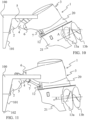
- the drive unit 3 may be trimmed in different angles for optimizing the angle of thrust for the propellers 13a , 13b during different operating conditions. In FIG. 1 , the drive unit 3 is positioned in neutral trim where the angle of thrust of the first propeller 13a and the second propeller 13b are zero.
- the drive unit 3 has been pivoted in a clockwise direction in relation to the marine vessel so as to position the drive unit 3 in a negative trim having a negative angle of thrust A of the first propeller 13a and the second propeller 13b .
- the drive unit 3 has been pivoted in an anticlockwise direction in relation to the marine vessel 100 so as to position the drive unit 3 in a positive trim having a positive angle of thrust A of the first propeller 13a and the second propeller 13b .
- FIG. 4 is the marine propulsion control system 1 of FIG. 1 where the lower part 21 has been rotated around the axis R in relation to the upper part 20 .
- the control unit 23 in response to obtaining a swim mode activation message from the input unit 22 , has rotated the lower part 21 to a position with the one or more propellers 13a , 13b facing forward towards the marine vessel 100 .
- the first and second propellers 13a , 13b have been rotated 180 degrees compared to their position shown in FIG. 1 .
- the control unit 23 may rotate the first and second propellers 13a, 13b minimum 90 degrees compared to an aft facing position of the one or more propellers 13a , 13b .
- the control unit 23 may be configured to lower the drive unit 3 to its lowermost position so that the swimmers are further protected from the one or more propellers 13a , 13b.
- the activation message is activated by an operator or captain on the marine vessel 100 and/or is an automatically generated activation message.
- the operator or captain may activate the beach mode activating message at the input unit 22
- the operator or captain may activate the swim mode activating message at the input unit 22 .
- the drive unit 3 may be locked in the swim mode until swim mode activation message is deactivated by the operator or captain.
- the drive unit 3 is configured to be started with a special acknowledgement operation when in swim mode, such as unlocking by a physical or digital key.
- a special acknowledgement operation when in swim mode, such as unlocking by a physical or digital key.
- control unit 23 in response to obtaining a beach mode activation message from the input unit 22 , has rotated the lower part 21 with the one or more propellers 13a , 13b facing aft in relation to the marine vessel 100.
- the drive unit 3 has in the shown example been translated rearward as the same time it has been raised.
- FIG. 9 the drive unit of FIG. 7 is still in the beach mode having the first and second propeller 13a , 13b facing aft.
- the control unit 23 has brought the drive unit 3 to a lower draught than shown in FIG. 8 .
- FIG. 10 is an exemplary view of a propulsion control system 1 for a marine vessel 100 according to an example.
- the propulsion control system 1 comprises a transom bracket 2 configured to be connected with a transom 101 of the marine vessel 100 , and a drive unit 3 .
- the drive unit 3 is arranged to be moved in relation to the transom bracket 2 for moving the drive unit 3 in the water and out of the water.
- the drive unit 3 comprises an upper part 20 and a lower part 21 , the upper part 20 being pivotable in relation to the marine vessel 100 and the lower part 21 is rotatably connected with the upper part 20 , the lower part 21 comprises in the present example a first propeller 13a , and a second propeller 13b .
- the drive unit 3 is connected with the transom bracket 2 via a connecting arm 4 having a first pivot joint 5 connected with the transom bracket 2 and a second pivot joint 6 connected with the drive unit 3 .
- the drive unit 3 is configured to be moved in the water and out of the water by the connecting arm 4 pivots around the first pivot joint 5 or the drive unit 3 pivots around the second pivot joint 6 or the connecting arm 4 and the drive unit 3 pivot around both pivot joints 5 , 6.
- the drive unit 3 may be moved up and down and trimmed.
- the drive unit 3 has been moved rearwards while it has been tilted up by rotating the connecting arm 5 around the first pivot joint 5 .
- the drive unit 3 has been rotated around the second pivot joint 6 of the connecting arm 4 so that a positive trim angle A is obtained of the drive unit 3 .
- the drive unit 3 is configured to be moved by the drive unit is pivoted around the second pivot joint 6 in a clockwise direction or an anticlockwise direction independently of any pivoting of the connecting arm 4 around the first pivot joint 5.
- the drive unit 3 has been pivoted in an anticlockwise direction around the second pivot joint 6 .
- the drive unit 3 is configured to be moved by the connecting arm 4 is pivoted around the first pivot joint 5 in a clockwise direction or an anticlockwise direction at the same time as the drive unit 3 is pivoted around the second pivot joint 6 in a clockwise direction or an anticlockwise direction.
- the connecting arm 4 has pivoted in an anticlockwise direction around the first pivot joint 5 and the drive unit 3 has been pivoted in an anticlockwise direction around the second pivot joint 6 .
- the drive unit 3 may be trimmed in different trim positions by pivoting the drive unit 3 around the second pivot joint 6 and the position in the water of the drive unit may at the same time been obtained by pivoting the connecting arm 4 around the first pivot joint 5 . Freedom to position the drive unit 3 in relation the transom bracket 2 is obtained. Additionally, the drive unit 3 may be moved up and down as well as translated rearwards in relation to the transom bracket 2 while maintaining an improved angle of thrust A .
- the drive unit 3 comprises one or more propellers.
- the drive unit 3 comprises the first propeller 13a and a second propeller 13b .
- the first propeller 13a and the second propeller 13b are configured to push the marine vessel 100 in a forward motion of the marine vessel 100 .
- the one or more propellers are configured to pull the marine vessel 100 in a forward motion of the marine vessel.
- the first propeller 13a and second propeller 13b have an angle of thrust A , indicated by the angle between the dotted line and the arrow in FIG. 10 .
- the drive unit 3 has been pivoted in the anticlockwise direction around the second pivot joint 6 so that a positive trim angle and thereby angle of thrust A for the first propeller 13a and the second propeller 13b.
- the first propeller 13a is arranged to be counter-rotating compared to the second propeller 13b .
- the drive unit 3 may be positioned freely in relation to a transom bracket 2 and thereby the transom 101 of the marine vessel 100 both in rotation but also vertical movements as well as horizontal movements.
- a linear actuator 7 is arranged between the connecting arm 4 and the drive unit 3 .
- the linear actuator 7 is configured to pivot the drive unit 3 around the second pivot joint 6 in either the clockwise direction or the anticlockwise direction and thereby a trim angle of the drive unit 3 and the angle of thrust may be set in relation to the circumstance.
- the linear actuator 7 is connected with the drive unit 3 in a distance below the second pivot joint 6 and is connected with the drive unit 3 via a drive pivot joint 12 so that it is ensured that the linear actuator 7 transfer force to pivot the drive unit 3 around the second pivot joint 6.
- the drive unit 3 has been tilted further up by rotating the connecting arm 4 around the first pivot joint 5 compared to in FIG. 10 .
- the drive unit 3 has been rotated in anticlockwise direction around the second pivot joint 6 of the connecting arm 4 so that an improved angle of thrust A of the first propeller 13a and the second propeller 13b is obtained even though the drive unit 3 has been raised to a positon being higher than a bottom 102 of the marine vessel 100 .
- the drive unit 3 may be trimmed to an optimum position irrespective of the operating in shallow waters since the bottom 102 of the marine vessel 100 is protecting the drive unit 3 and its propellers against impact.
- the connecting arm 4 in FIG. 11 has been pivoted further around the first pivot joint 5 in an anticlockwise direction thereby tilting the drive unit 3 upwards.
- the connecting arm 4 is configured to be pivoted around the first pivot point 5 in maximum 200 degrees, preferably maximum 180 degrees.
- FIG. 21 is another view of an example.
- FIG. 21 shows a marine propulsion control system 1 for a marine vessel 100 , comprising a drive unit 3 being connected with the marine vessel, the drive unit 3 comprises an upper part 20 being pivotable connected with the marine vessel and a lower part 21 having one or more propellers 13a , 13b providing a thrust force, the lower part 21 is rotatable in relation to the upper part 20 , an input unit 22 configured to obtain an activation message indicative of an operation mode for the drive unit 3 , a control unit 23 being operatively connected with the drive unit 3 and the input unit 22 , the control unit 23 is configured to control the drive unit 3 on basis of the activation message obtained from the input unit 22 , wherein the control unit 23 , based on at least the activation message, is configured to control the drive unit 3 within different predetermined operation modes, wherein one of the predetermined operation modes is a swim mode in which the control unit 23 is configured to rotate the lower part 21 of the drive unit 3 so that the one or more propellers 13
- Example 32 The marine propulsion control system ( 1 ) of any of the examples 1-31, wherein the control unit ( 23 ) is configured to issue a notification that it is safe to swim around the drive unit ( 3 ) when the lower part ( 21 ) of the drive unit ( 3 ) has been rotated the position with the one or more propellers ( 13a , 13b) at least facing forward in the position of minimum 90 degrees compared to the aft facing position of the one or more propellers, and the one or more propellers are locked.
- Example 34 The marine propulsion control system ( 1 ) of example 9, wherein the one or more sensor(s) ( 24 ) is/are configured to detect a draught around the marine vessel and based on the detected draught activates the shallow water/beach mode activating message.
- Example 35 The marine propulsion control system ( 1 ) of example 9, wherein the one or more sensor(s) ( 24 , 40 ) is/are configured to detect an obstacle and/or humans or animals around the marine vessel ( 100 ) and based on the detection activates the swim mode activating message.
- Example 36 The marine propulsion control system ( 1 ) of example 9, wherein the one or more sensor(s) ( 24 , 40 ) is/are configured to detect obstacles and/or humans or animals in the vicinity of the one or more propellers ( 13a , 13b).
- Example 37 The marine propulsion control system ( 1 ) of any of the examples 9-36, wherein the one or more sensors ( 24 , 25 , 40 ) are operatively connected with the control unit ( 23 ).
- Example 38 The marine propulsion control system ( 1 ) of any of the examples 9-37, wherein the sensor ( 24 , 25 , 40 ) is a proximity sensor, a LiDAR sensor, a Sonar sensor, a speed log, a torque sensor, a depth sensor, power consumption sensor, a basic on/off switch sensor, a gate sensor, or similar.
- the sensor ( 24 , 25 , 40 ) is a proximity sensor, a LiDAR sensor, a Sonar sensor, a speed log, a torque sensor, a depth sensor, power consumption sensor, a basic on/off switch sensor, a gate sensor, or similar.
- Example 39 The marine propulsion control system ( 1 ) of any of the examples 1-38, wherein the control unit ( 23 ) is configured to issue a notification that the drive unit ( 3 ) is in the shallow water/beach mode when the lower part ( 21 ) of the drive unit ( 3 ) has been rotated the position with the one or more propellers facing aft in relation to the marine vessel, whereby the drive unit can operate the marine vessel in shallow water.
- Example 40 The marine propulsion control system ( 1 ) of any of the examples 1-39, wherein the control unit ( 23 ) is configured is issue one or more indications for indicating when the swim mode is active and thereby it is safe to swim around the drive unit ( 3 ).
- Example 41 The marine propulsion control system ( 1 ) of any of the examples 1-40, wherein at least the swim mode is associated with a green light arranged in connection to a bathing platform of the marine vessel.
- Example 77 The method of any of the examples 68-76, further comprising
Landscapes
- Chemical & Material Sciences (AREA)
- Engineering & Computer Science (AREA)
- Combustion & Propulsion (AREA)
- Mechanical Engineering (AREA)
- Ocean & Marine Engineering (AREA)
- Toys (AREA)
Priority Applications (3)
| Application Number | Priority Date | Filing Date | Title |
|---|---|---|---|
| EP23219259.1A EP4574645B1 (fr) | 2023-12-21 | 2023-12-21 | Système de commande de propulsion marine |
| JP2024146578A JP2025036309A (ja) | 2023-09-01 | 2024-08-28 | 船舶推進制御システム |
| US18/817,684 US20250074566A1 (en) | 2023-09-01 | 2024-08-28 | Marine propulsion control system |
Applications Claiming Priority (1)
| Application Number | Priority Date | Filing Date | Title |
|---|---|---|---|
| EP23219259.1A EP4574645B1 (fr) | 2023-12-21 | 2023-12-21 | Système de commande de propulsion marine |
Publications (2)
| Publication Number | Publication Date |
|---|---|
| EP4574645A1 true EP4574645A1 (fr) | 2025-06-25 |
| EP4574645B1 EP4574645B1 (fr) | 2026-01-28 |
Family
ID=89308569
Family Applications (1)
| Application Number | Title | Priority Date | Filing Date |
|---|---|---|---|
| EP23219259.1A Active EP4574645B1 (fr) | 2023-09-01 | 2023-12-21 | Système de commande de propulsion marine |
Country Status (1)
| Country | Link |
|---|---|
| EP (1) | EP4574645B1 (fr) |
Citations (4)
| Publication number | Priority date | Publication date | Assignee | Title |
|---|---|---|---|---|
| BE466601A (fr) * | 1942-08-06 | 1946-08-31 | Murray & Tregurtha. Inc | Mécanisme d'hélice "hors bord" pour péniches, chalands, etc. |
| FR1054252A (fr) * | 1951-12-19 | 1954-02-09 | Perfectionnements apportés aux groupes moteurs marins du type hors-bord | |
| US8622777B1 (en) * | 2011-06-09 | 2014-01-07 | Brunswick Corporation | Systems and methods for controlling trim and maneuvering a marine vessel |
| US20210114703A1 (en) * | 2019-10-21 | 2021-04-22 | Steering Solutions Ip Holding Corporation | Electric steering assembly for marine craft auxiliary outboard motor |
-
2023
- 2023-12-21 EP EP23219259.1A patent/EP4574645B1/fr active Active
Patent Citations (4)
| Publication number | Priority date | Publication date | Assignee | Title |
|---|---|---|---|---|
| BE466601A (fr) * | 1942-08-06 | 1946-08-31 | Murray & Tregurtha. Inc | Mécanisme d'hélice "hors bord" pour péniches, chalands, etc. |
| FR1054252A (fr) * | 1951-12-19 | 1954-02-09 | Perfectionnements apportés aux groupes moteurs marins du type hors-bord | |
| US8622777B1 (en) * | 2011-06-09 | 2014-01-07 | Brunswick Corporation | Systems and methods for controlling trim and maneuvering a marine vessel |
| US20210114703A1 (en) * | 2019-10-21 | 2021-04-22 | Steering Solutions Ip Holding Corporation | Electric steering assembly for marine craft auxiliary outboard motor |
Also Published As
| Publication number | Publication date |
|---|---|
| EP4574645B1 (fr) | 2026-01-28 |
Similar Documents
| Publication | Publication Date | Title |
|---|---|---|
| US20220212768A1 (en) | System for controlling marine craft with steerable drives | |
| US20170158297A1 (en) | Watercraft protection systems and methods | |
| JPH064437B2 (ja) | 舶用推進装置 | |
| US7267588B1 (en) | Selectively lockable marine propulsion devices | |
| JP2024060160A (ja) | 船舶推進システムおよび船舶 | |
| JP2024060162A (ja) | 船舶推進システムおよび船舶 | |
| EP4574645A1 (fr) | Système de commande de propulsion marine | |
| US20250074566A1 (en) | Marine propulsion control system | |
| EP4516656A1 (fr) | Système de propulsion marine | |
| CN115071942B (zh) | 船用舷外机、船舶及船用舷外机的控制方法 | |
| EP4458664A1 (fr) | Système de propulsion de sport nautique pour navire de sport nautique | |
| US20090163090A1 (en) | Automatic trim apparatus | |
| US12420899B2 (en) | Marine propulsion system and marine vessel | |
| EP4566936A1 (fr) | Système de propulsion | |
| EP4461635A1 (fr) | Système de propulsion pour un navire | |
| US20240343370A1 (en) | Propulsion system for a marine vessel | |
| EP4574644A1 (fr) | Système de propulsion marine | |
| JP2022160036A (ja) | 船舶の航行システム | |
| EP4461634A1 (fr) | Système de propulsion avec actionneur linéaire relevable | |
| US20240343365A1 (en) | Propulsion system for a marine vessel and a use of a slip clutch assembly | |
| JP2026002253A (ja) | 船舶の制御装置および船舶 | |
| EP4458663A1 (fr) | Système de propulsion pour un navire | |
| AU2009100424A4 (en) | Method & Apparatus for Assisting Manoeuvring a Boat Around a Dock | |
| CN118790405A (zh) | 具有可移动游泳平台的船用推进系统 | |
| JPH10218097A (ja) | ヨットの操舵装置 |
Legal Events
| Date | Code | Title | Description |
|---|---|---|---|
| PUAI | Public reference made under article 153(3) epc to a published international application that has entered the european phase |
Free format text: ORIGINAL CODE: 0009012 |
|
| STAA | Information on the status of an ep patent application or granted ep patent |
Free format text: STATUS: REQUEST FOR EXAMINATION WAS MADE |
|
| 17P | Request for examination filed |
Effective date: 20241008 |
|
| AK | Designated contracting states |
Kind code of ref document: A1 Designated state(s): AL AT BE BG CH CY CZ DE DK EE ES FI FR GB GR HR HU IE IS IT LI LT LU LV MC ME MK MT NL NO PL PT RO RS SE SI SK SM TR |
|
| REG | Reference to a national code |
Ref country code: DE Ref legal event code: R079 Free format text: PREVIOUS MAIN CLASS: B63H0020100000 Ipc: B63H0020120000 Ref country code: DE Ref legal event code: R079 Ref document number: 602023011289 Country of ref document: DE Free format text: PREVIOUS MAIN CLASS: B63H0020100000 Ipc: B63H0020120000 |
|
| GRAP | Despatch of communication of intention to grant a patent |
Free format text: ORIGINAL CODE: EPIDOSNIGR1 |
|
| STAA | Information on the status of an ep patent application or granted ep patent |
Free format text: STATUS: GRANT OF PATENT IS INTENDED |
|
| RIC1 | Information provided on ipc code assigned before grant |
Ipc: B63H 20/12 20060101AFI20250723BHEP |
|
| INTG | Intention to grant announced |
Effective date: 20250804 |
|
| GRAS | Grant fee paid |
Free format text: ORIGINAL CODE: EPIDOSNIGR3 |
|
| GRAA | (expected) grant |
Free format text: ORIGINAL CODE: 0009210 |
|
| STAA | Information on the status of an ep patent application or granted ep patent |
Free format text: STATUS: THE PATENT HAS BEEN GRANTED |
|
| AK | Designated contracting states |
Kind code of ref document: B1 Designated state(s): AL AT BE BG CH CY CZ DE DK EE ES FI FR GB GR HR HU IE IS IT LI LT LU LV MC ME MK MT NL NO PL PT RO RS SE SI SK SM TR |
|
| REG | Reference to a national code |
Ref country code: CH Ref legal event code: F10 Free format text: ST27 STATUS EVENT CODE: U-0-0-F10-F00 (AS PROVIDED BY THE NATIONAL OFFICE) Effective date: 20260128 Ref country code: GB Ref legal event code: FG4D |
|
| REG | Reference to a national code |
Ref country code: DE Ref legal event code: R096 Ref document number: 602023011289 Country of ref document: DE |
|
| REG | Reference to a national code |
Ref country code: IE Ref legal event code: FG4D |