EP4576573A1 - Haltevorrichtung für piezoelektrischen resonator und stromwandler damit - Google Patents
Haltevorrichtung für piezoelektrischen resonator und stromwandler damit Download PDFInfo
- Publication number
- EP4576573A1 EP4576573A1 EP24222410.3A EP24222410A EP4576573A1 EP 4576573 A1 EP4576573 A1 EP 4576573A1 EP 24222410 A EP24222410 A EP 24222410A EP 4576573 A1 EP4576573 A1 EP 4576573A1
- Authority
- EP
- European Patent Office
- Prior art keywords
- elementary cell
- bar
- holding device
- resonator
- considered
- Prior art date
- Legal status (The legal status is an assumption and is not a legal conclusion. Google has not performed a legal analysis and makes no representation as to the accuracy of the status listed.)
- Pending
Links
Images



Classifications
-
- H—ELECTRICITY
- H03—ELECTRONIC CIRCUITRY
- H03H—IMPEDANCE NETWORKS, e.g. RESONANT CIRCUITS; RESONATORS
- H03H9/00—Networks comprising electromechanical or electro-acoustic elements; Electromechanical resonators
- H03H9/02—Details
- H03H9/05—Holders or supports
- H03H9/0595—Holders or supports the holder support and resonator being formed in one body
-
- H—ELECTRICITY
- H03—ELECTRONIC CIRCUITRY
- H03H—IMPEDANCE NETWORKS, e.g. RESONANT CIRCUITS; RESONATORS
- H03H9/00—Networks comprising electromechanical or electro-acoustic elements; Electromechanical resonators
- H03H9/02—Details
- H03H9/02244—Details of microelectro-mechanical resonators
- H03H9/02338—Suspension means
-
- H—ELECTRICITY
- H03—ELECTRONIC CIRCUITRY
- H03H—IMPEDANCE NETWORKS, e.g. RESONANT CIRCUITS; RESONATORS
- H03H9/00—Networks comprising electromechanical or electro-acoustic elements; Electromechanical resonators
- H03H9/02—Details
- H03H9/05—Holders or supports
- H03H9/0504—Holders or supports for bulk acoustic wave devices
Definitions
- the present invention relates to the field of power converters, and more particularly to the field of holding devices for piezoelectric resonators, in particular intended to be used as an inductive component within power converters.
- one of the proposed solutions is to increase their operating frequency in order to reduce the volume of transient energy storage components (i.e., passives).
- transient energy storage components i.e., passives.
- piezoelectric resonators In order to overcome these limitations, the use of piezoelectric resonators has been proposed. These resonators are used, for the purpose of constituting power converters, between their resonance frequency and their antiresonance frequency on a natural mode of their structure (for example transverse (radial), longitudinal, ). Between these two frequencies, they have characteristics similar to those of the magnetic inductances that we seek to replace.
- the resonance modes used are mechanical in nature.
- the impact of the resonator holding device must be taken into account because it can be the source of wave leaks (therefore losses), but also of the appearance of new resonance modes that can interfere with the system in its operating band. It is then crucial to find a system ensuring both correct mechanical holding of the piezoelectric resonator and which also allows a good electrical connection necessary for the use of the piezoelectric resonator.
- piezoelectric resonators are found in the automotive industry for fuel injection, water sprayers, ultrasonic cleaning, precision positioning, plasma generators, but also in the world of telecommunications for the production of radiofrequency filters.
- resonators are regularly called upon to work on the entire band located between their resonance frequency and their antiresonance frequency on a selected resonance mode, which is less the case for other applications. This is why the state of the art discussed below is devoted to solutions developed for the production of radiofrequency filters.
- a piezoelectric resonator support for microelectromechanical systems below MEMS, used in radio frequency.
- the support is such that it uses very low stiffness attachment structures to hold the piezoelectric resonator.
- the piezoelectric resonator in a central position, operates in a mode such that it exhibits nodes at its anchor points on the support.
- the proposed support uses a very large surface area, which is not desired, especially for power conversion.
- the support requires the generation of nodes at the periphery of the piezoelectric resonator. Consequently, since the resonator does not work in a prime mode, it loses its ability to exchange energy, which is not advantageous when one wishes to develop a solution whose main application consists of power conversion.
- the area where the acoustic reflector is connected to the rest of the building constitutes a place where wave leaks continue to disperse.
- the benefits of the reflector are still considerable, with, according to the authors, a gain of 560% on the mechanical quality factor of the assembly consisting of the resonator and its support.
- an object of the present invention is to develop a holding device for a piezoelectric resonator adapted to the constraints induced by the application or applications targeted, including in particular power conversion.
- an assembly comprising a holding device as introduced above and at least one piezoelectric resonator.
- a power converter comprising an assembly as introduced above.
- the invention proposes a new holding device for a piezoelectric resonator making it possible to minimize the deformation energy transmitted to it by the resonator in operation, while allowing the electrical connections to be resumed at the electrodes of the resonator.
- the proposed holding device tends to reduce the size of the total system, i.e. of the resonator in its holding device, which is a crucial issue for the desired volume reduction, in particular when the holding device and the resonator form at least part of a power converter.
- At least one, preferably each, primary bar of at least one, preferably each, elementary cell is of dimensions such that, with a piezoelectric resonator configured to vibrate in a determined frequency band, the primary bar is in resonance, to within 20%, advantageously to within 10%, with the vibrations of the piezoelectric resonator for any excitation frequency located in said determined frequency band.
- the primary bar is in resonance to within 20%, advantageously to within 10%, with the vibrations of the piezoelectric resonator means that a frequency shift is allowed between the natural frequency of the primary bar at the point of attachment with the piezoelectric resonator if the piezoelectric resonator were not attached and the vibration frequency of the piezoelectric resonator which can be any in the determined frequency band.
- the determined frequency band is substantially comprised at most between a resonance frequency and an antiresonance frequency of the piezoelectric resonator on a selected resonance mode.
- At least one, preferably each, of the first and second secondary bars of at least one, preferably each, elementary cell is of dimensions such that it has a length substantially equal to a multiple of half a wavelength for a chosen excitation frequency located in the determined frequency band, and preferably in its center or in its geometric center, and have, in relation to their longitudinal axis, a quadratic moment at least four times greater, preferably at least ten times greater, than a quadratic moment of the primary bar in relation to its longitudinal axis.
- the tertiary bar of at least one, preferably each, elementary cell is of dimensions such that it has a length substantially equal to the length of the primary bar of the elementary cell considered, a thickness greater, preferably at least twice greater, than a thickness of the primary bar of the elementary cell considered, and is advantageously matched in mechanical impedance with the first and second secondary bars of the elementary cell considered.
- the elementary cell to which the first secondary bar of the cell in question is mechanically linked is different from that to which the second secondary bar of the cell in question is mechanically linked; the holding device then comprises at least three elementary cells.
- said at least two elementary cells are intended to be distributed around the periphery of the piezoelectric resonator, forming a structure closed on itself, the elementary cell which is mechanically linked to the first secondary bar of the elementary cell considered, is adjacent, in said closed structure, to the elementary cell considered, and the elementary cell which is mechanically linked to the second secondary bar of the elementary cell considered, is adjacent, in said closed structure, to the elementary cell considered, the elementary cells mechanically linked to the elementary cell considered being able to be different from each other.
- the primary bar is dimensioned so as to resonate in a first mode, for example transverse or longitudinal, to within 20%, advantageously to within 10%, for said frequency located in the determined frequency band.
- the holding device is thus better suited to use of the resonator as a power converter.
- At least one bar, preferably each bar, among the four bars comprises an insulating material and one or more thin metal layers separated by the insulating material, for example a printed circuit board.
- the holding device according to this example benefits from the fact that a printed circuit board is inexpensive and/or from the fact that the use of a printed circuit board to manufacture the holding device according to the first aspect of the invention makes it possible to use the thin metal layers, possibly machined, to easily allow functional electrical contact recovery, in particular to control the operation of the piezoelectric resonator.
- At least one bar is made from the same piezoelectric material, preferably transverse isotropic, as that in which the piezoelectric resonator is intended to be made.
- the holding device according to this example may advantageously constitute only a single part or a part in one piece with the electric resonator.
- the primary bar is intended to be mechanically linked to the piezoelectric resonator at a first connection point located substantially between a first end and a second end of the primary bar.
- the primary bar is intended to be mechanically linked to the piezoelectric resonator by means of a lug, the mass of the lug being taken into account where appropriate for the dimensioning of the primary bar.
- the primary bar has a symmetry with respect to an axis normal to the periphery of the resonator around the attachment point.
- the tertiary bar of the elementary cell considered mechanically connects together the first end of the first secondary bar of the elementary cell considered and the first end of the second secondary bar of the elementary cell considered.
- the tertiary bar of each elementary cell is located in line with and at a distance from the primary bar of the elementary cell considered, and is intended to be located, relative to the outer or inner periphery of the piezoelectric resonator which it helps to maintain, at a greater distance than the primary bar of the elementary cell considered.
- said at least two elementary cells are distributed around the periphery of the piezoelectric resonator so that the latter, when operating, exerts an excitation of the same amplitude to within 20%, preferably to within 10%, and/or of the same phase, to within 30°, preferably to within 15°.
- each primary bar has a thickness at least 10 times greater than the amplitude of deformation that it undergoes due to the operation of the piezoelectric resonator.
- the piezoelectric resonator of the assembly is made from PZT.
- the piezoelectric resonator of the assembly is made from LNO (Lithium Niobiate).
- the piezoelectric resonator is configured to vibrate in at least one of its first vibration modes, for example its transverse vibration mode and/or its longitudinal vibration mode.
- the piezoelectric resonator has a resonant frequency and an antiresonance frequency, different from each other, and is configured to operate between its resonant frequency and its antiresonance frequency.
- An element based on a material A is understood to mean an element comprising this material A and possibly other materials.
- a parameter that is "substantially equal to/greater than/less than” a given value means that this parameter is equal to/greater than/less than the given value, within plus or minus 20% or even 10% of this value.
- a parameter that is "substantially between” two given values means that this parameter is at least equal to the smallest given value, within plus or minus 20% or even 10% of this value, and at most equal to the largest given value, within plus or minus 20% or even 10% of this value.
- a mechanical connection between two elements or bars is understood to mean that these two elements or bars are in contact with each other without mechanical play at at least one point or area of connection or contact.
- two elements or bars mechanically connected to each other are in direct contact with each other; in which case, we can speak of a direct mechanical connection, or of elements or bars directly mechanically connected to each other.
- mechanical stresses in particular linked to a displacement of at least one of the two elements or bars mechanically connected to each other, propagate to the other element or bar, this propagation of mechanical stresses depending, in particular on their nature and amplitude, on the designs (at least shape and dimensions) of the elements or bars concerned.
- operating nodes is meant remarkable zones of the holding device according to the first aspect of the invention, which are not necessarily punctual, but which can on the contrary be extended, their extension however remaining of small dimensions, for example ten times smaller, relative to the dimensions of the bars.
- the operating nodes of the holding device according to the first aspect of the invention are for example located in the zones which, on the Figure 4 , are delimited by the bold dashed oval curves, each of these zones comprising an operating node.
- one of the objectives pursued by the present invention consists in providing a holding device 1 (sometimes called below “fixing”) of a piezoelectric resonator 2 on an external frame (or package) 3 which is adapted to the constraints induced by certain applications, and in particular the power conversion.
- the holding device 1 is more particularly intended to mechanically connect, or interface, the resonator 2 and the frame 3 with each other.
- the frame 3 is preferably fixed and non-deformable under mechanical stresses that it may undergo due to the vibratory deformations of the piezoelectric resonator 2 to which it is mechanically connected via the holding device 1.
- the holding device 1 and the frame 3 are intended to form together, for the resonator 2, a support that can be described as operational, in particular relative to a targeted application of the resonator 2 and more particularly its vibrations.
- the holding device 1 must be capable of holding at least one resonator 2, or even each resonator 2 among a plurality, at several connection (or contact) points 110.
- the holding device 1 must be capable of holding at least one resonator 2, or even each resonator 2 among a plurality, at several connection (or contact) points 110.
- the size of the support 2 should ideally be reduced to the strict minimum so that the total power density of the resonator 2 with its holding device 1 mounted on the frame 3 can be maximized, which is not the case with the solutions proposed by the referenced patent document CN 109546986 and by the article by BP Harrington et al..
- a piezoelectric resonator 2 By its nature, a piezoelectric resonator 2 generates, during operation, deformation waves which propagate to the frame 3 via the holding device 1. By correctly exploiting the waves produced, the deformation energy propagated to the frame 3 can be reduced and therefore the losses linked to the propagation of these waves reduced; this is what the holding device 1 achieves according to the first aspect of the present invention.
- the holding device 1 By generating extended displacement nodes at the connection interfaces between the holding device 1 and the frame 3, mechanical isolation of the resonator from the frame is obtained. This makes it possible to avoid the resonance of elements of the frame which could cause an increase in the absorption of energy in the working frequency band.
- the holding device 1 proposed here does not require an interface between the resonator 2 and the frame 3 on nodes with almost zero deformations. Consequently, the resonator 2 held by the holding device 1 according to the present invention can advantageously work on one of its primary modes of vibration, where the energy exchangeable is maximum, for example the transverse mode, or more particularly the radial mode, of a resonator taking the form of a disc.
- the holding device 1 makes it possible to reduce the manufacturing costs of the assembly comprising the holding device 1 and the piezoelectric resonator 2.
- the fastener 1 may be expensive to perform in the material from which the resonator 2 is made. Therefore, it is advantageous to be able to use a different, less expensive and/or easier to machine material to manufacture the holding device 1.
- These materials may, for example, be brass, copper, plastic, ceramic, a fiberglass-reinforced epoxy resin composite, such as FR-4 (for “Flame Retardant 4” in English), a crystal, etc.
- the holding device 1 comprising at least two elementary cells 10a, 10b and 10c intended to be mechanically linked together and to be distributed over a periphery, internal or external, of the piezoelectric resonator 2, and at least one, preferably each, elementary cell 10a, 10b, 10c comprising four bars 11, 12, 13 and 14, the latter may be made of the same material or different materials and/or have varied sections (as well square as rectangular, circular, ). Also, if the considerations below essentially relate to bars of rectangular section and made of the same material, the holding device 1 according to the first aspect of the invention is not limited to this example given for illustrative purposes.
- An elementary cell 10a of the holding device 1 is shown diagrammatically on the Figure 1 which illustrates on the one hand the mechanical connection between the elementary cell 10a and the resonator 2, on the other hand the mechanical connections between the elementary cell 10a and the frame 3.
- the piezoelectric resonator 2 to be maintained is only partially represented to have an enlarged view of elementary cell 10a.
- the elementary cell 10a is shown straight, but it can be curved, for example to follow a rounded shape of the perimeter of the resonator 2.
- Each elementary cell 10a, 10b, 10c, etc. of fixation 1 can be seen as consisting of an assembly of three types of elementary vibrating bars, noted below B u0, B u1 and B u2 , including a bar of a first type, called primary bar 11, two bars of the second type, called secondary bars 12 and 13, and a bar of a third type, called tertiary bar 14.
- the qualifiers “primary”, “secondary” and “tertiary” make it possible to discriminate between the types of bars, and not to establish levels of relative importance between types of bars.
- the elementary cell is mechanically linked with the resonator 2.
- each of the edges of the elementary cell 10a i.e. each of the second ends 122 and 132 of the bars B u1 , referenced 12 and 13 on the Figure 1 , the elementary cell 10a is linked to the frame 3.
- At least two elementary cells are distributed around the perimeter of the resonator 2 to be maintained.
- four holding devices 1 are shown which form, as we will see below, a closed structure adapted to the circular periphery of a resonator 2 taking the form of a disc. It is nevertheless envisaged that such a closed structure could be made up of only two elementary cells. For example, starting from the example illustrated on the Figure 4 . It is envisaged that a closed structure may consist of two cells which, among the four represented on the Figure 4 , are opposed to each other.
- the resonator exerts substantially the same excitation when operating.
- a minimum number of elementary cells to be distributed around the periphery of the resonator 2 may be highly desired, or even imposed.
- the resonator 2 in operation exerts an excitation of substantially the same amplitude, for example to within 20%, preferably to within 10%, and/or substantially the same phase, to within 30° (or to within 0.52 radians), preferably to within 15°.
- connection points 110 between the fixing 1 and the resonator 2 are substantially equally distributed, i.e. equidistant from the center of resonator 2 and equidistant from their first neighbor(s), for example to within 20%, preferably to within 10%.
- the holding device 1 comprises a plurality of elementary cells 10a, 10b, 10c and 10d, each comprising, or consisting of, an assembly of a primary bar 11, two secondary bars 12 and 13 and a tertiary bar 14, distributed around the periphery of the resonator 2 forming a structure closed on itself.
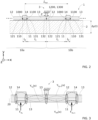
- FIG. 2 represents two elementary cells 10a and 10b adjacent to each other (or consecutive), where appropriate in said structure closed on itself, which are mechanically connected to the resonator 2 on its periphery deforming along the y axis (Cf. Figure 2 ) when the resonator is in operation.
- the diagram of the Figure 2 illustrates so-called operating nodes, sometimes noted below n u0 and n u1 , including at least two nodes of a first type n u1 comprising for example the points referenced 1000 and 1100, and nodes of a second type n u0 comprising for example the points referenced 1200 and 1300.
- the two operating nodes 1000 and 1100 must preferably be respectively located in the oval zones in bold dashes which are illustrated on the Figure 3 at the ends 111 and 112 of each primary bar 11 and at the ends of each tertiary bar 14, and in particular between the primary bar 11 concerned and the tertiary bar 14 concerned.
- each operating node 1200 should preferably be located within a bold dashed oval area which is illustrated in the Figure 3 between the secondary bar 12 of a first of the two elementary cells illustrated and the secondary bar 13 of the adjacent elementary cell, and in particular to the right of a second end 122 of the first secondary bar 12 of the left elementary cell and to the right of the frame 3.
- each operating node 1300 should preferably be located within a bold dashed oval area which is illustrated in the Figure 3 between the secondary bar 13 of a first of the two elementary cells illustrated and the secondary bar 12 of the adjacent elementary cell, and in particular at right angles to a second end 132 of the second secondary bar 13 of the cell 10a and at right angles to the frame 3.
- the operating nodes 1200 and 1300 are preferably spaced apart from each other by less than 30%, advantageously less than 10%, of the excitation wavelength of the resonator 2; they are preferably substantially coincident with each other. This preference is met when the secondary bars have the same length, are linked two by two by one of their ends, and that the secondary bars are mechanically linked to the frame 3 by the ends of the elementary cell to which they belong.
- these operating nodes 1000, 1100, 1200 and 1300 correspond to zones where the amplitude of deformation of the bars B u0, B u1 and B u2 is almost zero for a determined excitation frequency of the resonator 2 taken in a determined frequency band, typically taken in its useful band, for example between its resonance frequency and its antiresonance frequency.
- the primary 11 and secondary 12 and 13 bars of at least one elementary cell 10a can advantageously be dimensioned so that, for an excitation signal of the resonator 2 at the determined excitation frequency of the resonator 2, the operating nodes 1000, 1100, 1200 and 1300 are indeed found at the locations drawn on the Figure 2 or more generally in a respective area among the bold dashed oval areas illustrated on the Figure 3 , within 30%, advantageously 10%, of the excitation wavelength of resonator 2.
- Another way of expressing this desired technical effect consists of imposing, at these operating nodes 1000, 1100, 1200 and 1300, a movement of amplitude less than 10% of the maximum deformation amplitude generated in the secondary bars 12 and 13.
- the tertiary bar 14 of at least one elementary cell 10a preferably the tertiary bar 14 of each elementary cell 10a, 10b, 10c, etc. is preferably dimensioned in order to promote the propagation of mechanical waves coming from the secondary bars 12 and 13 towards the tertiary bars 14 rather than towards the primary bars 11.
- the primary bars 11 Since the aim is to limit as much as possible the energy transmitted by the resonator 2 to the frame 3 via the attachment 1, it is advantageous for the primary bars 11 to be sized so that they are put into resonance with the vibrating resonator 2 to guarantee the existence of the nodes 1000 and 1100 of the first type n u1 . To do this, the primary bars 11 should be sized so that they have a virtually zero mechanical impedance.
- the mechanical impedance Z can then be chosen such that at the working frequency and for the maximum displacement generated at the periphery of the resonator, the power supplied by the resonator to the support is less than 30% of the power lost internally via its mechanical losses.
- the resonance of the elements 11 makes it possible to minimize the transmission of mechanical energy from these elements to the elements 12 and therefore ultimately the energy extracted from the resonator 2 by the holding device 1 in its working environment 3.
- the second principle to be exploited consists of making the deformation waves induced at the levels of the consecutive mechanical connections, sometimes noted below a u and a u + 1 , between the elementary cells 10a and 10b and the resonator 2 interfere with each other.
- This function is carried out by the secondary bars 12 and 13, sometimes noted below B u1 .
- each of the first and second secondary bars 12 and 13 of at least one elementary cell 10a can be dimensioned so as to have a length substantially equal to a multiple of half a wavelength of the frequency, possibly average, of excitation of the resonator 2 and/or so as to have a quadratic moment, with respect to their longitudinal axis, at least four times greater, preferably at least ten times greater, than a quadratic moment of the primary bar 11 with respect to its longitudinal axis.
- transverse mechanical waves of amplitude ⁇ Y 0 are generated at the pulsation ⁇ in the material constituting the holding device 1 and therefore first in the bars B u 0 and B ( u +1)0 .
- the entire holding device 1 is intended to operate with a resonator 2 working over a well-defined frequency range, between its resonance frequency and its antiresonance frequency on a chosen mode; the interval including the deformation pulsation ⁇ is therefore known.
- a thickness of primary bar 11 will be chosen which is at least 10 times greater than the deformation amplitude, for example average, of the piezoelectric resonator in its excitation frequency band.
- the stiffness opposed by the primary bars 11 on the resonator 2 must therefore be low.
- reducing their quadratic moment I z makes it possible to reduce the opposing force and thus to minimize the energy transmitted to the binding 1 by the resonator 2.
- making the primary bars 11 enter into resonance at the excitation frequency of the resonator 2 makes it possible to reduce the equivalent stiffness of these bars 11 and therefore the energy transmitted to the rest of the binding 1. It is therefore interesting to develop primary bars 11 such that they resonate at the operating frequency of the resonator 2 and accompany its movement.
- the sizing of the primary bars 11 is therefore carried out so that they enter into resonance for a frequency located in the working frequency band of the resonator 2.
- the holding device 1 By the distribution, preferably substantially symmetrical, or even periodic, of the elementary cells 10a, 10b, 10c, etc. of the holding device 1, or even by the periodic structure that it forms, relative to the periphery of the resonator 2, the holding device 1 induces interference within it between the deformation waves produced at two consecutive connection points 110 at u and a (u + 1) with the resonator 2.
- the waves which enter at these connection points 110 consecutive at u and a (u+1) propagate on the primary bars 11, B u0 and B (u+1)0 , of two consecutive elementary cells, over a distance equivalent, in the propagation medium, to a quarter of the excitation wavelength of the resonator 2, forming quasi-nodes at the operating nodes 1000 and 1100 of the first type n u1 .
- the waves propagate on the secondary bars 12 and 13 to finally meet at the operating nodes 1200 and 1300 of the second type n u0 which are substantially merged with each other and located between two consecutive elementary cells 10a and 10b.
- An extended zero displacement node is defined here as an enlarged area (shown for the example, on the Figure 3 , by each of the oval areas in bold dashes) in which the displacement is substantially zero, typically, over a distance of ⁇ /10, where ⁇ is the possibly average wavelength of deformation.
- the displacement at an extended zero displacement node is preferably at least 10 times lower than the maximum displacement at the point of maximum displacement of the fixing 1. This makes it possible to be tolerant on the effective anchoring point to the frame 3, as well as on the working frequency induced by the vibration of the resonator 2. This is particularly necessary in the case of the use of a strongly coupled piezoelectric resonator 2 which can be made to operate over a wide frequency range (typically 20% of frequency variation).
- the extended zero displacement nodes are obtained at the interconnection points 1200 and 1300 of the second type n u0 , limiting the transmission of waves towards the frame 3 at these nodes 1200 and 1300. Due to the repetitive, even periodic, structure of the fixing 1, the effect produced at the operating nodes 1200 and 1300 which are located between the two consecutive elementary cells 10a and 10b partially illustrated on the Figure 2 , is also obtained on the operating nodes 1200 and 1300 which are located between two other consecutive elementary cells in the structure formed by the fixation 1. These operating nodes 1200 and 1300 of the second type n u0 can be noted below: n (u-1)0 , n (u+1)0 , etc.
- each secondary bar 12 and 13 of each elementary cell 10a, 10b, 10c, etc. obtains a stiffer relative stiffness on the working frequency (where the nature of the interference is of the destructive type, that is to say that, for a certain internal constraint, the relative displacement will be lower than for the case of the propagation of a single wave in particular on its periphery).
- the confinement of the wave during its transmission between the primary bar 11 and the secondary bars 12 and 13 of each elementary cell is increased.
- fixing 1 makes it possible to increase the relative stiffness of the secondary bars and produces nodes with zero displacement extended at the levels of the connections between fixing 1 and frame 3.
- the deformation waves emitted at the contact points 110 between the holding device 1 and the resonator 2 are substantially the same.
- the two waves will have traveled the same path, but in two opposite directions (x increasing or x decreasing on the Figure 2 ).
- the materials chosen for the secondary bars are substantially isotropic and that these bars are substantially of the same shape and dimensions, possibly with a symmetry of axis or plane near, the deformations produced by these two waves are then substantially equivalent in amplitude.
- connection point 110 (noted a u + 1 ), following a first connection point 110, noted a u , will continue to interfere with the wave emitted at the first connection point 110 (noted a u ) in the secondary bar 13 of the elementary cell 10a and, conversely, the wave emitted at the first connection point 110, noted a u , will interfere with the wave emitted from the second connection point a u + 1 in the secondary bar 12 of the second elementary cell 10b.
- the interference is of a destructive nature which tends to limit the amplitude of displacement of the secondary bars 12 and 13 and therefore contributes to minimizing losses which are functions of the quantity of material displaced.
- connection points a u and a u + 1 are located at distances such that the total distance L tot between two connection points is equal to or a multiple of half a wavelength that can be generated on the periphery of the resonator 2 in the working frequency band, a favored resonance can appear on the contours of the latter.
- 2 R corresponds to the main working characteristic length. As L tot is close to this length, we can assume that a favorable contour mode can be excited which is not desired. We will therefore prefer to work with four elementary cells and therefore four fixing points of resonator 2 on fixing 1.
- the primary bars 11 are sized to resonate at a frequency in the working frequency range of the resonator.
- the primary bars 11 are as if embedded-embedded substantially at the operating nodes 1000 and 1100 of the first type n u1 , and each attachment point a u of the resonator 2 to the attachment 1 is substantially located in the middle of the primary bar 11 which carries it.
- the resonance frequency of these primary bars 11 is chosen so that it corresponds to their main mode of resonance by considering each primary bar 11 in itself, i.e. not mechanically linked to the resonator 2.
- connection pad or lug 110 can be included, at least the mass of this pad, so that the “primary bar 11 + connection pad” assembly resonates well at the desired frequency.
- each primary bar 11 is chosen to be as flexible as possible within the limits of technical and economic possibilities, in order to further limit the energy transmitted to the fixing 1.
- the holding device 1 by producing the holding device 1 in a symmetrical, or even periodic, manner around the resonator 2, the deformation waves produced in the fixing 1 are put into destructive interference which makes it possible both to increase the equivalent stiffness of the secondary bars 12 and 13, but also to create connection nodes with zero displacements extended to the levels of the mechanical connections between consecutive elementary cells. It is these operating nodes 1200 and 1300 of the second type n u0 which are advantageously used to mechanically interface the fixing 1 with the frame 3.
- the tertiary bars 14 can be chosen to be large compared to the thickness of the primary bars 11.
- each tertiary bar 14 is matched in mechanical impedance with the secondary bars 12 and 13 so that most of the energy coming from the secondary bars is absorbed by the tertiary bars 14 and not by the primary bars 11.
- the stiffness of the secondary bars 12 and 13 is increased at the operating frequency by destructive interference, it will be sought to make the tertiary bars 14 stiffer than the primary bars 11.
- the primary bars 11 are preferably chosen to be thin compared to the thickness of the secondary bars 12 and 13, which accentuates the break in mechanical impedance and limits the energy exchanges between the primary bars 11 and the secondary bars 12 and 13, which is also advantageous.
- the proposed invention addresses the main problem of mechanically holding/maintaining a piezoelectric resonator 2 while limiting the impact of its holding device 1 for working modes of the longitudinal and/or transverse resonance type.
- the holding device 1 uses the interference of the waves propagating within it to minimize the energy transferred from the resonator to the frame 3 and to create extended nodes facilitating the connection of the holding device 1 to the frame 3, while limiting the transfer of energy to the frame 3. In doing so, the dimensions of the holding device 1 can be considerably reduced.
- the very principle of the holding device 1 described above can be adapted to several geometries (dimensions and shape) of resonators 2 and can be made of several different materials.
- the following section presents, as an example, calculation rules for the dimensioning of a holding device 1 adapted to a resonator 2 taking the form of a disc.
- a fixing device 1 which makes it possible to hold a piezoelectric resonator 2 of circular shape operating in a radial type vibration mode.
- a minimum of three attachment points 110 are necessary.
- the distance between the attachment points 110 on the periphery of the resonator 2 is then ⁇ 3 2 R , and, as ⁇ 3 is close to 1, we can easily assume that a diametrical mode will interfere in our operating band between the resonance frequency and the antiresonance frequency of the resonator 2.
- One solution is to add a fourth attachment point 110 which reduces the distance between the attachment points and allows the diametrical resonance mode to be isolated at a higher frequency far from the operating band. With four attachment points, the holding device 1 can be as illustrated in the Figure 4 .
- the first important parameters to consider are the working frequency band of the developed fixation 1 and also the dimension L tot available for the production of an elementary cell (or pattern) of the holding device 1. These two parameters are directly linked to the choice of the resonant piezoelectric material and to its dimensions.
- a material commonly used in electronics is FR-4 TG150. Its advantage is that it has good dielectric properties and can be purchased in copper-coated plates. This makes it possible to obtain two parallel conductive planes electrically insulated from each other which are useful for resuming electrical contacts between the piezoelectric resonator 2 and frame 3 through attachment 1.
- FR-4 TG150 has a Young's modulus E of 22GPa and a density ⁇ of 1900kg/m 3 .
- E Young's modulus
- ⁇ density
- the thickness of the copper is small compared to the height of the FR-4, only FR-4 will be considered for mechanical dimensioning.
- it is a composite material, it will be considered as isotropic for the dimensioning of the bars B u0 , B u1 and B u2 .
- only rectangular section bars will be considered, which are simpler to produce when machining an FR-4 plate with a milling cutter or a laser.
- the first set of bars to be sized corresponds to the set of primary bars, referenced 11 and noted B u0 .
- their length and their thickness will dimension the whole of the rest of the holding device 1.
- L tot which is equal to 22mm.
- the two secondary bars 12 and 13 of each elementary cell total a length of 17.7mm.
- the length l 1 of a single secondary bar B u1 is 8.85mm. In this way, the holding device 1 loops back on itself around resonator 2.
- the secondary bars 12 and 13 are connected on their periphery to the frame 3 at the operating nodes 1200 and 1300.
- the connection between the secondary bars 12 and 13 and the frame 3 is considered to be punctual.
- the bars are held on their second side via a bar considered to be very rigid substantially at a zero displacement node 1000 or 1100.
- the bars B u1 are considered to be embedded on the one hand and connected punctually on the other hand.
- the secondary bars B u1 have a thickness of 3.4 mm for an average radius of curvature of 14.5 mm relative to the center of the resonator 2. With these dimensions, extended zero displacement nodes are created at the points n u0 of attachment of the holding device 1 to the frame 3.
- the tertiary bars 14 denoted B u2
- the deformation waves propagating from the secondary bars B u1 to the tertiary bars B u2 and primary bars B u0 propagate mainly in the tertiary bars B u2 and little in the primary bars B u0 .
- the deformation waves are put into destructive interference which makes these bars very rigid at the frequency of study.
- the tertiary bars B u2 would also have to be rigid which would result in very thick bars.
- FIG. 4 represents the support sized using the above criteria.
- electrical connection tracks connecting the upper electrode of the resonator with the frame can be made in a simple way using conventional printed circuit board manufacturing processes often called PCBs (for Printed Circuit Boards in English).
- PCBs for Printed Circuit Boards in English.
- tracks connecting the lower electrode of the resonator with the frame can also be manufactured.
- the frame may be a continuation of the material used for the mounting, for example, in the case of using a PCB as described in this example, the PCB may continue to accommodate the resonator drive electronics and other electronic functions.
- connection points a u between the holding device 1 and the resonator 2 are directly electrical conductors (e.g. brass) and that have better mechanical properties.
- the only constraint for the placement of the connection points a u between the holding device 1 and the resonator 2 is that, at these points, the device maintenance 1 undergoes transverse deformations substantially in phase (within 30°) and of substantially the same amplitude (within 20%).
- the fixing device 1 may also be placed on the internal part of a resonator 2 in the form of a hollow disc or ring, and not necessarily along the outer perimeter thereof, as is the case in the example given above.
- the resonator 2 may have the form of a washer/tube and this washer/tube may be mechanically held by a holding device 1 according to the first aspect of the invention by its inner perimeter.
- the fixing device 1 in the case of using a piezoelectric resonator 2 for energy conversion, it is possible to produce the fixing device 1 directly in the material serving as support for the electronic circuit (ceramic, PCB).
- Another alternative consists of using the holding device 1 in matrix form for a multitude of resonators 2.
- the interference of the acoustic waves is no longer necessarily produced only by the mechanical connection points of a single resonator, but also by the mechanical connection points of other resonators 2, having for example substantially the same characteristics.
- the advantage of working in matrix format is to be able to work at high frequency, this being defined by the dimension of the resonator 25 while using a large surface area of resonators 2, which makes it possible to increase the power of a converter comprising the holding device 1 in matrix form.
- Figure 5 presents an implementation diagram of such a matrix structure.
- the holding device 1 was first designed for power electronics and the use of massive piezoelectric resonators 2. It forms an interesting assembly with the piezoelectric resonator component 2 and allows its use to be made more massive. As stated in the introduction, power converters are omnipresent and their frequency increase poses problems. If the solution of using piezoelectric resonators 2 proves to be truly relevant, the holding device according to the first aspect of the invention removes the problem of "how to implement these vibrating components" without disturbing their vibration and without transmitting vibrations to the frame 3.
- the holding device 1 according to the first aspect of the invention is entirely possible to use the holding device 1 according to the first aspect of the invention on radiofrequency systems, rather than on power converters. This would also make it possible to reduce their footprint. surface.
Landscapes
- Physics & Mathematics (AREA)
- Acoustics & Sound (AREA)
- Piezo-Electric Or Mechanical Vibrators, Or Delay Or Filter Circuits (AREA)
Applications Claiming Priority (1)
| Application Number | Priority Date | Filing Date | Title |
|---|---|---|---|
| FR2314768A FR3157735A1 (fr) | 2023-12-21 | 2023-12-21 | Dispositif de maintien pour résonateur piézoélectrique et convertisseur de puissance le comprenant |
Publications (1)
| Publication Number | Publication Date |
|---|---|
| EP4576573A1 true EP4576573A1 (de) | 2025-06-25 |
Family
ID=90904363
Family Applications (1)
| Application Number | Title | Priority Date | Filing Date |
|---|---|---|---|
| EP24222410.3A Pending EP4576573A1 (de) | 2023-12-21 | 2024-12-20 | Haltevorrichtung für piezoelektrischen resonator und stromwandler damit |
Country Status (3)
| Country | Link |
|---|---|
| US (1) | US20250226809A1 (de) |
| EP (1) | EP4576573A1 (de) |
| FR (1) | FR3157735A1 (de) |
Citations (6)
| Publication number | Priority date | Publication date | Assignee | Title |
|---|---|---|---|---|
| EP1041714A2 (de) | 1999-03-30 | 2000-10-04 | Murata Manufacturing Co., Ltd. | Tragstruktur für einen piezoelektrischen Resonator und piezoelektrischer Bauteil mit einer derartigen Struktur |
| US20100314969A1 (en) * | 2009-03-26 | 2010-12-16 | Sand9, Inc. | Mechanical resonating structures and methods |
| US8947176B2 (en) * | 2009-06-09 | 2015-02-03 | Commissariat à l'énergie atomique et aux énergies alternatives | Electromechanical resonator with resonant anchor |
| CN109546986A (zh) | 2018-11-29 | 2019-03-29 | 中国科学院半导体研究所 | 用于降低能量损耗的rf-mems谐振器支撑结构 |
| US10778182B2 (en) * | 2015-03-31 | 2020-09-15 | Murata Manufacturing Co., Ltd. | Resonator |
| CN107925395B (zh) * | 2015-09-21 | 2021-09-17 | 株式会社村田制作所 | 谐振子以及谐振装置 |
-
2023
- 2023-12-21 FR FR2314768A patent/FR3157735A1/fr active Pending
-
2024
- 2024-12-20 EP EP24222410.3A patent/EP4576573A1/de active Pending
- 2024-12-20 US US18/991,296 patent/US20250226809A1/en active Pending
Patent Citations (6)
| Publication number | Priority date | Publication date | Assignee | Title |
|---|---|---|---|---|
| EP1041714A2 (de) | 1999-03-30 | 2000-10-04 | Murata Manufacturing Co., Ltd. | Tragstruktur für einen piezoelektrischen Resonator und piezoelektrischer Bauteil mit einer derartigen Struktur |
| US20100314969A1 (en) * | 2009-03-26 | 2010-12-16 | Sand9, Inc. | Mechanical resonating structures and methods |
| US8947176B2 (en) * | 2009-06-09 | 2015-02-03 | Commissariat à l'énergie atomique et aux énergies alternatives | Electromechanical resonator with resonant anchor |
| US10778182B2 (en) * | 2015-03-31 | 2020-09-15 | Murata Manufacturing Co., Ltd. | Resonator |
| CN107925395B (zh) * | 2015-09-21 | 2021-09-17 | 株式会社村田制作所 | 谐振子以及谐振装置 |
| CN109546986A (zh) | 2018-11-29 | 2019-03-29 | 中国科学院半导体研究所 | 用于降低能量损耗的rf-mems谐振器支撑结构 |
Non-Patent Citations (1)
| Title |
|---|
| B.P. HARRINGTON ET AL.: "In-plane acoustic reflectors for reducing effective anchor loss in lateral-extensional MEMS resonators", J. MICROMECH. MICROENG., vol. 21, 2011, pages 085021 |
Also Published As
| Publication number | Publication date |
|---|---|
| US20250226809A1 (en) | 2025-07-10 |
| FR3157735A1 (fr) | 2025-06-27 |
Similar Documents
| Publication | Publication Date | Title |
|---|---|---|
| EP2441170B1 (de) | Electromechanischer resonator mit resonierender aufhängung | |
| EP1060562B1 (de) | Anordnung mit akustischen wellen geleitet in einer piezoelektrischen dünnschicht, geklebt auf einem trägersubstrat und verfahren zur herstellung | |
| EP2203976B1 (de) | Lambwellenresonator | |
| EP2909932B1 (de) | Wandler mit durch synchrone anregungsstrukturen geführten volumenwellen | |
| EP2130266B1 (de) | Antenne mit einem resonator mit einer filterungsbeschichtung und system mit einer solchen antenne | |
| WO2012049073A1 (fr) | Structure acoustique heterogene formee a partir d'un materiau homogene | |
| FR2923612A1 (fr) | Dispositif d'insonification comprenant un reseau tridimensionnel d'emetteurs disposes en spirale apte a generer un faisceau d'ondes focalisees de grande intensite | |
| FR2793499A1 (fr) | Structure dielectrique periodique du type a bande interdite photonique tridimensionnelle et son procede de fabrication | |
| CA2319690A1 (fr) | Filtre a resonateurs a ondes acoustiques de surface | |
| WO2001029964A1 (fr) | Filtre a ondes acoustiques d'interface notamment pour les liaisons sans fil | |
| FR2981204A1 (fr) | Resonateurs a ondes de volume sur structures verticales micro-usinees. | |
| EP0660981B1 (de) | Wandler für unidirektionale Weller | |
| FR3079101A1 (fr) | Structure de transducteur pour suppression de source dans les dispositifs de filtres a ondes acoustiques de surface | |
| FR3157735A1 (fr) | Dispositif de maintien pour résonateur piézoélectrique et convertisseur de puissance le comprenant | |
| EP2957031B1 (de) | Flache struktur eines mechanischen resonators welcher durch biege- und dehnungsschwingungen entkoppelt ist | |
| EP4079680B1 (de) | Vorrichtung zur elektromechanischen umwandlung und system, das eine solche vorrichtung verwendet | |
| EP1082812B1 (de) | Engspaltiger akustischer oberflächenwellenwandler | |
| EP2591549A1 (de) | Modul zur mechanischen abkopplung eines resonators mit hohem qualitätsfaktor | |
| EP2324516A1 (de) | Akustisches grenzflächenwellenelement | |
| FR2929774A1 (fr) | Dispositif de resonance micro-electromecanique a structure periodique. | |
| EP0451089B1 (de) | Hochfrequenter piezoelektrischer Schwinger | |
| WO2025141201A1 (fr) | Dispositif à ondes élastiques | |
| FR3131141A1 (fr) | Structure plane de resonateur mecanique a vibration d'extension-compression selon un mode partiel egal a trois |
Legal Events
| Date | Code | Title | Description |
|---|---|---|---|
| PUAI | Public reference made under article 153(3) epc to a published international application that has entered the european phase |
Free format text: ORIGINAL CODE: 0009012 |
|
| STAA | Information on the status of an ep patent application or granted ep patent |
Free format text: STATUS: REQUEST FOR EXAMINATION WAS MADE |
|
| 17P | Request for examination filed |
Effective date: 20241220 |
|
| AK | Designated contracting states |
Kind code of ref document: A1 Designated state(s): AL AT BE BG CH CY CZ DE DK EE ES FI FR GB GR HR HU IE IS IT LI LT LU LV MC ME MK MT NL NO PL PT RO RS SE SI SK SM TR |