EP4578533A2 - Unité d'échange de gaz - Google Patents
Unité d'échange de gaz Download PDFInfo
- Publication number
- EP4578533A2 EP4578533A2 EP25171750.0A EP25171750A EP4578533A2 EP 4578533 A2 EP4578533 A2 EP 4578533A2 EP 25171750 A EP25171750 A EP 25171750A EP 4578533 A2 EP4578533 A2 EP 4578533A2
- Authority
- EP
- European Patent Office
- Prior art keywords
- exchange unit
- gas exchange
- inlet
- venting device
- closing piston
- Prior art date
- Legal status (The legal status is an assumption and is not a legal conclusion. Google has not performed a legal analysis and makes no representation as to the accuracy of the status listed.)
- Pending
Links
Images






Classifications
-
- A—HUMAN NECESSITIES
- A61—MEDICAL OR VETERINARY SCIENCE; HYGIENE
- A61M—DEVICES FOR INTRODUCING MEDIA INTO, OR ONTO, THE BODY; DEVICES FOR TRANSDUCING BODY MEDIA OR FOR TAKING MEDIA FROM THE BODY; DEVICES FOR PRODUCING OR ENDING SLEEP OR STUPOR
- A61M1/00—Suction or pumping devices for medical purposes; Devices for carrying-off, for treatment of, or for carrying-over, body-liquids; Drainage systems
- A61M1/14—Dialysis systems; Artificial kidneys; Blood oxygenators ; Reciprocating systems for treatment of body fluids, e.g. single needle systems for hemofiltration or pheresis
- A61M1/16—Dialysis systems; Artificial kidneys; Blood oxygenators ; Reciprocating systems for treatment of body fluids, e.g. single needle systems for hemofiltration or pheresis with membranes
- A61M1/1698—Blood oxygenators with or without heat-exchangers
-
- B—PERFORMING OPERATIONS; TRANSPORTING
- B01—PHYSICAL OR CHEMICAL PROCESSES OR APPARATUS IN GENERAL
- B01D—SEPARATION
- B01D63/00—Apparatus in general for separation processes using semi-permeable membranes
- B01D63/02—Hollow fibre modules
- B01D63/026—Wafer type modules or flat-surface type modules
-
- A—HUMAN NECESSITIES
- A61—MEDICAL OR VETERINARY SCIENCE; HYGIENE
- A61M—DEVICES FOR INTRODUCING MEDIA INTO, OR ONTO, THE BODY; DEVICES FOR TRANSDUCING BODY MEDIA OR FOR TAKING MEDIA FROM THE BODY; DEVICES FOR PRODUCING OR ENDING SLEEP OR STUPOR
- A61M2206/00—Characteristics of a physical parameter; associated device therefor
- A61M2206/10—Flow characteristics
- A61M2206/12—Flow characteristics the flow being spirally in a plane, e.g. against a plane side of a membrane filter element
-
- A—HUMAN NECESSITIES
- A61—MEDICAL OR VETERINARY SCIENCE; HYGIENE
- A61M—DEVICES FOR INTRODUCING MEDIA INTO, OR ONTO, THE BODY; DEVICES FOR TRANSDUCING BODY MEDIA OR FOR TAKING MEDIA FROM THE BODY; DEVICES FOR PRODUCING OR ENDING SLEEP OR STUPOR
- A61M2206/00—Characteristics of a physical parameter; associated device therefor
- A61M2206/10—Flow characteristics
- A61M2206/20—Flow characteristics having means for promoting or enhancing the flow, actively or passively
-
- A—HUMAN NECESSITIES
- A61—MEDICAL OR VETERINARY SCIENCE; HYGIENE
- A61M—DEVICES FOR INTRODUCING MEDIA INTO, OR ONTO, THE BODY; DEVICES FOR TRANSDUCING BODY MEDIA OR FOR TAKING MEDIA FROM THE BODY; DEVICES FOR PRODUCING OR ENDING SLEEP OR STUPOR
- A61M2207/00—Methods of manufacture, assembly or production
-
- B—PERFORMING OPERATIONS; TRANSPORTING
- B01—PHYSICAL OR CHEMICAL PROCESSES OR APPARATUS IN GENERAL
- B01D—SEPARATION
- B01D2313/00—Details relating to membrane modules or apparatus
- B01D2313/08—Flow guidance means within the module or the apparatus
Definitions
- the invention relates to a gas exchange unit and a method for producing a gas exchange unit.
- lung function can be maintained using an artificial lung (oxygenator or gas exchange unit) until the lungs recover and natural lung function returns.
- oxygenator oxygenator or gas exchange unit
- blood is removed from the patient through an extracorporeal circuit and returned after treatment in the oxygenator.
- Conventional oxygenators for example, consist of stacked hollow fiber mats arranged at right angles to each other. The mats are embedded in four layers of potting compound at the edges using a centrifugal or spin-coating process, resulting in a square cross-sectional area through which the blood flows.
- conventional oxygenators use perforated distribution plates installed in the inlet and outlet areas of the oxygenator.
- Such an oxygenator is, for example, known from WO 2017/211460 A1 .
- the object of the present invention is to improve the flow guidance in an oxygenator so that the needs of medium to long-term lung support can be met in a simple manner.
- a gas exchange unit which comprises hollow fiber mats, wherein the gas exchange unit comprises an inlet which is eccentrically inclined.
- the gas exchange unit comprises an inlet which is eccentrically inclined.
- the hollow fiber mats have a circular cross-sectional area.
- the inlet of the gas exchange unit is arranged eccentrically to the fiber layers of the hollow fiber mats.
- the measures according to the invention create a gas exchange unit that eliminates the need for distribution plates and distributes the fluid flow (especially blood) evenly across the fiber surface formed from the hollow fiber mats using other means or measures.
- the gas exchange unit according to the invention has a longer application time or service life than known oxygenators. Furthermore, the probability of blood damage is low with the specified gas exchange unit.
- the gas exchange unit is also called an oxygenator.
- An oxygenator is a device that can enrich blood with oxygen and remove carbon dioxide from the blood. Thus, the oxygenator can replace or support the lungs both in the short term and over longer periods.
- the gas exchange unit provides for the inlet to be located at the front of a housing of the gas exchange unit.
- the arrangement of the inlet at the front of the gas exchange unit enables a homogeneous flow through the hollow fiber mats.
- the housing of the gas exchange unit has an inlet housing.
- the inlet is connected to the inlet housing, whose surface has structures. Suitable structures on the inner blood-carrying surface of the inlet housing also distribute the flow as evenly as possible.
- the inlet is inclined if the angle between a central axis of the inlet and a plane formed by the inlet housing is greater than 0° and/or less than 90°.
- the structures are arranged in a scoop-shaped, web-shaped, or cross-strut-like manner on the surface of the inlet housing.
- These scoop-shaped, web-shaped, or cross-strut-like structures allow for evenly distributed flow through or feeding the fiber surfaces in the gas exchange unit. The flow is uniform both in the inner and outer areas of the hollow fiber mats.
- the inlet is provided with a cross-sectional area that continuously widens in the flow direction, so that the flow velocity is reduced slowly and not abruptly.
- the ratio between diameter (dD) and length (dL) of the inlet of dD/2dL ⁇ 1 is advantageous. (In other words, the ratio between the radius of the inlet and the length of the flow is less than 1). This ratio changes over the barrel length. It can also change gradually in the inlet area.
- the diameter expansion of the inlet over the length of the inlet is less than 45°.
- the cross-sectional area of the inlet is designed to expand asymmetrically.
- the expansion can be asymmetrical to precisely direct the flow and thus distribute it evenly.
- the inlet has a cross-sectional area that is variable over the length of the inlet.
- the gas exchange unit is provided with an outlet whose cross-sectional area decreases in the direction of flow.
- the fluid, especially blood, is accelerated by a continuous decrease in cross-sectional area.
- a ratio between diameter expansion (dD) and run length (dL) of less than 1 is advantageous: dD/dL ⁇ 1 or dD/2dL.
- the venting device can be designed in such a way that it can be selectively transferred into a first operating state, in which a flushing of the venting device can be realized, or into a second operating state, in which a venting of a cavity of the gas exchange unit can be realized.
- two technical functions can thus advantageously be realized, namely venting from the cavity and flushing and thus cleaning the venting device.
- the venting device is flushed after a venting process. This can prevent any blood residues that may have flowed out during a venting process from remaining in the venting device.
- the The venting device can be switched either to the first operating state, in which the cavity of the gas exchange unit is not vented, or to the second operating state, in which the cavity of the gas exchange unit is vented.
- the venting device can only perform one technical function, namely venting the cavity.
- the gas exchange unit can have a vacuum source that can be fluidically connected to the venting device. By applying a vacuum in the venting device using the vacuum source, it is easy to ensure that the air in the cavity is removed from it.
- the gas exchange unit may have an adjusting element that serves to transfer the venting device to the first operating state or to the second operating state.
- the adjusting element may be configured differently depending on the application, as explained in more detail below.
- the venting device can have a closing piston, which is moved into a first position to implement the first operating state or into a second position to implement the second operating state.
- the closing piston can be mounted for linear movement and/or rotation so that it can be moved from the first position to the second position or vice versa.
- the closing piston can be mounted for rotation about its longitudinal axis.
- the closing piston can be designed such that one piston section is moved relative to another piston section to move the closing piston from the first position to the second position.
- the closing piston can have a fluid line that is not fluidically connected to the cavity in the first position of the closing piston and is fluidly connected to the cavity in the second position of the closing piston. Furthermore, the fluid line can be fluidly connected to a supply line for supplying a rinsing agent in the first position of the closing piston and not fluidly connected to the supply line in the second position of the closing piston. In the second position, the air in the cavity can be discharged from the cavity via the fluid line.
- the closing piston can be rotatably mounted and the adjusting element can be designed such that the closing piston is rotated when the adjusting element is actuated.
- the adjusting element can preferably be connected to the closing piston in a rotationally fixed manner.
- the sealing piston can have a weakened section designed such that in the second position the adjusting element passes through the sealing piston. In the first position of the sealing piston, the sealing piston can prevent air or blood from escaping from the cavity despite the weakened section.
- the adjusting element can be a pipette that has at least one opening in the section that passes through the sealing piston. The air in the cavity can be discharged from the cavity via the opening and the adjusting element.
- the weakening of the sealing piston can be achieved by a cut in the sealing piston.
- the inlet housing has stabilizers. These can be designed as webs or cross struts. During potting, where high temperatures and/or stresses can be reached, the inlet geometry remains intact and remains essentially unchanged by temperature changes.
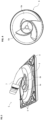
- Figure 3 shows the inlet housing 5 from Figure 2
- the eccentric, inclined arrangement of the inlet 7 is clearly visible.
- the structures 6, which distribute the flow homogeneously in the gas exchange unit 1, are designed as blade-shaped structures 6a and as web-shaped structures 6b.
- the structures 6 can also be arranged as cross struts on the surface of the inlet housing 5.
- the oblique transitions 9 result in a smooth, shock-free and thus blood-friendly transition even with different positions of the potting mirror.
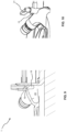
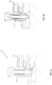
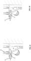
- Figure 15 shows an enlarged view of the Figure 12 shown venting device 15 and the adjusting element 21, wherein the venting device 15 is in the second operating state.
- the adjusting element 21 is rotated.
- FIG 23 shows an embodiment of an outlet housing 11.
- the outlet housing 11 has an outlet 12.
- the cross-sectional area of the outlet 12 decreases in the flow direction, as shown in the cross-sectional view of the outlet in Figure 22 is shown.
- the inlet housing 5, the outlet housing 11 and the housing part 3 form a housing of the gas exchange unit 1.
- the outlet housing 11 optionally has stabilizers 8, which can be designed as webs or cross struts. During potting, where high temperatures can be reached, the geometry of the outlet housing 11 is thus maintained and essentially remains unchanged by temperature changes.
- Figure 24 shows a cross-sectional view of the outlet 12.
- the cross-sectional area 10 of the outlet 12 narrows continuously in the direction of flow of the fluid (blood) in the area of the change in the main flow direction (deflection 13).
- the flow direction is indicated by an arrow.
- the narrowing can be asymmetrical.
- the cross-sectional area 10 can be variable along the length of the outlet 12.
- the fluid (blood) is accelerated by a continuous decrease in cross-sectional area on the outlet side of the gas exchange unit 1.
Landscapes
- Health & Medical Sciences (AREA)
- Emergency Medicine (AREA)
- Urology & Nephrology (AREA)
- Heart & Thoracic Surgery (AREA)
- Vascular Medicine (AREA)
- Engineering & Computer Science (AREA)
- Anesthesiology (AREA)
- Biomedical Technology (AREA)
- Hematology (AREA)
- Life Sciences & Earth Sciences (AREA)
- Animal Behavior & Ethology (AREA)
- General Health & Medical Sciences (AREA)
- Public Health (AREA)
- Veterinary Medicine (AREA)
- Chemical & Material Sciences (AREA)
- Chemical Kinetics & Catalysis (AREA)
- External Artificial Organs (AREA)
- Devices And Processes Conducted In The Presence Of Fluids And Solid Particles (AREA)
- Industrial Gases (AREA)
- Separation By Low-Temperature Treatments (AREA)
Applications Claiming Priority (4)
| Application Number | Priority Date | Filing Date | Title |
|---|---|---|---|
| DE102017008781 | 2017-09-20 | ||
| LU100759A LU100759B1 (de) | 2017-09-20 | 2018-03-29 | Gas-Austausch-Einheit |
| PCT/EP2018/075541 WO2019057858A1 (fr) | 2017-09-20 | 2018-09-20 | Unité d'échange gazeux |
| EP18785514.3A EP3684442B1 (fr) | 2017-09-20 | 2018-09-20 | Unité d'échange gazeux |
Related Parent Applications (1)
| Application Number | Title | Priority Date | Filing Date |
|---|---|---|---|
| EP18785514.3A Division EP3684442B1 (fr) | 2017-09-20 | 2018-09-20 | Unité d'échange gazeux |
Publications (2)
| Publication Number | Publication Date |
|---|---|
| EP4578533A2 true EP4578533A2 (fr) | 2025-07-02 |
| EP4578533A3 EP4578533A3 (fr) | 2025-10-15 |
Family
ID=63833959
Family Applications (2)
| Application Number | Title | Priority Date | Filing Date |
|---|---|---|---|
| EP25171750.0A Pending EP4578533A3 (fr) | 2017-09-20 | 2018-09-20 | Unité d'échange de gaz |
| EP18785514.3A Active EP3684442B1 (fr) | 2017-09-20 | 2018-09-20 | Unité d'échange gazeux |
Family Applications After (1)
| Application Number | Title | Priority Date | Filing Date |
|---|---|---|---|
| EP18785514.3A Active EP3684442B1 (fr) | 2017-09-20 | 2018-09-20 | Unité d'échange gazeux |
Country Status (7)
| Country | Link |
|---|---|
| US (1) | US12280192B2 (fr) |
| EP (2) | EP4578533A3 (fr) |
| JP (1) | JP7386154B2 (fr) |
| CN (1) | CN111148537B (fr) |
| ES (1) | ES3031943T3 (fr) |
| LU (1) | LU100759B1 (fr) |
| WO (1) | WO2019057858A1 (fr) |
Families Citing this family (2)
| Publication number | Priority date | Publication date | Assignee | Title |
|---|---|---|---|---|
| LU100759B1 (de) | 2017-09-20 | 2019-07-17 | Hemovent Gmbh | Gas-Austausch-Einheit |
| LU500436B1 (de) | 2021-07-15 | 2023-01-17 | Hemovent Gmbh | Vorrichtung und Verfahren zum Detektieren von Gasmengen an einem Oxygenator, mobiles Handgerät für einen Oxygenator, Oxygenator, Faser für eine Fasermatte für einen Oxygenator, Fasermatte eines Oxygenators, Fasermembran eines Oxygenators, Verfahren zum Herstellen von Fasern oder Fasermatten für einen Oxygenator, Verwendung einer Fasermatte für einen Oxygenator, Verwendung einer Faser für eine Fasermatte |
Citations (1)
| Publication number | Priority date | Publication date | Assignee | Title |
|---|---|---|---|---|
| WO2017211460A1 (fr) | 2016-06-10 | 2017-12-14 | Hemovent Gmbh | Unité d'échange gazeux, procédé de production d'une unité d'échange gazeux et ensemble comprenant une unité d'échange gazeux et un dispositif humidificateur et chauffant |
Family Cites Families (91)
| Publication number | Priority date | Publication date | Assignee | Title |
|---|---|---|---|---|
| US2659368A (en) | 1949-05-28 | 1953-11-17 | Jefferson Medical College Of P | Extracorporeal circulation device |
| US3639084A (en) | 1970-04-06 | 1972-02-01 | Baxter Laboratories Inc | Mechanism for control pulsatile fluid flow |
| US3838946A (en) | 1971-07-12 | 1974-10-01 | Dorr Oliver Inc | Air pressure-actuated double-acting diaphragm pump |
| US3842440A (en) | 1972-09-01 | 1974-10-22 | E Karlson | Implantable linear motor prosthetic heart and control system therefor |
| US3916449A (en) | 1972-12-06 | 1975-11-04 | Pacific Roller Die Co Inc | Implantable heart pump |
| GB1447394A (en) | 1972-12-06 | 1976-08-25 | Pacific Roller Die Co Inc | Heart pump |
| US3919722A (en) | 1973-03-06 | 1975-11-18 | Us Health | Totally implantable artificial replacement heart |
| US4094792A (en) | 1976-09-08 | 1978-06-13 | Bentley Laboratories, Inc. | Membrane fluid transfer method and apparatus |
| GB1595058A (en) | 1976-10-22 | 1981-08-05 | Bellhouse Brian John | Membrane blood oxygenators |
| US4116589A (en) | 1977-04-15 | 1978-09-26 | Avco Corporation | Extracorporeal pulsatile blood pump comprised of side by side bladders |
| DE2737920C2 (de) | 1977-08-23 | 1983-06-01 | Johannes Georg Dr.Dr. 3550 Marburg Schindler | Vorrichtung zum Gasaustausch zwischen einem strömenden Medium und einer äußeren Atmosphäre |
| WO1982003980A1 (fr) | 1981-05-19 | 1982-11-25 | Foxcroft Associates | Prothese cardiaque actionnee hydrauliquement |
| DE3342534C2 (de) | 1982-11-22 | 1986-03-20 | Helmut Ludwig 1000 Berlin Steiner | Elektromechanischer Blutpumpenantrieb |
| US4497104A (en) * | 1982-12-20 | 1985-02-05 | Baxter Travenol Laboratories, Inc. | Separation device manufacture |
| JPS61143075A (ja) | 1984-12-17 | 1986-06-30 | テルモ株式会社 | 膜型人工肺 |
| US4876066A (en) * | 1986-07-14 | 1989-10-24 | Baxter International Inc. | Integrated membrane oxygenator, heat exchanger and reservoir |
| US4854832A (en) | 1987-08-17 | 1989-08-08 | The Aro Corporation | Mechanical shift, pneumatic assist pilot valve for diaphragm pump |
| JPH01148266A (ja) * | 1987-12-04 | 1989-06-09 | Terumo Corp | 血液フィルター |
| JPH0614965B2 (ja) * | 1989-01-10 | 1994-03-02 | テルモ株式会社 | 人工肺 |
| US5116308A (en) * | 1989-01-13 | 1992-05-26 | Terumo Kabushiki Kaisha | Apparatus for processing fluid and method of driving the same |
| JPH0347270A (ja) | 1989-07-14 | 1991-02-28 | Terumo Corp | 流体処理装置 |
| CA2004295C (fr) | 1989-11-30 | 1998-02-10 | William F. Hayes | Pompe a liquide moteur et liquide propulse |
| JPH0526169A (ja) | 1990-10-05 | 1993-02-02 | Aisin Seiki Co Ltd | 流体送りポンピング装置 |
| US5232434A (en) | 1990-10-05 | 1993-08-03 | Aisin Seiki Kabushiki Kaisha | Fluid feeding pump unit |
| JPH04193178A (ja) | 1990-11-27 | 1992-07-13 | Mitsubishi Rayon Co Ltd | 中空糸膜型人工肺モジュール |
| US5230862A (en) * | 1991-08-16 | 1993-07-27 | Cardiopulmonics, Inc. | Apparatus for extracorporeal blood oxygenation |
| US5300111A (en) | 1992-02-03 | 1994-04-05 | Pyxis, Inc. | Total artificial heart |
| US5314469A (en) | 1992-03-11 | 1994-05-24 | Milwaukee Heart Research Foundation | Artificial heart |
| DE69401085T2 (de) * | 1993-04-22 | 1997-04-03 | Cobe Lab | Blutoxygenator mit Hohlfasern |
| US5514335A (en) | 1993-10-25 | 1996-05-07 | Minnesota Mining And Manufacturing Company | Blood oxygenation system and reservoir and method of manufacture |
| US6312647B1 (en) | 1994-12-09 | 2001-11-06 | Wayne State University | Method for enriching a fluid with oxygen |
| US5651765A (en) * | 1995-04-27 | 1997-07-29 | Avecor Cardiovascular Inc. | Blood filter with concentric pleats and method of use |
| DE19532365C2 (de) | 1995-09-01 | 1998-12-17 | Baxter Int | Hohlfaseroxygenator |
| US5751125A (en) | 1995-11-08 | 1998-05-12 | The Penn State Research Foundation | Artificial heart with sensorless motor |
| JPH09286920A (ja) | 1996-04-24 | 1997-11-04 | Fuji Syst Kk | シリコーンゴム中空糸及びその製造方法 |
| US20010003802A1 (en) | 1996-04-30 | 2001-06-14 | Vitale Nicholas G. | Magnetic spring and ventricle assist device employing same |
| US5965433A (en) | 1996-05-29 | 1999-10-12 | Trans D.A.T.A. Service, Inc. | Portable perfusion/oxygenation module having mechanically linked dual pumps and mechanically actuated flow control for pulsatile cycling of oxygenated perfusate |
| US5725763A (en) * | 1996-06-24 | 1998-03-10 | Millipore Corporation | Vacuum filtration device sealable vacuum vent |
| US6117390A (en) * | 1998-03-27 | 2000-09-12 | Medtronic, Inc. | Compact blood oxygenator utilizing longitudinally interspersed transversely extending heat exchanger conduits and oxygenator fibers |
| AU3743799A (en) | 1998-04-13 | 1999-11-01 | Edwards Lifesciences Corporation | Integrated modular oxygenator |
| US20020057989A1 (en) | 1998-05-15 | 2002-05-16 | Thomas A. Afzal | Integrated blood oxygenator and pump system having active blood oxygenator |
| US6454999B1 (en) | 1998-12-30 | 2002-09-24 | Cardiovention, Inc. | Integrated blood pump and oxygenator system having extended blood flow path |
| US6264601B1 (en) | 1999-04-02 | 2001-07-24 | World Heart Corporation | Implantable ventricular assist device |
| JP4258908B2 (ja) | 1999-09-14 | 2009-04-30 | 株式会社ジェイ・エム・エス | 人工肺装置 |
| ES2335680T3 (es) | 1999-09-30 | 2010-03-31 | Therox, Inc. | Sistema y metodo para oxigenar sangre. |
| US6998093B1 (en) | 2000-04-27 | 2006-02-14 | Medtronic, Inc. | Fluid oxygenator with access port |
| JP4077722B2 (ja) | 2000-10-12 | 2008-04-23 | リナル・ソリューションズ・インコーポレーテッド | 体外流体処理時における体液の流れを制御する装置及び方法 |
| US6730267B2 (en) * | 2001-02-09 | 2004-05-04 | Cardiovention, Inc. | Integrated blood handling system having active gas removal system and methods of use |
| US20020143397A1 (en) | 2001-04-02 | 2002-10-03 | Von Segesser Ludwig K. | Compliant artificial lung for extrapulmonary gas transfer |
| AU2003215342A1 (en) | 2002-02-21 | 2003-09-09 | Design Mentor, Inc. | Fluid pump |
| ITMI20021552A1 (it) | 2002-07-15 | 2004-01-15 | Dideco Spa | Dispositivo per il trattamento di sangue in circuito extracorporeo |
| JP2004154425A (ja) | 2002-11-07 | 2004-06-03 | Nemoto Kikaku Kogyo Kk | 人工心肺装置及び熱交換器 |
| WO2004043517A2 (fr) | 2002-11-07 | 2004-05-27 | Shigemasa, Osaki | Appareil de coeur-poumon artificiel |
| DE20307256U1 (de) | 2003-05-09 | 2003-10-02 | Lifebridge Medizintechnik GmbH, 85646 Neufarn | Tragbare Herzlungenmaschine |
| WO2005028002A1 (fr) | 2003-09-22 | 2005-03-31 | Dudu Haimovich | Systeme d'oxygenation du sang avec catheter a passage interne unique |
| CN1528472A (zh) | 2003-09-30 | 2004-09-15 | 韩国纽哈特生物有限公司 | 双搏动泵体外心肺生命支持系统 |
| DE102005039446B4 (de) | 2005-08-18 | 2009-06-25 | Ilias-Medical Gmbh | Vorrichtung zur An- und Abreicherung von Stoffen in einer Flüssigkeit |
| EP1968667A1 (fr) | 2005-12-29 | 2008-09-17 | Rikshospitalet- Radiumhospitalet HF | Procede et appareil pour l'estimation d'une valeur de pression arterielle en oxygene (pao2) pour un patient soumis a une circulation extracorporelle |
| US7981280B2 (en) | 2006-01-06 | 2011-07-19 | Renal Solutions, Inc. | Recirculation of blood in an extracorporeal blood treatment system |
| DE102007010112A1 (de) | 2007-02-28 | 2008-09-04 | Rheinisch-Westfälische Technische Hochschule Aachen | Vorrichtung für den Stoff- und/oder Energieaustausch |
| US8574291B2 (en) | 2007-08-17 | 2013-11-05 | Rheinisch-Westfaelische Technische Hochschule Aachen | Linear drive and pump system, in particular an artificial heart |
| US9795320B2 (en) | 2007-10-11 | 2017-10-24 | Peter Forsell | Device for treatment of aneurysm |
| SG153002A1 (en) * | 2007-11-16 | 2009-06-29 | Millipore Corp | Fluid transfer device |
| US8038640B2 (en) | 2007-11-26 | 2011-10-18 | Purity Solutions Llc | Diaphragm pump and related systems and methods |
| KR100985985B1 (ko) | 2008-03-07 | 2010-10-06 | 전북대학교산학협력단 | 박동형 심폐보조장치 |
| EP2113266A1 (fr) * | 2008-04-30 | 2009-11-04 | Gambro Lundia AB | Dispositif de dégazage |
| JP2010035869A (ja) | 2008-08-06 | 2010-02-18 | Jms Co Ltd | ドーム状血液導入部を有する膜型人工肺 |
| JP5347601B2 (ja) | 2009-03-16 | 2013-11-20 | 株式会社ジェイ・エム・エス | 血液処理装置 |
| DE102010004600A1 (de) | 2010-01-13 | 2011-07-14 | Marseille, Oliver, Dr.-Ing., 52066 | Anordnung mit einer Blutpumpe und einem Gasaustauscher zur extrakorporalen Membranoxygenierung |
| CN107335104A (zh) * | 2010-12-07 | 2017-11-10 | 措尔生命桥梁有限责任公司 | 使过滤器逐步注满的用于体外血液治疗的装置的填充和排气的方法及系统 |
| PL218244B1 (pl) | 2011-02-28 | 2014-10-31 | Fundacja Rozwoju Kardiochirurgii Im Prof Zbigniewa Religi | Pompa krwi, zwłaszcza implantowalna pneumatyczna komora wspomagania serca |
| JP5890827B2 (ja) | 2011-03-31 | 2016-03-22 | テルモ株式会社 | 人工肺 |
| MX344664B (es) | 2011-05-24 | 2017-01-04 | Deka Products Lp | Sistemas y metodos de tratamiento de la sangre. |
| DE102011052188A1 (de) | 2011-07-27 | 2013-01-31 | Maquet Vertrieb Und Service Deutschland Gmbh | Anordnung zum Erwärmen und/oder Befeuchten des Spülgases eines Oxygenerators |
| DE102011052189A1 (de) | 2011-07-27 | 2013-01-31 | Maquet Vertrieb Und Service Deutschland Gmbh | Elektronisch gesteuerte Gasmischeinheit zum Zuführen eines Spülgases zu einem Oxygenerator |
| DE102011054768A1 (de) | 2011-10-25 | 2013-04-25 | Stavros Kargakis | Künstliches Herz |
| EP2861272B1 (fr) | 2012-06-15 | 2017-08-09 | University of Pittsburgh - Of the Commonwealth System of Higher Education | Systèmes destinés à réduire la concentration de dioxyde de carbone dans le sang |
| JP2014151115A (ja) * | 2013-02-13 | 2014-08-25 | Jms Co Ltd | フィルタを内蔵した中空糸膜型人工肺 |
| JP2014183945A (ja) | 2013-03-22 | 2014-10-02 | Jms Co Ltd | フィルタを内蔵した中空糸膜型人工肺 |
| JP6538652B2 (ja) * | 2013-05-17 | 2019-07-03 | ノヴァラング ゲゼルシャフト ミット ベシュレンクテル ハフツング | 酸素供給器モジュール、酸素供給器、及び製造方法 |
| US10188780B2 (en) | 2013-12-23 | 2019-01-29 | University Of Maryland, Baltimore | Blood oxygenator |
| US10697447B2 (en) | 2014-08-21 | 2020-06-30 | Fenwal, Inc. | Magnet-based systems and methods for transferring fluid |
| EP3197516A2 (fr) | 2014-08-28 | 2017-08-02 | Ubaldo Lanucara | Dispositif permettant de générer des impulsions de pression bilatérales |
| US10589015B2 (en) | 2014-10-20 | 2020-03-17 | The Regents Of The University Of Michigan | Gated-concentric artificial lung |
| GB2533027B (en) | 2014-12-03 | 2020-06-03 | Spectrum Medical Ltd | Control system |
| FR3031310A1 (fr) | 2015-01-05 | 2016-07-08 | Gerard Plas | Prothese cardiaque integrale |
| EP3090768A1 (fr) * | 2015-05-07 | 2016-11-09 | Novalung GmbH | Dispositif doté de section d'admission destiné au traitement d'un liquide biologique |
| WO2018057892A1 (fr) * | 2016-09-22 | 2018-03-29 | Plott Christopher J | Dispositifs et procédés de conditionnement extracorporel du sang |
| BR102016022713A2 (pt) | 2016-09-29 | 2018-05-02 | Zammi Instrumental Ltda | Membrana para câmara de circulação de fluidos, câmara e bomba para assistência circulatória artificial e sistema de bombeamento |
| DE102017000843A1 (de) | 2017-01-31 | 2018-08-02 | Hemovent Gmbh | Extrakorporale Blutpumpe, Herz-Lungen-Maschine, Verfahren zum Betreiben einer extrakorporalen Blutpumpe sowie Verfahren zum Betreiben einer Herz-Lungen-Maschine |
| LU100759B1 (de) | 2017-09-20 | 2019-07-17 | Hemovent Gmbh | Gas-Austausch-Einheit |
-
2018
- 2018-03-29 LU LU100759A patent/LU100759B1/de active IP Right Grant
- 2018-09-20 US US16/647,930 patent/US12280192B2/en active Active
- 2018-09-20 ES ES18785514T patent/ES3031943T3/es active Active
- 2018-09-20 CN CN201880061107.3A patent/CN111148537B/zh active Active
- 2018-09-20 JP JP2020517171A patent/JP7386154B2/ja active Active
- 2018-09-20 EP EP25171750.0A patent/EP4578533A3/fr active Pending
- 2018-09-20 EP EP18785514.3A patent/EP3684442B1/fr active Active
- 2018-09-20 WO PCT/EP2018/075541 patent/WO2019057858A1/fr not_active Ceased
Patent Citations (1)
| Publication number | Priority date | Publication date | Assignee | Title |
|---|---|---|---|---|
| WO2017211460A1 (fr) | 2016-06-10 | 2017-12-14 | Hemovent Gmbh | Unité d'échange gazeux, procédé de production d'une unité d'échange gazeux et ensemble comprenant une unité d'échange gazeux et un dispositif humidificateur et chauffant |
Also Published As
| Publication number | Publication date |
|---|---|
| JP2020534113A (ja) | 2020-11-26 |
| EP3684442C0 (fr) | 2025-04-23 |
| US12280192B2 (en) | 2025-04-22 |
| CN111148537A (zh) | 2020-05-12 |
| EP3684442A1 (fr) | 2020-07-29 |
| EP4578533A3 (fr) | 2025-10-15 |
| JP7386154B2 (ja) | 2023-11-24 |
| LU100759A1 (de) | 2019-06-21 |
| CN111148537B (zh) | 2025-10-28 |
| ES3031943T3 (en) | 2025-07-14 |
| WO2019057858A1 (fr) | 2019-03-28 |
| US20200276375A1 (en) | 2020-09-03 |
| EP3684442B1 (fr) | 2025-04-23 |
| LU100759B1 (de) | 2019-07-17 |
Similar Documents
| Publication | Publication Date | Title |
|---|---|---|
| EP2996796B1 (fr) | Oxygénateur et son utilisation | |
| DE69515766T2 (de) | Dialysegerät | |
| EP3468637B1 (fr) | Unité d'échange gazeux et procédé de production d'une unité d'échange gazeux | |
| EP1218040B1 (fr) | Module a membranes pour hemodiafiltration avec predilution ou postdilution integree du sang | |
| DE2244594B2 (de) | Filter mit einem aus zwei Teilen bestehenden Gehäuse und darin befestigtem Filterelement | |
| WO2001060502A1 (fr) | Filtre a membranes en fibres creuses | |
| DE3026117C2 (de) | Peristaltische Pumpe | |
| EP3263154B1 (fr) | Dispositif de purge d'air et de vidange rapide d'un filtre | |
| EP2714249B1 (fr) | Dispositif d'échange de matière et/ou d'énergie entre deux fluides | |
| EP3684442B1 (fr) | Unité d'échange gazeux | |
| DE2138615A1 (de) | Dialysiergerat, insbesondere kunst liehe Niere und Verfahren zum Durchfuhren einer Dialyse mit einem solchen Gerat | |
| DE102009038673A1 (de) | Flechten der Hohlfaser bei Stoff-(Energie) Transportvorgängen in Austauscher-(Hohlfaser-)Modulen | |
| DE3435883A1 (de) | Dialysator | |
| DE102006020662B4 (de) | Verfahren zum Reparieren von Leckagen in einem Hohlfasermembranmodul | |
| DE102021133580B3 (de) | Verfahren und Vorrichtung zum Herstellen einer elektrischen Maschine sowie eine elektrische Maschine | |
| EP3268116B1 (fr) | Membrane destinée à un oxygénateur pour échange gazeux dans la circulation sanguine, oxygénateur pourvu d'une telle membrane et procédé de fabrication d'une telle membrane | |
| DE102022125964A1 (de) | Beschichtung von Hohlfasermembranen in der Medizintechnik III | |
| DE102007002486B4 (de) | Applikator für das chirurgische Wasserstrahltrennen zur Erzeugung eines Flachstrahls und Verfahren zur Herstellung des Applikators | |
| DE102015120572A1 (de) | Harzsperrvorrichtung für ein Infusionswerkzeug | |
| DE102022114273A1 (de) | Beschichtung von Hohlfasermembranen in der Medizintechnik | |
| DE102009033365A1 (de) | Rückschlagventil | |
| DE102024125325A1 (de) | Membran und Membrankontaktor | |
| DE102024115453A1 (de) | Gerinnselfänger mit Siebfläche und sich hiervon erhebender Struktur | |
| DE202005018532U1 (de) | Operationshandstück für eine Einrichtung zur Entnahme von Gewebezellen | |
| DE102024129926A1 (de) | Vorbereiten von Ports einer medizintechnischen Behandlungsvorrichtung für eine anstehende Behandlungssitzung |
Legal Events
| Date | Code | Title | Description |
|---|---|---|---|
| PUAI | Public reference made under article 153(3) epc to a published international application that has entered the european phase |
Free format text: ORIGINAL CODE: 0009012 |
|
| STAA | Information on the status of an ep patent application or granted ep patent |
Free format text: STATUS: THE APPLICATION HAS BEEN PUBLISHED |
|
| REG | Reference to a national code |
Ref country code: DE Ref legal event code: R079 Free format text: PREVIOUS MAIN CLASS: B01D0063020000 Ipc: A61M0001160000 |
|
| AC | Divisional application: reference to earlier application |
Ref document number: 3684442 Country of ref document: EP Kind code of ref document: P |
|
| AK | Designated contracting states |
Kind code of ref document: A2 Designated state(s): AL AT BE BG CH CY CZ DE DK EE ES FI FR GB GR HR HU IE IS IT LI LT LU LV MC MK MT NL NO PL PT RO RS SE SI SK SM TR |
|
| RIC1 | Information provided on ipc code assigned before grant |
Ipc: A61M 1/16 20060101AFI20250623BHEP Ipc: B01D 63/02 20060101ALI20250623BHEP |
|
| PUAL | Search report despatched |
Free format text: ORIGINAL CODE: 0009013 |
|
| AK | Designated contracting states |
Kind code of ref document: A3 Designated state(s): AL AT BE BG CH CY CZ DE DK EE ES FI FR GB GR HR HU IE IS IT LI LT LU LV MC MK MT NL NO PL PT RO RS SE SI SK SM TR |
|
| RIC1 | Information provided on ipc code assigned before grant |
Ipc: A61M 1/16 20060101AFI20250911BHEP Ipc: B01D 63/02 20060101ALI20250911BHEP |
|
| STAA | Information on the status of an ep patent application or granted ep patent |
Free format text: STATUS: REQUEST FOR EXAMINATION WAS MADE |