JP2005225719A - Dielectric ceramic composition - Google Patents
Dielectric ceramic composition Download PDFInfo
- Publication number
- JP2005225719A JP2005225719A JP2004036430A JP2004036430A JP2005225719A JP 2005225719 A JP2005225719 A JP 2005225719A JP 2004036430 A JP2004036430 A JP 2004036430A JP 2004036430 A JP2004036430 A JP 2004036430A JP 2005225719 A JP2005225719 A JP 2005225719A
- Authority
- JP
- Japan
- Prior art keywords
- subcomponent
- mol
- oxide
- dielectric
- main component
- Prior art date
- Legal status (The legal status is an assumption and is not a legal conclusion. Google has not performed a legal analysis and makes no representation as to the accuracy of the status listed.)
- Withdrawn
Links
- 239000000203 mixture Substances 0.000 title claims abstract description 71
- 239000000919 ceramic Substances 0.000 title claims abstract description 45
- 150000001875 compounds Chemical class 0.000 claims description 12
- 229910052791 calcium Inorganic materials 0.000 claims description 9
- 229910052712 strontium Inorganic materials 0.000 claims description 7
- 229910004298 SiO 2 Inorganic materials 0.000 claims description 6
- 229910052788 barium Inorganic materials 0.000 claims description 6
- 229910052749 magnesium Inorganic materials 0.000 claims description 6
- 229910052684 Cerium Inorganic materials 0.000 claims description 4
- 229910052692 Dysprosium Inorganic materials 0.000 claims description 4
- 229910052691 Erbium Inorganic materials 0.000 claims description 4
- 229910052693 Europium Inorganic materials 0.000 claims description 4
- 229910052688 Gadolinium Inorganic materials 0.000 claims description 4
- 229910052689 Holmium Inorganic materials 0.000 claims description 4
- 229910052765 Lutetium Inorganic materials 0.000 claims description 4
- 229910015868 MSiO Inorganic materials 0.000 claims description 4
- 229910052779 Neodymium Inorganic materials 0.000 claims description 4
- 229910052777 Praseodymium Inorganic materials 0.000 claims description 4
- 229910052772 Samarium Inorganic materials 0.000 claims description 4
- 229910052771 Terbium Inorganic materials 0.000 claims description 4
- 229910052775 Thulium Inorganic materials 0.000 claims description 4
- 229910052769 Ytterbium Inorganic materials 0.000 claims description 4
- 229910052746 lanthanum Inorganic materials 0.000 claims description 4
- 229910052750 molybdenum Inorganic materials 0.000 claims description 4
- 229910052758 niobium Inorganic materials 0.000 claims description 4
- 229910052706 scandium Inorganic materials 0.000 claims description 4
- 229910052715 tantalum Inorganic materials 0.000 claims description 4
- 229910052721 tungsten Inorganic materials 0.000 claims description 4
- 229910052720 vanadium Inorganic materials 0.000 claims description 4
- 229910052727 yttrium Inorganic materials 0.000 claims description 4
- 229910018068 Li 2 O Inorganic materials 0.000 claims description 2
- 229910052573 porcelain Inorganic materials 0.000 claims 1
- 239000000843 powder Substances 0.000 description 35
- 238000010304 firing Methods 0.000 description 30
- 239000002994 raw material Substances 0.000 description 26
- 239000000523 sample Substances 0.000 description 13
- 239000000758 substrate Substances 0.000 description 12
- 229910004762 CaSiO Inorganic materials 0.000 description 8
- 239000003989 dielectric material Substances 0.000 description 8
- 230000000694 effects Effects 0.000 description 8
- 239000000463 material Substances 0.000 description 8
- 238000010298 pulverizing process Methods 0.000 description 7
- 238000004891 communication Methods 0.000 description 6
- 239000011347 resin Substances 0.000 description 6
- 229920005989 resin Polymers 0.000 description 6
- 238000001354 calcination Methods 0.000 description 5
- 239000002131 composite material Substances 0.000 description 5
- 239000004372 Polyvinyl alcohol Substances 0.000 description 4
- 239000002184 metal Substances 0.000 description 4
- 229910052751 metal Inorganic materials 0.000 description 4
- 238000000034 method Methods 0.000 description 4
- 238000000465 moulding Methods 0.000 description 4
- 239000002245 particle Substances 0.000 description 4
- 229920002451 polyvinyl alcohol Polymers 0.000 description 4
- 238000005245 sintering Methods 0.000 description 4
- 239000011230 binding agent Substances 0.000 description 3
- 230000007423 decrease Effects 0.000 description 3
- 238000009413 insulation Methods 0.000 description 3
- 238000002156 mixing Methods 0.000 description 3
- 239000011368 organic material Substances 0.000 description 3
- 229910010413 TiO 2 Inorganic materials 0.000 description 2
- 230000008901 benefit Effects 0.000 description 2
- 239000003985 ceramic capacitor Substances 0.000 description 2
- 238000001035 drying Methods 0.000 description 2
- 238000011156 evaluation Methods 0.000 description 2
- 238000010438 heat treatment Methods 0.000 description 2
- 229910010272 inorganic material Inorganic materials 0.000 description 2
- 239000011147 inorganic material Substances 0.000 description 2
- 239000002002 slurry Substances 0.000 description 2
- BVKZGUZCCUSVTD-UHFFFAOYSA-L Carbonate Chemical compound [O-]C([O-])=O BVKZGUZCCUSVTD-UHFFFAOYSA-L 0.000 description 1
- YCKRFDGAMUMZLT-UHFFFAOYSA-N Fluorine atom Chemical compound [F] YCKRFDGAMUMZLT-UHFFFAOYSA-N 0.000 description 1
- 101100513612 Microdochium nivale MnCO gene Proteins 0.000 description 1
- 229910002651 NO3 Inorganic materials 0.000 description 1
- NHNBFGGVMKEFGY-UHFFFAOYSA-N Nitrate Chemical compound [O-][N+]([O-])=O NHNBFGGVMKEFGY-UHFFFAOYSA-N 0.000 description 1
- MUBZPKHOEPUJKR-UHFFFAOYSA-N Oxalic acid Chemical compound OC(=O)C(O)=O MUBZPKHOEPUJKR-UHFFFAOYSA-N 0.000 description 1
- 239000000654 additive Substances 0.000 description 1
- 230000000996 additive effect Effects 0.000 description 1
- 230000005540 biological transmission Effects 0.000 description 1
- 239000003990 capacitor Substances 0.000 description 1
- 230000001413 cellular effect Effects 0.000 description 1
- 230000008859 change Effects 0.000 description 1
- 238000006243 chemical reaction Methods 0.000 description 1
- 239000013078 crystal Substances 0.000 description 1
- 230000006866 deterioration Effects 0.000 description 1
- 238000011161 development Methods 0.000 description 1
- 239000002003 electrode paste Substances 0.000 description 1
- 230000001747 exhibiting effect Effects 0.000 description 1
- 229910052731 fluorine Inorganic materials 0.000 description 1
- 239000011737 fluorine Substances 0.000 description 1
- 239000008187 granular material Substances 0.000 description 1
- 238000000227 grinding Methods 0.000 description 1
- 238000005259 measurement Methods 0.000 description 1
- 238000010295 mobile communication Methods 0.000 description 1
- 239000004570 mortar (masonry) Substances 0.000 description 1
- 150000002902 organometallic compounds Chemical class 0.000 description 1
- 230000003647 oxidation Effects 0.000 description 1
- 238000007254 oxidation reaction Methods 0.000 description 1
- 230000008569 process Effects 0.000 description 1
- 230000009467 reduction Effects 0.000 description 1
- 239000007858 starting material Substances 0.000 description 1
- 229910052719 titanium Inorganic materials 0.000 description 1
- 230000007704 transition Effects 0.000 description 1
- XLYOFNOQVPJJNP-UHFFFAOYSA-N water Substances O XLYOFNOQVPJJNP-UHFFFAOYSA-N 0.000 description 1
- 239000013585 weight reducing agent Substances 0.000 description 1
Landscapes
- Control Of Motors That Do Not Use Commutators (AREA)
- Compositions Of Oxide Ceramics (AREA)
- Inorganic Insulating Materials (AREA)
Abstract
Description
本発明は、誘電体磁器組成物に関し、特にGHz帯といった高周波帯域において高い比誘電率、高いQfを有し、しかも比誘電率の温度特性が良好な誘電体磁器組成物に関するものである。 The present invention relates to a dielectric ceramic composition, and more particularly to a dielectric ceramic composition having a high relative dielectric constant and a high Qf in a high frequency band such as a GHz band and having a good temperature characteristic of the relative dielectric constant.
近年、通信機の小型化、軽量化、高速化が強く望まれている。その中で、デジタル携帯電話等の携帯移動体通信、衛星通信に使用される電波の周波数帯域はメガからギガHz帯(「GHz帯」という)の高周波帯域のものが使用されている。使用される通信機器の急速な発展の中で、匡体及び基板、電子素子の小型高密度実装化が図られているが、高周波帯域に対応した通信機器の小型化、軽量化をより一層推進するためには、通信機器に使用される基板等の材料はGHz帯において高周波伝送特性が優れた(誘電損失が小さい)ものでなければならない。ここで、誘電損失は周波数と基板の比誘電率εrと誘電正接(以下tanδと記載する)の積に比例する。よって、誘電損失を小さくするためには基板のtanδを小さくしなければならない。また、基板中では電磁波の波長が1/(εr)0.5に短縮されるため、比誘電率εrが大きい程基板の小型化が可能である。以上のことから高周波帯域で使用される小型の通信機器、電子機器、情報機器に用いる回路基板としては、比誘電率εrが高く、かつQf(品質係数Q=1/tanδ、f=共振周波数)が大きいことが要求されている。また、デバイスが使用される環境下、特に温度の変化に対して比誘電率εrの変動が小さいことが安定した特性を発揮するために重要である。 In recent years, miniaturization, weight reduction, and speeding up of communication devices have been strongly desired. Among them, the frequency band of radio waves used for portable mobile communications such as digital cellular phones and satellite communications is in the high frequency band of mega to giga Hz band (referred to as “GHz band”). Amid the rapid development of used communication equipment, the housing, board, and electronic elements have been miniaturized and densely mounted. However, the communication equipment that supports the high frequency band has been further reduced in size and weight. In order to achieve this, materials such as substrates used in communication equipment must be excellent in high-frequency transmission characteristics (low dielectric loss) in the GHz band. Here, the dielectric loss is proportional to the product of the frequency, the relative dielectric constant εr of the substrate, and the dielectric loss tangent (hereinafter referred to as tan δ). Therefore, in order to reduce the dielectric loss, tan δ of the substrate must be reduced. Further, since the wavelength of the electromagnetic wave in the substrate is shortened to 1 / (εr) 0.5 , the substrate can be downsized as the relative dielectric constant εr increases. As described above, a circuit board used for a small communication device, electronic device, or information device used in a high frequency band has a high relative dielectric constant εr and Qf (quality factor Q = 1 / tan δ, f = resonance frequency). Is required to be large. In addition, it is important for exhibiting stable characteristics that the variation of the relative dielectric constant εr is small with respect to a change in temperature in an environment where the device is used.
このような回路基板の材料としては、無機材料としての誘電体材料(焼結体)、有機材料としてフッ素樹脂等が用いられている。ところが、誘電体材料からなる基板は、寸法精度、加工性に難点があり、脆いため欠けや割れが生じやすいという問題点があった。他方、樹脂等の有機材料からなる基板は、成形性及び加工性に優れるという利点はあるが、比誘電率εrが小さいという問題があった。このため、近年、両者の利点を有する基板を得るため、例えば特許文献1(特許第2617639号公報)において有機材料と無機材料の複合体として樹脂材料中に誘電体材料からなる粉末を混合してなる複合基板が提案されている。 As a material for such a circuit board, a dielectric material (sintered body) as an inorganic material and a fluorine resin or the like as an organic material are used. However, a substrate made of a dielectric material has problems in dimensional accuracy and workability, and is fragile, so that there is a problem that chips and cracks are likely to occur. On the other hand, a substrate made of an organic material such as a resin has the advantage of being excellent in moldability and workability, but has a problem that the relative dielectric constant εr is small. Therefore, in recent years, in order to obtain a substrate having both advantages, for example, in Patent Document 1 (Japanese Patent No. 2617639), a powder made of a dielectric material is mixed in a resin material as a composite of an organic material and an inorganic material. A composite substrate is proposed.
一方で、誘電体材料の組成としては、例えば、特許文献2(特開2001−20229号公報)、特許文献3(特開2002−274938号公報)等、これまで種々のものが開発されている。特許文献2及び特許文献3は、積層型セラミックコンデンサを構成することを前提としている。そのため、特許文献2、3は、焼成時の耐還元性に優れ、焼成後には優れた容量温度特性を有し、しかも絶縁抵抗の加速寿命を向上させることができる誘電体磁器組成物を提供することを課題としている。しかるに、積層型セラミックコンデンサは、MHz帯での使用を前提としているため、特許文献2、3において、GHz帯域における比誘電率εr、Qf、比誘電率の温度特性τεrについて検討はなされていない。 On the other hand, various compositions have been developed as dielectric material compositions, such as Patent Document 2 (Japanese Patent Laid-Open No. 2001-20229) and Patent Document 3 (Japanese Patent Laid-Open No. 2002-294938). . Patent Document 2 and Patent Document 3 are premised on constituting a multilayer ceramic capacitor. Therefore, Patent Documents 2 and 3 provide dielectric ceramic compositions that are excellent in reduction resistance during firing, have excellent capacity-temperature characteristics after firing, and can improve the accelerated life of insulation resistance. It is an issue. However, since the multilayer ceramic capacitor is premised on use in the MHz band, Patent Documents 2 and 3 do not discuss the relative permittivity εr and Qf in the GHz band and the temperature characteristic τεr of the relative permittivity.
本発明は、以上の背景に基づいてなされたもので、GHz帯といった高周波帯域において高い比誘電率εr、高いQfを有し、しかも比誘電率の温度特性τεrが良好な誘電体磁器組成物を提供することを目的とする。 The present invention has been made on the basis of the above background. A dielectric ceramic composition having a high relative dielectric constant εr and a high Qf in a high frequency band such as a GHz band and a good temperature characteristic τεr of the relative dielectric constant. The purpose is to provide.
かかる目的のもと、本発明の誘電体磁器組成物は、(Sr1−xCax)mTiO3で示される組成の誘電体酸化物を含む主成分と、第1副成分としてCrの酸化物を含み、主成分に含まれる式中の組成モル比を示す記号x及びmが、0.32<x<0.42、0.965<m<1.035であり、主成分100モルに対して、第1副成分が、当該酸化物中のCr換算で、1モル未満(0を含まず)含有することを特徴としている。ここで、第1副成分は、高周波帯における比誘電率εr及び比抵抗ρを向上し、焼成温度を低下させる効果を有している。また、第1副成分としてのCrの酸化物の一部をMnの酸化物で置換することができる。 For this purpose, the dielectric ceramic composition of the present invention includes a main component containing a dielectric oxide having a composition represented by (Sr 1-x Ca x ) m TiO 3 and oxidation of Cr as a first subcomponent. Symbols x and m indicating the composition molar ratio in the formula included in the main component are 0.32 <x <0.42, 0.965 <m <1.035, and the main component is 100 mol. On the other hand, the first subcomponent is characterized by containing less than 1 mol (not including 0) in terms of Cr in the oxide. Here, the first subcomponent has the effect of improving the relative dielectric constant εr and the specific resistance ρ in the high frequency band and lowering the firing temperature. In addition, a part of the Cr oxide as the first subcomponent can be replaced with the Mn oxide.
本発明に係る誘電体磁器組成物は、さらに第2副成分として、X(ただし、XはV、Nb、W、Ta及びMoから選択される1種又は2種以上の元素)の酸化物を、主成分100モルに対して、当該酸化物中のX換算で、2モル未満(0を含まず)含有することが好ましい。この第2副成分は、焼成温度を低下させるとともに、高周波帯における比誘電率εr及びQfを向上させる効果を有している。 The dielectric ceramic composition according to the present invention further includes an oxide of X (where X is one or more elements selected from V, Nb, W, Ta and Mo) as the second subcomponent. It is preferable to contain less than 2 mol (excluding 0) in terms of X in the oxide with respect to 100 mol of the main component. This second subcomponent has the effect of lowering the firing temperature and improving the relative permittivity εr and Qf in the high frequency band.
本発明に係る誘電体磁器組成物は、さらに第3副成分として、R(ただし、RはSc、Y、La、Ce、Pr、Nd、Pm、Sm、Eu、Gd、Tb、Dy、Ho、Er、Tm、Yb及びLuから選択される1種又は2種以上の元素)の酸化物を、主成分100モルに対して、当該酸化物中のR換算で2モル未満(0を含まず)含有することが好ましい。この第3副成分は、高周波帯における比誘電率の温度特性τεrを向上させる効果を有している。 The dielectric ceramic composition according to the present invention further includes, as a third subcomponent, R (where R is Sc, Y, La, Ce, Pr, Nd, Pm, Sm, Eu, Gd, Tb, Dy, Ho, Less than 2 mol (excluding 0) in terms of R in the oxide with respect to 100 mol of the main component of oxide of Er, Tm, Yb and Lu) It is preferable to contain. This third subcomponent has the effect of improving the temperature characteristic τεr of the relative dielectric constant in the high frequency band.
また本発明に係る誘電体磁器組成物は、さらに第4副成分として、SiO2 、MO(ただし、MはBa、Ca、Sr及びMgから選択される1種又は2種以上の元素)、Li2 O、B2O3及びMSiO3から選択される1種又は2種以上の化合物を、主成分100モルに対して、当該酸化物換算で、5モル未満(0を含まず)含有することが好ましい。この第4副成分は、焼結助剤として焼成温度を低下させるとともに、高周波帯における比誘電率εr、Qfを向上させる効果を有している。 The dielectric ceramic composition according to the present invention further includes, as a fourth subcomponent, SiO 2 , MO (where M is one or more elements selected from Ba, Ca, Sr and Mg), Li 1 type or 2 or more types of compounds selected from 2 O, B 2 O 3 and MSiO 3 are contained in less than 5 mol (excluding 0) in terms of the oxide with respect to 100 mol of the main component. Is preferred. This fourth subcomponent has the effect of lowering the firing temperature as a sintering aid and improving the relative dielectric constants εr and Qf in the high frequency band.
以上の本発明による誘電体磁器組成物は、GHz帯でのTE011モードに由来する共振周波数fにおいて、比誘電率εr≧200、品質係数Q(=1/tanδ,tanδ:誘電正接)とfの積Qf≧4000(GHz)、−40〜85℃における比誘電率の温度特性τεrの絶対値|τεr|≦1000(ppm/℃)の特性を得ることができる。 The above dielectric ceramic composition according to the present invention has a relative dielectric constant εr ≧ 200, a quality factor Q (= 1 / tan δ, tan δ: dielectric loss tangent) and f at a resonance frequency f derived from the TE 011 mode in the GHz band. The characteristic of the absolute value | τεr | ≦ 1000 (ppm / ° C.) of the temperature characteristic τεr of the relative permittivity at −40 to 85 ° C. can be obtained.
以上説明したように、本発明によれば、第1副成分としてCrの酸化物を含み、かつ組成を最適化することにより、GHzを超える高い周波数帯域で高比誘電率、かつ高いQfが得られるとともに、比誘電率の温度特性τεrも良好な誘電体磁器組成物が得られる。 As described above, according to the present invention, by including the oxide of Cr as the first subcomponent and optimizing the composition, a high relative dielectric constant and a high Qf can be obtained in a high frequency band exceeding GHz. In addition, a dielectric ceramic composition having an excellent relative dielectric constant temperature characteristic τεr can be obtained.
以下本発明の誘電体磁器組成物をさらに詳細に説明する。
本発明の誘電体磁器組成物は、(Sr1−xCax)mTiO3で示される組成の誘電体酸化物を含む主成分と、第1副成分としてCrの酸化物を含み、主成分に含まれる式中の組成モル比を示す記号x及びmが、0.32<x<0.42、0.965<m<1.035であり、主成分100モルに対する第1副成分が、当該酸化物中のCr換算で、1モル未満(0を含まず)含有する。
Hereinafter, the dielectric ceramic composition of the present invention will be described in more detail.
The dielectric ceramic composition of the present invention includes a main component including a dielectric oxide having a composition represented by (Sr 1-x Ca x ) m TiO 3 and an oxide of Cr as a first subcomponent. The symbols x and m indicating the composition molar ratio in the formula contained in the formula are 0.32 <x <0.42 and 0.965 <m <1.035, and the first subcomponent with respect to 100 mol of the main component is Containing less than 1 mol (excluding 0) in terms of Cr in the oxide.
本発明の誘電体磁器組成物は、上記組成式において、xを、0.32<x<0.42とする。xはCa原子数を表し、xすなわちSr/Ca比を変えることで、結晶の相転移点を任意にシフトさせることが可能である。そのため比誘電率εr、Qf及び比誘電率の温度特性τεrを制御することができる。xが0.32以下になるとQfが4000GHzを超えることができないとともに、−40℃〜85℃における比誘電率の温度特性の絶対値|τεr|を1000ppm/℃以下にすることが困難となる。また、xが0.42以上になると比誘電率の温度特性τεrが悪化してその絶対値|τεr|を1000ppm/℃以下とすることができなくなる。xの範囲は、好ましくは0.34〜0.40、さらに好ましくは0.36〜0.38である。 In the dielectric ceramic composition of the present invention, in the above composition formula, x is 0.32 <x <0.42. x represents the number of Ca atoms, and the phase transition point of the crystal can be arbitrarily shifted by changing x, that is, the Sr / Ca ratio. Therefore, it is possible to control the relative permittivity εr, Qf and the temperature characteristic τεr of the relative permittivity. When x is 0.32 or less, Qf cannot exceed 4000 GHz, and it becomes difficult to make the absolute value | τεr | of the temperature characteristic of relative dielectric constant at −40 ° C. to 85 ° C. to 1000 ppm / ° C. or less. Further, when x is 0.42 or more, the temperature characteristic τεr of the relative permittivity deteriorates, and the absolute value | τεr | cannot be made 1000 ppm / ° C. or less. The range of x is preferably 0.34 to 0.40, more preferably 0.36 to 0.38.
本発明の誘電体磁器組成物は、上記組成式において、mを0.965<m<1.035とする。mが0.965以下になると4000GHz以上のQfを得ることができないとともに、比抵抗ρが大きく低下する。一方、mが1.035以上になると、焼成温度を高くしないと焼結が十分に進まないとともに、Qfが3000GHz未満の値にとどまるためである。mの範囲は、好ましくは0.970〜1.020、さらに好ましくは0.970〜1.010である。 In the dielectric ceramic composition of the present invention, m is 0.965 <m <1.035 in the above composition formula. When m is 0.965 or less, a Qf of 4000 GHz or more cannot be obtained, and the specific resistance ρ is greatly reduced. On the other hand, when m is 1.035 or more, sintering does not proceed sufficiently unless the firing temperature is increased, and Qf remains at a value of less than 3000 GHz. The range of m is preferably 0.970 to 1.020, more preferably 0.970 to 1.010.
本発明の誘電体磁器組成物は、第1副成分としてCrの酸化物を含有する。第1副成分の比率は、主成分100モルに対して、当該酸化物中のCr換算で1モル未満(0を含まず)とする。第1副成分の比率が1モル以上になると、Qf及び比抵抗ρが低下するからである。第1副成分の比率は、主成分100モルに対して、当該酸化物中のCr換算で好ましくは0.1〜0.8モル、さらに好ましくは0.1〜0.5モルである。 The dielectric ceramic composition of the present invention contains a Cr oxide as the first subcomponent. The ratio of the first subcomponent is less than 1 mol (excluding 0) in terms of Cr in the oxide with respect to 100 mol of the main component. This is because when the ratio of the first subcomponent is 1 mol or more, Qf and specific resistance ρ are reduced. The ratio of the first subcomponent is preferably 0.1 to 0.8 mol, more preferably 0.1 to 0.5 mol in terms of Cr in the oxide with respect to 100 mol of the main component.
本発明に係る誘電体磁器組成物は、さらに第2副成分として、X(ただし、XはV、Nb、W、Ta及びMoから選択される1種又は2種以上の元素)の酸化物を添加してあることが好ましい。この第2副成分の添加量は、主成分100モルに対して、当該酸化物中のX換算で2モル未満(0を含まず)の範囲とすることが好ましい。第2副成分の添加量が2モル以上になるとQfが低下するとともに、比抵抗ρも低下するからである。第2副成分の添加量は、主成分100モルに対して、当該酸化物中のX換算で、好ましくは0.1〜1.5モル、さらに好ましくは0.1〜1モルである。 The dielectric ceramic composition according to the present invention further includes an oxide of X (where X is one or more elements selected from V, Nb, W, Ta and Mo) as the second subcomponent. It is preferable to have added. The amount of the second subcomponent added is preferably less than 2 mol (excluding 0) in terms of X in the oxide with respect to 100 mol of the main component. This is because when the amount of the second subcomponent added is 2 mol or more, Qf decreases and the specific resistance ρ also decreases. The addition amount of the second subcomponent is preferably 0.1 to 1.5 mol, more preferably 0.1 to 1 mol, in terms of X in the oxide, with respect to 100 mol of the main component.
本発明に係る誘電体磁器組成物は、さらに第3副成分として、Rの酸化物(ただし、RはSc、Y、La、Ce、Pr、Nd、Pm、Sm、Eu、Gd、Tb、Dy、Ho、Er、Tm、Yb及びLuから選択される1種又は2種以上の元素)を添加してあることが好ましい。第3副成分の添加量は、主成分100モルに対して、当該酸化物中のR換算で、2モル未満(0を含まず)の範囲とする。第3副成分の添加量が2モル以上になると、Qf及び比抵抗ρが低下するとともに、比誘電率の温度特性τεrが悪化するからである。第3副成分の添加量は、主成分100モルに対して、当該酸化物中のR換算で、好ましくは0.01〜1.5モル、さらに好ましくは0.1〜1モルである。 The dielectric ceramic composition according to the present invention further includes, as a third subcomponent, an oxide of R (where R is Sc, Y, La, Ce, Pr, Nd, Pm, Sm, Eu, Gd, Tb, Dy). , Ho, Er, Tm, Yb and Lu are preferably added). The amount of the third subcomponent added is less than 2 mol (excluding 0) in terms of R in the oxide with respect to 100 mol of the main component. This is because when the amount of the third subcomponent added is 2 mol or more, Qf and the specific resistance ρ are lowered, and the temperature characteristic τεr of the dielectric constant is deteriorated. The addition amount of the third subcomponent is preferably 0.01 to 1.5 mol, more preferably 0.1 to 1 mol, in terms of R in the oxide, with respect to 100 mol of the main component.
本発明に係る誘電体磁器組成物では、さらに第4副成分として、SiO2 、MO(ただし、MはBa、Ca、Sr及びMgから選択される1種又は2種以上の元素)、Li2 O、B2 O3及びMSiO3から選択される1種又は2種以上の化合物を含むことが好ましい。この第4副成分は、主として焼結助剤として作用するが、Qfを向上する効果をも有している。
第4副成分の添加量は、主成分100モルに対して、当該酸化物換算で、5モル未満(0を含まず)とすることが好ましい。第4副成分の添加量が5モルを超えるとQfが低下するとともに、焼成温度を高くする必要がある。第4副成分の添加量は、主成分100モルに対して、好ましくは0.4〜3モル、さらに好ましくは1〜3モルである。
In the dielectric ceramic composition according to the present invention, SiO 2 , MO (where M is one or more elements selected from Ba, Ca, Sr, and Mg), Li 2 as a fourth subcomponent. It is preferable to include one or two or more compounds selected from O, B 2 O 3 and MSiO 3 . This fourth subcomponent mainly acts as a sintering aid, but also has an effect of improving Qf.
The addition amount of the fourth subcomponent is preferably less than 5 mol (excluding 0) in terms of the oxide with respect to 100 mol of the main component. When the added amount of the fourth subcomponent exceeds 5 mol, Qf is lowered and the firing temperature needs to be increased. The amount of the fourth subcomponent added is preferably 0.4 to 3 mol, more preferably 1 to 3 mol, per 100 mol of the main component.
本発明の誘電体磁器組成物の原料には、前述した本発明に係る誘電体磁器組成物の組成に応じ、主成分を構成する原料と、第1〜第4副成分を構成する原料とが用いられる。主成分を構成する原料としては、Sr、Ca、Tiの酸化物及び/又は焼成により酸化物になる化合物が用いられる。第1副成分を構成する原料としては、Crの酸化物及び/又は焼成により酸化物になる化合物が用いられる。第2副成分を構成する原料としては、X(ただし、XはV、Nb、W、Ta及びMoから選択される1種又は2種以上の元素)の酸化物及び/又は焼成により酸化物になる化合物から選択される1種類以上の単一酸化物又は複合酸化物が用いられる。第3副成分を構成する原料としては、R(ただし、RはSc、Y、La、Ce、Pr、Nd、Pm、Sm、Eu、Gd、Tb、Dy、Ho、Er、Tm、Yb及びLuから選択される1種又は2種以上の元素)の酸化物及び/又は焼成により酸化物になる化合物から選択される1種類以上の単一酸化物又は複合酸化物が用いられる。第4副成分を構成する原料としては、SiO2 、MO(ただし、MはBa、Ca、Sr及びMgから選択される1種又は2種以上の元素)、Li2 O、B2 O3及びMSiO3から選択される1種又は2種以上の化合物が用いられる。 According to the composition of the dielectric ceramic composition according to the present invention described above, the raw material of the dielectric ceramic composition of the present invention includes a raw material that constitutes the main component and a raw material that constitutes the first to fourth subcomponents. Used. As raw materials constituting the main component, oxides of Sr, Ca, Ti and / or compounds that become oxides upon firing are used. As a raw material constituting the first subcomponent, a Cr oxide and / or a compound that becomes an oxide by firing is used. As a raw material constituting the second subcomponent, an oxide of X (where X is one or more elements selected from V, Nb, W, Ta and Mo) and / or an oxide by firing One or more single oxides or complex oxides selected from the following compounds are used. As the raw material constituting the third subcomponent, R (wherein R is Sc, Y, La, Ce, Pr, Nd, Pm, Sm, Eu, Gd, Tb, Dy, Ho, Er, Tm, Yb, and Lu) 1 type or 2 or more types of elements selected from 1) and / or 1 type or more of single oxides or composite oxides selected from compounds that become oxides upon firing. As raw materials constituting the fourth subcomponent, SiO 2 , MO (where M is one or more elements selected from Ba, Ca, Sr and Mg), Li 2 O, B 2 O 3 and One or more compounds selected from MSiO 3 are used.
なお、焼成により酸化物になる化合物としては、例えば炭酸塩、硝酸塩、シュウ酸塩、有機金属化合物等が挙げられる。これらの化合物と酸化物とを併用してもよい。誘電体原料中の各化合物の含有量は、焼成後に前述した誘電体磁器組成物の組成となるように決定すればよい。これらの原料粉末の平均粒径は0.01〜5.0μm程度の範囲で適宜選択すればよい。 In addition, as a compound which becomes an oxide by baking, carbonate, nitrate, oxalate, an organometallic compound, etc. are mentioned, for example. These compounds and oxides may be used in combination. What is necessary is just to determine content of each compound in a dielectric material so that it may become the composition of the dielectric ceramic composition mentioned above after baking. What is necessary is just to select suitably the average particle diameter of these raw material powders in the range of about 0.01-5.0 micrometers.
これらの主成分及び副成分の原料粉末を、前述した本発明に係る誘電体磁器組成物の組成に応じて秤量し、例えばボールミルにより湿式混合する。このスラリーを乾燥後、例えば900〜1350℃の範囲で所定時間保持する仮焼を行う。このときの雰囲気はN2中又は大気中とすればよい。仮焼の保持時間は0.5〜5.0時間の範囲で適宜選択すればよい。仮焼後、仮焼体を例えば平均粒径0.5〜2.0μm程度まで粉砕する。その粉砕には例えばボールミル等が使用される。 These raw material powders of the main component and subcomponent are weighed according to the composition of the dielectric ceramic composition according to the present invention described above, and wet-mixed by, for example, a ball mill. After the slurry is dried, calcination is performed, for example, in the range of 900 to 1350 ° C. for a predetermined time. The atmosphere at this time may be in N 2 or air. What is necessary is just to select suitably the holding time of calcination in the range of 0.5 to 5.0 hours. After the calcination, the calcined body is pulverized, for example, to an average particle size of about 0.5 to 2.0 μm. For example, a ball mill is used for the pulverization.
なお、第1〜第4副成分の原料粉末を添加するタイミングは上述したものに限定されるものではない。例えば、まず主成分の原料粉末のみを秤量、混合、仮焼及び粉砕し、この仮焼粉砕後に得られた主成分の粉末に、第1〜第4副成分の原料粉末を所定量添加し、混合するようにしてもよい。 In addition, the timing which adds the raw material powder of a 1st-4th subcomponent is not limited to what was mentioned above. For example, first, only the main component raw material powder is weighed, mixed, calcined and pulverized, and the main component powder obtained after this calcined pulverization is added a predetermined amount of the first to fourth subcomponent raw material powders, You may make it mix.
前述の粉砕粉末は、後の成形工程を円滑に実行するために顆粒化される。この際、粉砕粉末に適当なバインダ、例えばポリビニルアルコール(PVA)を少量添加することが望ましい。得られる顆粒の粒径は80〜200μm程度とすることが望ましい。この造粒粉末を200〜300MPaの圧力で加圧成形し、所望の形状の成形体を得ることができる。 The aforementioned pulverized powder is granulated in order to smoothly execute the subsequent molding process. At this time, it is desirable to add a small amount of an appropriate binder such as polyvinyl alcohol (PVA) to the pulverized powder. The particle size of the obtained granules is preferably about 80 to 200 μm. The granulated powder can be pressure-molded at a pressure of 200 to 300 MPa to obtain a molded body having a desired shape.
成形時に添加したバインダを焼成前に加熱保持によって除去した後、例えば1250〜1500℃の範囲内で所定時間成形体を加熱保持し、焼結体を得る。このときの雰囲気はN2中又は大気中とすればよい。加熱時間は2〜6時間の範囲で適宜設定すればよい。本発明の誘電体磁器組成物の効果を充分に引き出すには、1300〜1400℃の範囲で焼成することが望ましい。 After removing the binder added during molding by heating and holding before firing, the molded body is heated and held for a predetermined time in a range of 1250 to 1500 ° C., for example, to obtain a sintered body. The atmosphere at this time may be in N 2 or air. What is necessary is just to set a heating time suitably in the range of 2 to 6 hours. In order to sufficiently bring out the effects of the dielectric ceramic composition of the present invention, it is desirable to fire in the range of 1300 to 1400 ° C.
以上の工程を経ることで、本発明における誘電体磁器組成物を得ることができる。本発明における誘電体磁器組成物は、GHz帯でのTE011モードに由来する共振周波数fにおける比誘電率εrが200以上、Qfが4000GHz以上、−40〜85℃における比誘電率の温度特性τεrの絶対値|τεr|が1000ppm/℃以下という特性を備える。こうした優れた特性を備える本発明による誘電体磁器組成物は、高周波用、特にマイクロ波の共振器、フィルタ、積層コンデンサ等の材料として好適である。 Through the above steps, the dielectric ceramic composition according to the present invention can be obtained. The dielectric ceramic composition of the present invention has a relative dielectric constant εr at a resonance frequency f derived from the TE 011 mode in the GHz band of 200 or more, a Qf of 4000 GHz or more, and a temperature characteristic τεr of the relative dielectric constant at −40 to 85 ° C. Has an absolute value | τεr | of 1000 ppm / ° C. or less. The dielectric ceramic composition according to the present invention having such excellent characteristics is suitable as a material for high frequency, particularly microwave resonators, filters, multilayer capacitors and the like.
また、本発明の誘電体磁器組成物は、前述した複合基板中に含有される誘電体粉末に適用することができる。この粉末は、原料粉末を焼成した後に粉砕して作製することができる。例えば、最終組成になるように秤量された原料粉末を混合した後に仮焼を行い、仮焼組成物に対して添加物を添加して粉砕し、さらに粉砕粉末を焼成し、得られた焼成物を粉砕することにより得ることができる。仮焼、焼成は、常法にしたがって行えばよい。また、粉砕についても同様である。なお、主成分及び第1〜第4副成分に関する原料粉末は、前述したように、酸化物粉末を用いることもできるし、焼成後に酸化物となる化合物粉末を用いることもできる。 The dielectric ceramic composition of the present invention can be applied to the dielectric powder contained in the composite substrate described above. This powder can be prepared by firing the raw material powder and then pulverizing it. For example, after calcining after mixing the raw material powders weighed to the final composition, adding the additive to the calcined composition and pulverizing it, further firing the pulverized powder, the resulting calcined product Can be obtained by grinding. The calcination and firing may be performed according to ordinary methods. The same applies to pulverization. In addition, as above-mentioned as raw material powder regarding a main component and a 1st-4th subcomponent, an oxide powder can also be used and the compound powder used as an oxide after baking can also be used.
複合基板を得る場合、誘電体粉末と樹脂との合計を100vol%としたとき、誘電体粉末の含有量は30〜70vol%とすることが好ましい。誘電体粉末の量が30vol%未満になる(樹脂の量が70vol%を超える)と、基板としての寸法安定性を欠くとともに、比誘電率εrが低下してしまう。つまり、誘電体粉末を含有する効果があまりみられない。一方、誘電体粉末の量が70vol%を超える(樹脂の量が30vol%未満になる)と、プレス成形の際、流動性が非常に悪くなり、緻密な成形物が得られなくなる。その結果、強度の低下、水等の侵入が容易になり電気特性の劣化につながる。また、誘電体セラミックス粉末を添加しない場合に比べて、Qfが大きく低下することもある。よって、誘電体粉末の含有量は30〜70vol%とする。望ましい誘電体粉末の含有量は30〜50vol%、さらに望ましい誘電体粉末の含有量は35〜50vol%である。 When obtaining a composite substrate, the content of the dielectric powder is preferably 30 to 70 vol% when the total of the dielectric powder and the resin is 100 vol%. When the amount of dielectric powder is less than 30 vol% (the amount of resin exceeds 70 vol%), the dimensional stability as a substrate is lacking and the relative dielectric constant εr is lowered. That is, the effect of containing dielectric powder is not so much seen. On the other hand, when the amount of the dielectric powder exceeds 70 vol% (the amount of the resin is less than 30 vol%), the fluidity becomes very poor during press molding, and a dense molded product cannot be obtained. As a result, the strength is reduced and water or the like can easily enter, leading to deterioration of electrical characteristics. Further, Qf may be greatly reduced as compared with the case where no dielectric ceramic powder is added. Therefore, the content of the dielectric powder is set to 30 to 70 vol%. The desirable dielectric powder content is 30-50 vol%, and the more desirable dielectric powder content is 35-50 vol%.
誘電体材料を作製するための出発原料として、それぞれ平均粒径0.1〜1μmの主成分原料としてのSrCO3、CaCO3、TiO2、及び第1〜第4副成分原料を用意した。副成分原料としては酸化物である第1副成分:Cr2O3、第2副成分:V2O5、第3副成分:Y2O3、第4副成分:CaSiO3をそれぞれ用いた。なお、第4副成分であるCaSiO3は、SiO2及びCaCO3をボールミルにより16時間湿式混合し、乾燥後、1330℃で空気中で焼成し、さらにボールミルで100時間湿式粉砕して得られたものを用いた。 As starting materials for producing the dielectric material, SrCO 3 , CaCO 3 , TiO 2 , and first to fourth subcomponent materials as main component materials each having an average particle diameter of 0.1 to 1 μm were prepared. As subcomponent materials, first subcomponent: Cr 2 O 3 , second subcomponent: V 2 O 5 , third subcomponent: Y 2 O 3 , and fourth subcomponent: CaSiO 3 which are oxides were used. . The fourth subcomponent CaSiO 3 was obtained by wet mixing SiO 2 and CaCO 3 with a ball mill for 16 hours, drying, firing in air at 1330 ° C., and further wet pulverizing with a ball mill for 100 hours. A thing was used.
これらの原料を組成式(Sr1−xCax)mTiO3(主成分)+Cr2O3(第1副成分)+V2O5(第2副成分)+Y2O3(第3副成分)+CaSiO3(第4副成分)において、焼成後に表1〜表6に示す組成になるように秤量した後、これらをそれぞれボールミルにより約16時間湿式混合した。このスラリーを充分乾燥した後、空気中、1230℃で仮焼成を行った。得られた仮焼成体を乳鉢で粗粉砕した後ボールミルにより約16時間湿式粉砕し、これを乾燥することによって誘電体磁器組成物(誘電体材料)を得た。なお、表1〜表6の第1〜第4副成分のモル数は、主成分100モルに対する比率である。 These raw materials are represented by the composition formula (Sr 1-x Ca x ) m TiO 3 (main component) + Cr 2 O 3 (first subcomponent) + V 2 O 5 (second subcomponent) + Y 2 O 3 (third subcomponent) ) + CaSiO 3 (fourth subcomponent) were weighed so as to have the compositions shown in Tables 1 to 6 after firing, and then wet mixed by a ball mill for about 16 hours. The slurry was sufficiently dried and then calcined at 1230 ° C. in the air. The obtained calcined body was roughly pulverized in a mortar, then wet pulverized by a ball mill for about 16 hours, and dried to obtain a dielectric ceramic composition (dielectric material). In addition, the number-of-moles of the 1st-4th subcomponent of Table 1-Table 6 is a ratio with respect to 100 mol of main components.
このようにして得られた乾燥後の誘電体材料にバインダとして適量のPVA(ポリビニルアルコール)を加えて造粒し、プレス成形により直径約12mm、厚さ約6mmのバルク成形体、及び直径約12mm、厚さ約1mmのディスク状成形体を作製した。これらの成形体を空気中、1300〜1400℃で焼成し、誘電体磁器組成物からなる試料を得た。バルク成形体については、焼成後、直径約10mm、厚さ約5mmに加工して、誘電体磁器組成物からなる試料を得た。 An appropriate amount of PVA (polyvinyl alcohol) as a binder is added to the dried dielectric material thus obtained and granulated, and a bulk molded body having a diameter of about 12 mm and a thickness of about 6 mm by press molding, and a diameter of about 12 mm. A disk-shaped molded body having a thickness of about 1 mm was produced. These molded bodies were fired in air at 1300 to 1400 ° C. to obtain a sample made of a dielectric ceramic composition. The bulk molded body was processed into a diameter of about 10 mm and a thickness of about 5 mm after firing to obtain a sample made of a dielectric ceramic composition.
得られた誘電体磁器組成物を用いて、誘電特性(比誘電率εr、Qf、比誘電率の温度特性τεr)及び比抵抗ρを測定した。
誘電特性の測定はHakki−Coleman法に基づき以下のように行った。
平行に配設された2枚の金属板にバルク試料を挟み、ネットワークアナライザー(ヒューレッドパッカード社製 8510C)に接続されたプローブを試料の両側に固定した。一方のプローブより高周波を発振して周波数特性を測定し、得られたTE011モードの共振ピークと試料寸法より比誘電率εrを求めた。また、標準試料を用いて前記金属板の表面比抵抗を求め、この値から金属板の誘電損失分を求めて全体の誘電損失値から前記金属板の誘電損失分を除き、試料のQfを得た。さらに、−40℃及び85℃における比誘電率εrを前述の方法と同様に求め、その温度間における比誘電率の温度特性τεrを算出した。その評価結果を表1〜表6に示す。
Using the obtained dielectric ceramic composition, dielectric characteristics (relative permittivity εr, Qf, temperature characteristic τεr of relative permittivity) and specific resistance ρ were measured.
The measurement of dielectric properties was performed as follows based on the Hakki-Coleman method.
A bulk sample was sandwiched between two metal plates arranged in parallel, and a probe connected to a network analyzer (8510C manufactured by Hured Packard) was fixed to both sides of the sample. A high frequency was oscillated from one probe and frequency characteristics were measured, and a relative dielectric constant εr was obtained from the obtained TE 011 mode resonance peak and sample size. Further, the surface resistivity of the metal plate is obtained using a standard sample, the dielectric loss of the metal plate is obtained from this value, and the dielectric loss of the metal plate is removed from the total dielectric loss value to obtain the Qf of the sample. It was. Further, the relative dielectric constant εr at −40 ° C. and 85 ° C. was obtained in the same manner as described above, and the temperature characteristic τεr of the relative dielectric constant between the temperatures was calculated. The evaluation results are shown in Tables 1 to 6.
比抵抗ρの測定は以下のようにして行った。
焼成後のディスク状試料の両面に電極ペーストを塗布した。この試料に絶縁抵抗計(アドバンテスト社製 R8340A)を用いて25℃でDC100Vを60秒間印加した後の絶縁抵抗IRを測定した。この測定値とディスク状試料の電極面積及び厚みとから、比抵抗ρ(Ωcm)を算出した。その評価結果を表1〜表6に示す。この表1〜表6において、比抵抗ρの欄の「aE+n」は「a×10+n」を意味する。
The specific resistance ρ was measured as follows.
An electrode paste was applied to both sides of the disc-shaped sample after firing. The insulation resistance IR after applying DC100V for 60 seconds at 25 degreeC was measured for this sample using the insulation resistance meter (Advantest R8340A). The specific resistance ρ (Ωcm) was calculated from this measured value and the electrode area and thickness of the disk-shaped sample. The evaluation results are shown in Tables 1 to 6. In Tables 1 to 6, “aE + n” in the column of specific resistance ρ means “a × 10 + n ”.
なお、これらの試料は、主成分原料であるSrCO3、CaCO3、TiO2を先に湿式混合し、仮焼した後に第1〜第4副成分を添加して湿式混合し、焼成する方法でも同様の特性が得られた。 In addition, these samples may also be a method in which SrCO 3 , CaCO 3 , and TiO 2 which are main component materials are first wet mixed, calcined, and then first to fourth subcomponents are added, wet mixed, and fired. Similar characteristics were obtained.
以上のようにして得られた試料は、原料やボールミルによる粉砕混合等から組成式に示した成分以外にZrO2、BaO等が混入するが、本発明の特性に影響を与えない範囲であれば混入していても差し支えない。 The sample obtained as described above contains ZrO 2 , BaO, etc. in addition to the components shown in the composition formula from raw materials and pulverized mixing with a ball mill, etc., as long as it does not affect the characteristics of the present invention. It can be mixed.
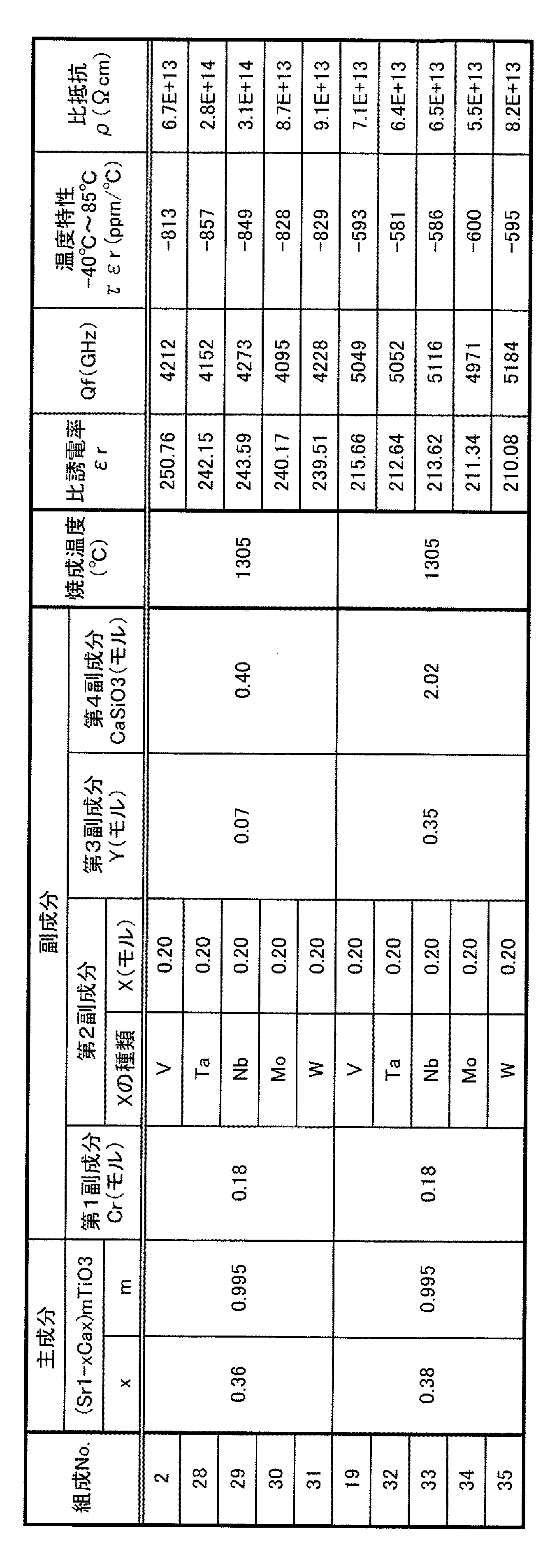
表1に示すように、Ca量を示すxが0.32ではQfが4000未満であるとともに、比誘電率の温度特性τεrも−1500ppm/℃程度である。また、xが0.42では比誘電率の温度特性τεrが−2000ppm/℃を下回ってしまう。以上の結果より、本発明ではxを0.32<x<0.42と規定した。好ましいxは0.34〜0.40、さらに好ましいxは0.36〜0.38である。 As shown in Table 1, when x indicating Ca content is 0.32, Qf is less than 4000, and the temperature characteristic τεr of relative dielectric constant is also about −1500 ppm / ° C. Further, when x is 0.42, the temperature characteristic τεr of the relative dielectric constant is less than −2000 ppm / ° C. From the above results, in the present invention, x is defined as 0.32 <x <0.42. Preferred x is 0.34 to 0.40, and more preferred x is 0.36 to 0.38.
表2に示すように、主成分のモル比(Sr+Ca)/Tiを表すmが0.965の場合にはQf及び比抵抗ρが低い。一方、mが1.035の場合には、焼成温度を1395℃と高くしないと焼結が十分に進まない。しかも、焼成温度を高くしてもQfが3000未満の値に低下する。したがって本発明では、mを0.965<m<1.035とする。好ましいmは0.970〜1.020、さらに好ましいmは0.970〜1.010である。 As shown in Table 2, when m representing the molar ratio (Sr + Ca) / Ti of the main component is 0.965, Qf and specific resistance ρ are low. On the other hand, when m is 1.035, sintering does not proceed sufficiently unless the firing temperature is increased to 1395 ° C. Moreover, even if the firing temperature is increased, Qf decreases to a value of less than 3000. Therefore, in the present invention, m is set to 0.965 <m <1.035. Preferred m is 0.970 to 1.020, and more preferred m is 0.970 to 1.010.
表3において、Cr2O3(第1副成分)を添加することにより、比誘電率εr及びQfが向上するとともに、比誘電率の温度特性τεrも向上することがわかる。ただし、その添加量が、酸化物中のCr換算で1.00モルになると、Qfの低下が顕著になるとともに、比抵抗ρの低下も無視できなくなる。したがって本発明では、第1副成分は酸化物中のCr換算で1モル未満(0を含まず)とする。第1副成分の添加量は、主成分100モルに対して、酸化物中のCr換算で、好ましくは0.1〜0.8モル、さらに好ましくは0.1〜0.5モルである。 In Table 3, it can be seen that the addition of Cr 2 O 3 (first subcomponent) improves the relative permittivity εr and Qf and also improves the temperature characteristic τεr of the relative permittivity. However, when the amount added is 1.00 mol in terms of Cr in the oxide, the Qf is significantly reduced and the specific resistance ρ is not negligible. Therefore, in the present invention, the first subcomponent is less than 1 mol (not including 0) in terms of Cr in the oxide. The addition amount of the first subcomponent is preferably 0.1 to 0.8 mol, more preferably 0.1 to 0.5 mol in terms of Cr in the oxide with respect to 100 mol of the main component.
表4に示すように、V2O5(第2副成分)を添加することにより、焼成温度が低下し、Qfが向上するとともに、比誘電率の温度特性τεrも向上する傾向にある。ただし、その添加量が、酸化物中のV換算で2.00モルになると、Qfの低下が顕著になるとともに、比抵抗ρの低下も無視できなくなる。したがって本発明では、第2副成分の添加量は酸化物中のV(X)換算で2モル未満(0を含まず)とする。第2副成分の添加量は、主成分100モルに対して、酸化物中のV(X)換算で、好ましくは0.1〜1.5モル、さらに好ましくは0.1〜1モルである。 As shown in Table 4, by adding V 2 O 5 (second subcomponent), the firing temperature is lowered, Qf is improved, and the temperature characteristic τεr of the dielectric constant tends to be improved. However, when the addition amount is 2.00 mol in terms of V in the oxide, the Qf is significantly reduced and the specific resistance ρ is not negligible. Therefore, in this invention, the addition amount of a 2nd subcomponent shall be less than 2 mol (0 is not included) in conversion of V (X) in an oxide. The addition amount of the second subcomponent is preferably 0.1 to 1.5 mol, more preferably 0.1 to 1 mol, in terms of V (X) in the oxide, relative to 100 mol of the main component. .
表5に示すように、Y2O3(第3副成分)を添加することにより、比誘電率の温度特性τεrが向上する。ただし、その添加量が、酸化物中のY換算で2.00モルになると、Qfの低下が顕著になるとともに、比誘電率の温度特性τεrの悪化も無視できなくなる。また、焼成温度が高くなる。したがって本発明では、第3副成分の添加量は、主成分100モルに対して、酸化物中のY(R)換算で2モル未満(0を含まず)とする。第3副成分の添加量は、主成分100モルに対して、酸化物中のY(R)換算で、好ましくは0.01〜1.5モル、さらに好ましくは0.1〜1モルである。 As shown in Table 5, the temperature characteristic τεr of the dielectric constant is improved by adding Y 2 O 3 (third subcomponent). However, when the added amount is 2.00 mol in terms of Y in the oxide, the Qf is significantly lowered and the temperature characteristic τεr of the dielectric constant cannot be ignored. In addition, the firing temperature is increased. Therefore, in the present invention, the amount of the third subcomponent added is less than 2 mol (excluding 0) in terms of Y (R) in the oxide with respect to 100 mol of the main component. The addition amount of the third subcomponent is preferably 0.01 to 1.5 mol, more preferably 0.1 to 1 mol, in terms of Y (R) in the oxide, relative to 100 mol of the main component. .
表6に示すように、CaSiO3(第4副成分)を添加することにより、Qfを向上させることができる。また、焼成温度の低下にもCaSiO3(第4副成分)の添加は有効である。ただし、その添加量が5.00モルになるとQfが低下するとともに、焼成温度を高くする必要がある。したがって、本発明ではCaSiO3(第4副成分)の量を5モル未満(0を含まず)とする。第4副成分の量は、主成分100モルに対して、好ましくは0.4〜3モル、さらに好ましくは1〜3モルである。 As shown in Table 6, Qf can be improved by adding CaSiO 3 (fourth subcomponent). Moreover, the addition of CaSiO 3 (fourth subcomponent) is also effective in reducing the firing temperature. However, when the added amount is 5.00 mol, Qf is lowered and the firing temperature needs to be increased. Therefore, in the present invention, the amount of CaSiO 3 (fourth subcomponent) is less than 5 mol (not including 0). The amount of the fourth subcomponent is preferably 0.4 to 3 mol, more preferably 1 to 3 mol, relative to 100 mol of the main component.
焼成後に表7に示す組成となるように原料粉末を秤量した以外は実施例1と同様に誘電体磁器組成物を作製し、やはり実施例1と同様にして比誘電率εr等の特性を測定した。その結果を表7に示す。なお、第1副成分の原料には、MnOの原料としてのMnCO3粉末及びCr2O3粉末を用いた。 A dielectric ceramic composition was prepared in the same manner as in Example 1 except that the raw material powder was weighed so as to have the composition shown in Table 7 after firing, and the characteristics such as the dielectric constant εr were measured in the same manner as in Example 1. did. The results are shown in Table 7. Note that the raw material of the first auxiliary component, with MnCO 3 powder and Cr 2 O 3 powder as a raw material of MnO.
表7に示すように、第1副成分としてのCr2O3の一部をMnOで置換した場合も、Cr2O3単独で添加した場合と同等の特性が得られることが確認できた。 As shown in Table 7, it was confirmed that even when a part of Cr 2 O 3 as the first subcomponent was substituted with MnO, the same characteristics as when Cr 2 O 3 was added alone were obtained.
焼成後に表8に示す組成となるように原料粉末を秤量した以外は実施例1と同様に誘電体磁器組成物を作製し、やはり実施例1と同様にして比誘電率εr等の特性を測定した。その結果を表8に示す。なお、第2副成分の原料には、各元素の酸化物粉末を用いた。 A dielectric ceramic composition was prepared in the same manner as in Example 1 except that the raw material powder was weighed so as to have the composition shown in Table 8 after firing, and the characteristics such as the dielectric constant εr were measured in the same manner as in Example 1. did. The results are shown in Table 8. In addition, the oxide powder of each element was used for the raw material of the 2nd subcomponent.
表8に示すように、V以外の第2副成分を用いても、Vを用いた場合と同等の特性が得られることが確認された。 As shown in Table 8, it was confirmed that even when the second subcomponent other than V was used, the same characteristics as when V was used were obtained.
焼成後に表9に示す組成となるように原料粉末を秤量した以外は実施例1と同様に誘電体磁器組成物を作製し、やはり実施例1と同様にして比誘電率εr等の特性を測定した。その結果を表8に示す。なお、第3副成分の原料には、各元素の酸化物粉末を用いた。 A dielectric ceramic composition was prepared in the same manner as in Example 1 except that the raw material powder was weighed so as to have the composition shown in Table 9 after firing, and the characteristics such as dielectric constant εr were measured in the same manner as in Example 1. did. The results are shown in Table 8. In addition, the oxide powder of each element was used for the raw material of the 3rd subcomponent.
表9に示すように、Y以外の第3副成分を用いた場合であっても、Yと同等の効果が得られることが確認された。 As shown in Table 9, it was confirmed that the same effect as Y was obtained even when the third subcomponent other than Y was used.
焼成後に表10に示す組成となるように原料粉末を秤量した以外は実施例1と同様に誘電体磁器組成物を作製し、やはり実施例1と同様にして比誘電率εr等の特性を測定した。その結果を表10に示す。なお、(Ba、Ca)SiO3、(Sr、Ca)SiO3および(Mg、Ca)SiO3は、SiO2およびMCO3(M=Ba、Sr、Ca、Mg)をボールミルにより16時間湿式混合し、乾燥後、1330℃で空気中で焼成し、さらにボールミルで100時間湿式粉砕して得られたものを用いた。 A dielectric ceramic composition was prepared in the same manner as in Example 1 except that the raw material powder was weighed so as to have the composition shown in Table 10 after firing, and the characteristics such as the dielectric constant εr were measured in the same manner as in Example 1. did. The results are shown in Table 10. (Ba, Ca) SiO 3 , (Sr, Ca) SiO 3 and (Mg, Ca) SiO 3 are wet-mixed for 16 hours with a ball mill using SiO 2 and MCO 3 (M = Ba, Sr, Ca, Mg). Then, after drying, the product obtained by firing in air at 1330 ° C. and wet pulverizing with a ball mill for 100 hours was used.
表10に示すように、CaSiO3以外の第4副成分を用いた場合にも、CaSiO3と同等の特性が得られることが確認された。 As shown in Table 10, it was confirmed that the same characteristics as CaSiO 3 were obtained even when the fourth subcomponent other than CaSiO 3 was used.
Claims (6)
前記主成分に含まれる式中の組成モル比を示す記号x及びmが、0.32<x<0.42、0.965<m<1.035であり、
前記主成分100モルに対して、前記第1副成分が、当該酸化物中のCr換算で、1モル未満(0を含まず)含有することを特徴とする誘電体磁器組成物。 A main component including a dielectric oxide having a composition represented by (Sr 1-x Ca x ) m TiO 3 and an oxide of Cr as a first subcomponent;
The symbols x and m indicating the composition molar ratio in the formula contained in the main component are 0.32 <x <0.42, 0.965 <m <1.035,
The dielectric ceramic composition, wherein the first subcomponent is contained in an amount of less than 1 mol (excluding 0) in terms of Cr in the oxide with respect to 100 mol of the main component.
Priority Applications (1)
| Application Number | Priority Date | Filing Date | Title |
|---|---|---|---|
| JP2004036430A JP2005225719A (en) | 2004-02-13 | 2004-02-13 | Dielectric ceramic composition |
Applications Claiming Priority (1)
| Application Number | Priority Date | Filing Date | Title |
|---|---|---|---|
| JP2004036430A JP2005225719A (en) | 2004-02-13 | 2004-02-13 | Dielectric ceramic composition |
Publications (1)
| Publication Number | Publication Date |
|---|---|
| JP2005225719A true JP2005225719A (en) | 2005-08-25 |
Family
ID=35000726
Family Applications (1)
| Application Number | Title | Priority Date | Filing Date |
|---|---|---|---|
| JP2004036430A Withdrawn JP2005225719A (en) | 2004-02-13 | 2004-02-13 | Dielectric ceramic composition |
Country Status (1)
| Country | Link |
|---|---|
| JP (1) | JP2005225719A (en) |
Cited By (2)
| Publication number | Priority date | Publication date | Assignee | Title |
|---|---|---|---|---|
| WO2012147769A1 (en) * | 2011-04-25 | 2012-11-01 | 京セラ株式会社 | Dielectric ceramic and dielectric filter provided with same |
| CN118530019A (en) * | 2024-05-24 | 2024-08-23 | 云南贵金属实验室有限公司 | A giant dielectric ceramic material based on strontium titanate with double donors co-doped at A and B positions and a preparation method thereof |
-
2004
- 2004-02-13 JP JP2004036430A patent/JP2005225719A/en not_active Withdrawn
Cited By (5)
| Publication number | Priority date | Publication date | Assignee | Title |
|---|---|---|---|---|
| WO2012147769A1 (en) * | 2011-04-25 | 2012-11-01 | 京セラ株式会社 | Dielectric ceramic and dielectric filter provided with same |
| CN103492346A (en) * | 2011-04-25 | 2014-01-01 | 京瓷株式会社 | Dielectric ceramic and dielectric filter provided with same |
| CN103492346B (en) * | 2011-04-25 | 2015-05-27 | 京瓷株式会社 | Dielectric ceramic and dielectric filter provided with same |
| JP5774094B2 (en) * | 2011-04-25 | 2015-09-02 | 京セラ株式会社 | Dielectric ceramics and dielectric filter provided with the same |
| CN118530019A (en) * | 2024-05-24 | 2024-08-23 | 云南贵金属实验室有限公司 | A giant dielectric ceramic material based on strontium titanate with double donors co-doped at A and B positions and a preparation method thereof |
Similar Documents
| Publication | Publication Date | Title |
|---|---|---|
| US20110245066A1 (en) | Dielectric ceramic, method for producing dielectric ceramic, and method for producing powder for producing dielectric ceramic | |
| TWI331136B (en) | ||
| JP4596004B2 (en) | High frequency dielectric ceramic composition, dielectric resonator, dielectric filter, dielectric duplexer, and communication device | |
| KR101607582B1 (en) | Dielectric ceramic composition. dielectric ceramic, electronic component, and communication device | |
| CN100519472C (en) | Dielectric porcelain composition and method for production thereof | |
| JP2005225735A (en) | Production method for dielectric porcelain composition | |
| JP2005225719A (en) | Dielectric ceramic composition | |
| JP7315902B2 (en) | Dielectric porcelain composition and electronic parts | |
| JP6179544B2 (en) | Dielectric porcelain composition, electronic component and communication device | |
| JP2003146752A (en) | Dielectric porcelain composition | |
| JP5247561B2 (en) | Dielectric ceramics and dielectric resonator | |
| JP2005225720A (en) | Dielectric ceramic composition | |
| JP4465663B2 (en) | Dielectric porcelain composition | |
| JP3940419B2 (en) | Dielectric ceramic composition and manufacturing method thereof | |
| KR100823217B1 (en) | Dielectric ceramic composition and manufacturing method thereof | |
| JP4541692B2 (en) | Dielectric porcelain composition | |
| JP4494756B2 (en) | Dielectric ceramic composition and dielectric resonator using the same | |
| JP2009227483A (en) | Dielectric ceramic composition | |
| JP2006124270A (en) | Dielectric porcelain composition and method for production thereof | |
| JP2005170732A (en) | Dielectric porcelain composition | |
| JP2007045690A (en) | Dielectric porcelain composition | |
| JP4383951B2 (en) | High frequency dielectric ceramic composition and method for producing the same | |
| JP2005179110A (en) | Dielectric ceramic composition | |
| JP2007063076A (en) | Dielectric ceramic composition | |
| KR100308915B1 (en) | High Frequency Dielectric Magnetic Composition |
Legal Events
| Date | Code | Title | Description |
|---|---|---|---|
| A300 | Withdrawal of application because of no request for examination |
Free format text: JAPANESE INTERMEDIATE CODE: A300 Effective date: 20070501 |