JP2005295967A - Transplanter - Google Patents

Transplanter Download PDF

Info

Publication number
JP2005295967A
JP2005295967A JP2004121189A JP2004121189A JP2005295967A JP 2005295967 A JP2005295967 A JP 2005295967A JP 2004121189 A JP2004121189 A JP 2004121189A JP 2004121189 A JP2004121189 A JP 2004121189A JP 2005295967 A JP2005295967 A JP 2005295967A
Authority
JP
Japan
Prior art keywords
seedling
seedlings
planting
transplanting
claw
Prior art date
Legal status (The legal status is an assumption and is not a legal conclusion. Google has not performed a legal analysis and makes no representation as to the accuracy of the status listed.)
Pending
Application number
JP2004121189A
Other languages
Japanese (ja)
Inventor
Tomohiro Takeyama
智洋 竹山
Current Assignee (The listed assignees may be inaccurate. Google has not performed a legal analysis and makes no representation or warranty as to the accuracy of the list.)
Yanmar Co Ltd
Original Assignee
Yanmar Co Ltd
Priority date (The priority date is an assumption and is not a legal conclusion. Google has not performed a legal analysis and makes no representation as to the accuracy of the date listed.)
Filing date
Publication date
Application filed by Yanmar Co Ltd filed Critical Yanmar Co Ltd
Priority to JP2004121189A priority Critical patent/JP2005295967A/en
Publication of JP2005295967A publication Critical patent/JP2005295967A/en
Pending legal-status Critical Current

Links

Images

Landscapes

  • Transplanting Machines (AREA)

Abstract

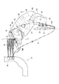
<P>PROBLEM TO BE SOLVED: To enable a single seedling-transplanting tine to easily carry out a series of operations from the taking out of seedlings to the transplantation of the seedlings, and to enable the seedlings taken out from a seedling-carrying platform by a seedling-transplanting tine to be transplanted in good accuracy. <P>SOLUTION: The subject transplanter has the seedling-transplanting tines 16 for taking out the cell-shaped seedlings N stored in a seedling tray 15 put on the seedling-carrying platform 14, and transplanting the taken out seedlings N, and a seedling-pushing out member 72 for pushing out the seedlings from the transplanting tine when transplanting the seedlings. The first rotary member 17 rotating by using a center rotary shaft in the right and left direction as the center, and the second rotary members 18 having the base terminals connected to output shafts 39 at both terminals of the first rotary member 17 are installed. The seedling-transplanting tines 16 are attached to the output shafts 49 at the tips of the second rotary members 18 so that the fulcrum parts of the seedling-transplanting tines 16 may be moved so as to draw nearly triangle loci K, and the tips of the seedling-transplanting tines 16 may be swung by centering the fulcrum parts to move the tips of the seedling-transplanting tines 16 so as to draw the seedling-transplanting loci A. <P>COPYRIGHT: (C)2006,JPO&NCIPI

Description

本発明は、苗トレイから苗植付爪によって取出した1株分の玉ネギ、葉ネギ、白ネギなどの苗をそのまま直接的に圃場に植え付けるようにした移植機に関する。   The present invention relates to a transplanter in which seedlings such as onions, leaf onions, and white onions taken out from a seedling tray by seedling planting nails are directly planted in a field.

従来、苗載台の苗トレイから1つの苗取出爪によって取出した苗を1つの苗植付爪に受継いで1条分の苗植付けを行う苗取出爪と苗植付爪とによる受継方式の移植機がある(例えば、特許文献1参照。)。   Conventionally, a seedling removal nail and a seedling planting nail that transfer seedlings from one seedling tray of a seedling stand with one seedling extraction nail to one seedling planting nail and plant one seedling There is a transplanter (for example, refer to Patent Document 1).

特開2001−211713号公報Japanese Patent Laid-Open No. 2001-211713

しかし、上述のような受継方式の場合、苗取出爪と苗植付爪それぞれの駆動を必要とするばかりでなく、同期させる必要があるため構造が極めて複雑化すると共に、苗取出爪より苗植付爪に苗受継時には苗姿勢に乱れを起生させ、特に高速となる程乱れを顕著なものとさせて、苗植付精度を低下させるなどの不都合があった。また、単一の苗植付爪で苗の取出しから苗の植付けまでの一連の植付作業を行う技術もあり、該技術の場合には、苗植付爪が土中に突入したときに苗を確実に押出して苗の持上げを防止すると共に、苗植付爪に土が付着した場合にも次回苗取出しに悪影響を与えないようにこの土を強制除去するために、苗押出部材を苗植付爪に沿って上下動自在に設け、苗植付爪に挟持した苗を押出すようにしているが、苗押出部材の移動方向と植付爪に挟持した苗の向きとが略同じであるため、苗植付時に苗押出部材により苗が曲げられて植付姿勢不良となることがあった。   However, in the case of the transfer method as described above, not only the driving of the seedling picking nails and the seedling planting nails are required, but also the structure is extremely complicated because it is necessary to synchronize them. When the seedlings are handed over to the nail, there is a problem in that the seedling posture is disturbed, and the disturbance becomes particularly noticeable as the speed increases, thereby reducing the seedling placement accuracy. In addition, there is a technique for performing a series of planting operations from taking out seedlings to planting seedlings with a single seedling planting nail. In this technique, when the seedling planting nail enters the soil, In order to prevent the raising of the seedling by extruding the seedling reliably, and to forcibly remove this soil so as not to adversely affect the next seedling removal even if soil adheres to the seedling planting nails, It is provided so that it can be moved up and down along the nail, and the seedling sandwiched between the seedling planting nails is pushed out, but the moving direction of the seedling pushing member and the direction of the seedling sandwiched between the planting nails are substantially the same. For this reason, seedlings may be bent by the seedling extruding member during planting, resulting in poor planting posture.

本発明の解決しようとする課題は以上の如くであり、次にこの課題を解決するための手段を説明する。   The problems to be solved by the present invention are as described above. Next, means for solving the problems will be described.

即ち、請求項1においては、苗載台上に載置した苗トレイに収納したセル成形苗を取出して圃場に植付ける苗植付爪と、苗植付時に苗植付爪より苗を押出す苗押出部材とを備えた移植機であって、中央の左右方向の回転軸を中心として回転する第1ロータリ部材と、第1ロータリ部材両端の出力軸に基端を連結させる第2ロータリ部材とを設け、第2ロータリ部材先端の出力軸に前記苗植付爪を取り付けて、苗植付爪の支点部を略3角形状の軌跡Kで移動させる構成としたものである。   That is, in claim 1, a cell-molded seedling stored in a seedling tray placed on a seedling mount is taken out and planted in a field, and a seedling is pushed out from the seedling planting nail at the time of seedling planting. A transplanter including a seedling extruding member, a first rotary member that rotates about a central rotation shaft in the left-right direction, and a second rotary member that connects proximal ends to output shafts at both ends of the first rotary member; The seedling planting claw is attached to the output shaft at the tip of the second rotary member, and the fulcrum portion of the seedling planting claw is moved along a substantially triangular locus K.

請求項2においては、前記苗押出部材を苗植付爪の内側に配設したものである。   In Claim 2, the said seedling pushing member is arrange | positioned inside the seedling planting nail | claw.

請求項3においては、前記苗押出部材を苗植付爪に対して傾斜させたものである。   In Claim 3, the said seedling pushing member is made to incline with respect to a seedling planting nail.

請求項4においては、前記苗押出部材の先端を二股状に形成したものである。   According to a fourth aspect of the present invention, the seedling extruding member has a bifurcated tip.

本発明の効果として、以下に示すような効果を奏する。   As effects of the present invention, the following effects can be obtained.

請求項1においては、苗載台上に載置した苗トレイに収納したセル成形苗を取出して圃場に植付ける苗植付爪と、苗植付時に苗植付爪より苗を押出す苗押出部材とを備えた移植機であって、中央の左右方向の回転軸を中心として回転する第1ロータリ部材と、第1ロータリ部材両端の出力軸に基端を連結させる第2ロータリ部材とを設け、第2ロータリ部材先端の出力軸に前記苗植付爪を取り付けて、苗植付爪の支点部を略3角形状の軌跡Kで移動させる構成としたものであるから、苗植付爪による苗取出し時には苗を苗植付爪で傷つけることなく良好に苗植付爪を突入させ、苗トレイより上方の苗を乱すことなくスムーズに苗を抜出して苗取出し精度を向上できる。また、第1ロータリ部材の一回転時に第2ロータリ部材を介する2つの苗植付爪で二回の苗植付けを行って高速植付作業を容易に可能とさせることができる。   In Claim 1, the seedling planting nail which takes out the cell-molded seedling stored in the seedling tray placed on the seedling placing stand and is planted in the field, and the seedling extrusion which extrudes the seedling from the seedling planting nail at the time of seedling planting A first rotary member that rotates about a central left-right rotation shaft, and a second rotary member that connects base ends to output shafts at both ends of the first rotary member. Since the seedling planting claw is attached to the output shaft at the tip of the second rotary member and the fulcrum portion of the seedling planting claw is moved along the locus K having a substantially triangular shape, At the time of taking out the seedling, the seedling planting claw can be plunged well without damaging the seedling with the seedling planting nail, and the seedling can be smoothly extracted without disturbing the seedling above the seedling tray, thereby improving the seedling picking accuracy. Further, at the time of one rotation of the first rotary member, it is possible to easily perform high-speed planting work by performing seedling planting twice with two seedling planting claws via the second rotary member.

請求項2においては、前記苗植付爪に挟持するセル成形苗の押出しを行う苗押出部材を苗植付爪の内側に配設したものであるから、苗押出部材の移動方向と植付爪に挟持したセル成形苗の向きとがずれて苗押出部材によりセル成形苗が曲げられることがないため、植付姿勢不良などのない精度良好な苗植付けを容易に可能とさせることができる。また、苗押出部材を苗植付爪の内側に保護して耐久性を向上させることができる。   In Claim 2, since the seedling pushing member which extrudes the cell molding seedling clamped by the said seedling planting nail is arrange | positioned inside the seedling planting nail, the moving direction of the seedling pushing member and the planting nail Since the direction of the cell-molded seedling sandwiched between the two is not shifted and the cell-molded seedling is not bent by the seedling pushing member, it is possible to easily enable seedling planting with good accuracy without a planting posture defect. Moreover, durability can be improved by protecting the seedling extruding member on the inside of the seedling planting nail.

請求項3においては、前記苗押出部材を苗植付爪に対して傾斜させたものであるから、苗取出し時に苗植付爪で根鉢部分を挟持したセル成形苗の茎や葉の部分が苗押出部材上に位置することになるため、苗押出部材によるセル成形苗の損傷を防止できる。また、苗押出部材で確実に根鉢部分を押して苗植付爪からセル成形苗を押出させることができるため、苗植付け精度を向上させることができる。   In claim 3, since the seedling extruding member is inclined with respect to the seedling planting nail, the stem and leaf part of the cell-molded seedling that sandwiches the root pot portion with the seedling planting nail when the seedling is taken out Since it will be located on the seedling extruding member, it is possible to prevent the cell molded seedling from being damaged by the seedling extruding member. Further, since the cell-molded seedling can be extruded from the seedling planting claws by pressing the root pot portion with the seedling extruding member with certainty, seedling planting accuracy can be improved.

請求項4においては、前記苗押出部材の先端を二股状に形成したものであるから、苗植付爪内面に付着する土など付着物も苗植付時に良好に除去して苗取出し精度を向上させることができる。   According to claim 4, since the tip of the seedling extruding member is formed in a bifurcated shape, the deposits such as soil adhering to the inner surface of the seedling planting claw are also well removed at the time of seedling planting to improve seedling extraction accuracy. Can be made.

次に、発明の実施の形態を説明する。
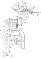
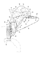
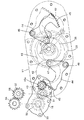
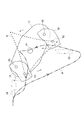
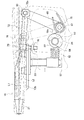
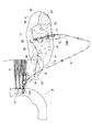
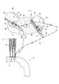
図1は本発明の一実施例に係る移植機の全体的な構成を示した側面図、図2は植付部の側面図、図3は苗植付爪部の側面図、図4はロータリケースの断面図、図5は苗植付爪の駆動説明図、図6は揺動カム部の説明図、図7は溝カム部の説明図、図8は植付爪部の平面説明図、図9は苗押出部材の説明図、図10は苗植付爪の軌跡の説明図、図11はロータリケースの側面説明図、図12は苗植付爪の側面説明図、図13は苗植付爪の0°、180°位置の説明図、図14は苗植付爪の45°、225°位置の説明図、図15は苗植付爪の90°、270°位置の説明図、図16は苗植付爪の135°、315°位置の説明図である。
Next, embodiments of the invention will be described.
FIG. 1 is a side view showing an overall configuration of a transplanter according to an embodiment of the present invention, FIG. 2 is a side view of a planting part, FIG. 3 is a side view of a seedling planting claw part, and FIG. Cross-sectional view of the case, FIG. 5 is a driving explanatory view of the seedling planting claw, FIG. 6 is an explanatory diagram of the swing cam portion, FIG. 7 is an explanatory diagram of the groove cam portion, FIG. 9 is an explanatory view of a seedling pushing member, FIG. 10 is an explanatory view of a locus of a seedling planting nail, FIG. 11 is a side explanatory diagram of a rotary case, FIG. 12 is a side explanatory diagram of a seedling planting nail, and FIG. FIG. 14 is an explanatory diagram of 45 ° and 225 ° positions of a seedling planting claw, FIG. 15 is an explanatory diagram of 90 ° and 270 ° positions of a planting claw, and FIG. 16 is an explanatory view of 135 ° and 315 ° positions of the seedling planting claws.

図1、図2に示す如く、移植機の移動車体1はフレームを前後に枠状に延設して、該移動車体1の後部上にエンジン2を搭載し、前下部に操向輪となる前車輪3を支承し、後下部に後車輪4を支承している。そして、移動車体1の後部にミッションケース5を配置して、前記エンジン2の出力軸よりミッションケース5を介して動力を伝達して後車輪4を駆動する。移動車体1の前部上には運転操作部6を設け、操向ハンドル7とその後部に運転席8を配置している。移動車体1の前後略中央の上方には予備苗台9を配置し、その下方に苗植付装置10を配置している。該苗植付装置10は昇降機構を介して昇降可能としており、移動車体1の略中央下側に前後昇降リンク11・12及び昇降シリンダ13を配置し昇降機構を構成している。苗植付装置10は左右往復移動する苗載台14と、苗載台14上の苗トレイ15より1株分のセル成形苗Nを取出して圃場の畝面に直接的に植付ける苗植付爪16とを備え、車体を走行させながら畝面上に一定間隔毎にセル成形苗Nを移植するように構成している。前記苗載台14は横送りネジ軸25及びガイドローラ26などを介して往復移動する構成とし、該苗載台14上に苗トレイ15を載置している。該苗トレイ15は碁盤の目状に凹部(ポット)を形成して、各凹部内に用土を充填して播種し、セル成形苗Nを育てるものである。   As shown in FIGS. 1 and 2, the moving vehicle body 1 of the transplanter has a frame extending in the front-and-rear direction, the engine 2 is mounted on the rear portion of the moving vehicle body 1, and the steering wheel is formed in the lower front portion. The front wheel 3 is supported and the rear wheel 4 is supported at the rear lower part. A transmission case 5 is disposed at the rear of the moving vehicle body 1, and power is transmitted from the output shaft of the engine 2 through the transmission case 5 to drive the rear wheels 4. A driving operation unit 6 is provided on the front portion of the moving vehicle body 1, and a driver's seat 8 is disposed on the steering handle 7 and the rear thereof. A reserve seedling stand 9 is arranged above the center of the moving vehicle body 1 in the front and rear, and a seedling planting device 10 is arranged therebelow. The seedling planting device 10 can be moved up and down via an elevating mechanism, and the elevating mechanism is configured by arranging the front and rear elevating links 11 and 12 and the elevating cylinder 13 on the lower side of the center of the movable vehicle body 1. The seedling planting apparatus 10 is a seedling planting system that takes out a cell-molded seedling N for one strain from a seedling stage 14 that reciprocates left and right and a seedling tray 15 on the seedling stage 14 and directly transplants the seedlings N on a farm surface. The nail | claw 16 is provided, and it is comprised so that the cell shaping | molding seedling N may be transplanted on a collar surface for every fixed interval, running a vehicle body. The seedling stage 14 is configured to reciprocate via a lateral feed screw shaft 25, a guide roller 26, and the like, and a seedling tray 15 is placed on the seedling stage 14. The seedling tray 15 forms concave portions (pots) in the shape of a grid, fills each concave portion with soil, and seeds the seedling tray 15 to grow cell-shaped seedlings N.

図3に示す如く、前記苗植付爪16は、1つの苗トレイ15に対し2つの苗植付爪16によりセル成形苗Nの取出し及び植付けを行うもので、同一植付軌跡A上で180度位相を異ならせて、1つの植付軌跡A中で二回の苗取り及び苗植付けを行って2株のセル成形苗Nを植付けて、苗植付速度を略2倍に増速させて高速植付作業を行うように構成している。   As shown in FIG. 3, the seedling planting claws 16 are used for taking out and planting the cell-molded seedlings N with respect to one seedling tray 15 by two seedling planting claws 16. The seedlings are planted twice in one planting trajectory A, and two cell-shaped seedlings N are planted, and the seedling planting speed is increased approximately twice. It is configured to perform high-speed planting work.

図3乃至図12に示す如く、前記苗植付装置10は、第1ロータリケース17の両側に第2ロータリケース18と爪ケース57と植付爪16をそれぞれを備え、第1ロータリケース17内に苗植付爪16を首振り動作させる首振り用溝カム19(図4参照)を設けている。苗植付爪16は左右爪体20・21を有して、開閉カム22の回動により開閉し(図8参照)、左右爪体20・21により挾持したセル成形苗Nを押出機構23により押し出すように構成している。押出機構23は苗押出カム24の回動により駆動するようにしている。   As shown in FIGS. 3 to 12, the seedling planting apparatus 10 includes a second rotary case 18, a claw case 57, and a planting claw 16 on both sides of the first rotary case 17. 4 is provided with a swing groove cam 19 (see FIG. 4) for swinging the seedling planting claw 16. The seedling planting claw 16 has left and right claw bodies 20 and 21 which are opened and closed by rotating the opening and closing cam 22 (see FIG. 8), and the cell-molded seedling N held by the left and right claw bodies 20 and 21 is pushed by an extrusion mechanism 23. It is configured to extrude. The pushing mechanism 23 is driven by the rotation of the seedling pushing cam 24.

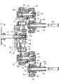
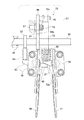
第1ロータリケース17は、図4、図5に示す如く、車体の固定ブラケット27などに駆動受軸28を介して取り付けており、該駆動受軸28に外筒軸32及び植付入力軸31を回転自在に支持させて、該植付入力軸31の一端にスプロケット29を固設している。そして、スプロケット29にチェン30を介して植付ミッションケースより動力を伝達する構成としている。一方、植付入力軸31の他端には外筒軸32をスプライン嵌合させ、前記第1ロータリケース17の中央に外筒軸32一端側を固定させている。第1ロータリケース17内の外筒軸32上にはサンギヤ38を遊嵌し、該サンギヤ38の一端を駆動受軸28に噛合又は機体側に固定させている。サンギヤ38はその両側の第1ロータリケース17に支持した中間軸41・41上に遊嵌したアイドルギヤ42・42と噛合させている。   As shown in FIGS. 4 and 5, the first rotary case 17 is attached to a fixed bracket 27 of the vehicle body via a drive receiving shaft 28, and the outer cylindrical shaft 32 and the planting input shaft 31 are attached to the drive receiving shaft 28. And a sprocket 29 is fixed to one end of the planting input shaft 31. And it is set as the structure which transmits motive power from the planting mission case to the sprocket 29 via the chain 30. On the other hand, the outer cylinder shaft 32 is spline fitted to the other end of the planting input shaft 31, and one end side of the outer cylinder shaft 32 is fixed to the center of the first rotary case 17. A sun gear 38 is loosely fitted on the outer cylindrical shaft 32 in the first rotary case 17, and one end of the sun gear 38 is engaged with the drive receiving shaft 28 or fixed to the body side. The sun gear 38 is engaged with idle gears 42 and 42 loosely fitted on intermediate shafts 41 and 41 supported by the first rotary case 17 on both sides thereof.

また、第1ロータリケース17両端に出力軸39・39を回転自在に支持させ、該第1ロータリケース17内で出力軸39上にプラネタリギヤ40を一体的に設け、該プラネタリギヤ40に前記アイドルギヤ42を噛合させている。そして、プラネタリギヤ40と、該プラネタリギア40とアイドルギヤ42を介して連結させる前記サンギヤ38とのギヤ比を1:3に形成して、第1ロータリケース17が一方向に1回転するとき出力軸39を逆方向に2回転させるように構成している。   Further, output shafts 39 and 39 are rotatably supported at both ends of the first rotary case 17, and a planetary gear 40 is integrally provided on the output shaft 39 in the first rotary case 17, and the idle gear 42 is attached to the planetary gear 40. Are engaged. The gear ratio between the planetary gear 40 and the sun gear 38 connected to the planetary gear 40 via the idle gear 42 is formed to be 1: 3, and the output shaft is rotated when the first rotary case 17 makes one rotation in one direction. 39 is configured to rotate twice in the reverse direction.

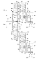
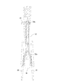
また、図4において、第1ロータリケース17の右側に第2ロータリケース18を配置し、第2ロータリケース18の一端側を前記出力軸39に固定させている。出力軸39には爪出力軸43を回転自在に内挿させ、爪出力軸43一端に形成したギヤ43aに、図6にも示す如く、揺動アーム44の一端側に形成した扇形状の部分ギヤ45を噛合させている。揺動アーム44は中間部を第1ロータリケース17に支点軸46を介して揺動自在に支持して、該揺動アーム44の他端側にローラ47を回転自在に支持させ、前記駆動受軸28に入力軸31を略中心として形成したエンドレス状の溝カム19内にローラ47を嵌合させて案内させるように構成している。   In FIG. 4, the second rotary case 18 is disposed on the right side of the first rotary case 17, and one end side of the second rotary case 18 is fixed to the output shaft 39. A claw output shaft 43 is rotatably inserted into the output shaft 39, and a fan-shaped portion formed on one end side of the swing arm 44 is formed on a gear 43a formed on one end of the claw output shaft 43 as shown in FIG. The gear 45 is engaged. The swing arm 44 is supported on the first rotary case 17 via a fulcrum shaft 46 so as to be swingable, and a roller 47 is rotatably supported on the other end side of the swing arm 44 so that the drive receiving A roller 47 is fitted and guided in an endless groove cam 19 formed on the shaft 28 with the input shaft 31 as a substantial center.

また、前記第2ロータリケース18内に臨ませて配置した爪出力軸43上にサンギヤ48を固定させ、該サンギヤ48に第2ロータリケース18の略中央に支持した中間軸51に回転自在に遊嵌した第1アイドルギヤ52を噛合させている。そして更に、第1アイドルギヤ52に第2ロータリケース18の他端に回動自在に支持した首振り軸49の一端に形成したプラネタリギヤである出力ギヤ50を噛合させている。また、パイプ状に構成した首振り軸49の軸心側に回転自在に内挿するカム軸53の一端にプラネタリギヤである出力ギヤ54を設け、該出力ギヤ54を前記第1アイドルギヤ52と一体的に構成した第2アイドルギヤ55と噛合させている。こうして爪出力軸43から首振り軸49とカム軸53を同時に駆動できるようにしている。   Further, a sun gear 48 is fixed on the claw output shaft 43 disposed so as to face the second rotary case 18, and the sun gear 48 is allowed to freely rotate on an intermediate shaft 51 supported substantially at the center of the second rotary case 18. The fitted first idle gear 52 is engaged. Further, the first idle gear 52 is meshed with an output gear 50 which is a planetary gear formed at one end of a swing shaft 49 rotatably supported at the other end of the second rotary case 18. An output gear 54, which is a planetary gear, is provided at one end of a cam shaft 53 that is rotatably inserted on the axial center side of a swing shaft 49 configured in a pipe shape, and the output gear 54 is integrated with the first idle gear 52. The second idle gear 55 is configured to be meshed. Thus, the swinging shaft 49 and the cam shaft 53 can be driven simultaneously from the claw output shaft 43.

前記サンギヤ48と第1アイドルギヤ52及び第2アイドルギヤ55と出力ギヤ54を同一歯数で、第1アイドルギヤ52と出力ギヤ50のギヤ比を2:3として、首振り軸49の出力ギヤ50とカム軸53の出力ギヤ54の回転差が一回転となるように設定し、首振り軸49に連結する苗植付爪16の揺動時にはカム軸53を苗植付爪16に対し常に一定回転させる状態とさせて、無理のない溝カム19形状で、カム軸53に固設する開閉カム22及び苗押出カム24のスムーズな回転を行うように構成している。   The sun gear 48, the first idle gear 52, the second idle gear 55, and the output gear 54 have the same number of teeth, and the gear ratio of the first idle gear 52 and the output gear 50 is 2: 3. 50 and the output gear 54 of the camshaft 53 is set so that the rotation difference is one rotation. When the seedling planting claw 16 connected to the swing shaft 49 is swung, the camshaft 53 is always moved with respect to the seedling planting claw 16. In the state of constant rotation, the groove cam 19 has a reasonable shape, and the opening / closing cam 22 and the seedling push cam 24 fixed to the cam shaft 53 are smoothly rotated.

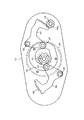
そして、図10にも示す如く、入力軸31を中心とした第1ロータリケース17の反時計方向(実線矢印方向)の一回転に対し爪出力軸43を中心として第2ロータリケース18を時計方向(破線矢印方向)に二回転させ、第1ロータリケース17の一回転(第2ロータリケース18の二回転)によって苗植付爪16の支点部となるカム軸53に図10におけるKに示す如き略3角形状の植付基本軌跡Kを描かせるように構成している。   As shown in FIG. 10, the second rotary case 18 is rotated clockwise about the claw output shaft 43 with respect to one rotation of the first rotary case 17 about the input shaft 31 in the counterclockwise direction (solid arrow direction). As shown by K in FIG. 10, the camshaft 53 serving as a fulcrum portion of the seedling planting claw 16 is rotated twice in the direction of the broken line arrow and rotated once by the first rotary case 17 (two rotations of the second rotary case 18). A substantially triangular planting basic locus K is drawn.

さらに、図5、図8に示す如く、第2ロータリケース18の右側に爪ケース57を配置し、第2ロータリケース18に支持した前記首振り軸49一端側に爪ケース57を固定させている。図8、図12に示す如く、爪ケース57にはカム軸53に対して直角方向に左右の開閉軸58・59を支持させている。該左右開閉軸58・59は図12において爪ケース57より上方に突出し、該左右開閉軸58・59の一端(上端)にそれぞれ左右爪体20・21を固定している。また、該左右開閉軸58・59の他側(下部)にはそれぞれ左右開閉板60・61を左右中央側に突出するように固定して、中央で係合する構成としている。そして、爪ケース57に凹部を形成し、該凹部内に開用コイルバネ62を収納させ、該開用コイルバネ62の他側を一方の開閉板61に当接させている。即ち、開閉板60・61と爪ケース57との間に開用コイルバネ62を介設させて、該開用コイルバネ62の付勢力により開閉板60・61を押して爪体20・21を開く方向に付勢させている。また、一方の(左の)開閉軸58には他方(左)の開閉板60と反対側に開閉用操作板63を突出して設けて、中間部材64の先端に当接するように配置している。   Further, as shown in FIGS. 5 and 8, a claw case 57 is disposed on the right side of the second rotary case 18, and the claw case 57 is fixed to one end side of the swing shaft 49 supported by the second rotary case 18. . As shown in FIGS. 8 and 12, the claw case 57 supports left and right opening and closing shafts 58 and 59 in a direction perpendicular to the cam shaft 53. The left and right open / close shafts 58 and 59 protrude upward from the claw case 57 in FIG. Further, left and right opening / closing plates 60 and 61 are fixed to the other side (lower part) of the left and right opening / closing shafts 58 and 59 so as to protrude to the left and right center sides, respectively, and engaged at the center. A recess is formed in the claw case 57, the opening coil spring 62 is accommodated in the recess, and the other side of the opening coil spring 62 is brought into contact with one open / close plate 61. That is, an opening coil spring 62 is interposed between the opening / closing plates 60 and 61 and the claw case 57, and the opening / closing plates 60 and 61 are pushed by the biasing force of the opening coil spring 62 to open the claw bodies 20 and 21. Energized. Further, one (left) opening / closing shaft 58 is provided with an opening / closing operation plate 63 protruding from the other (left) opening / closing plate 60 so as to contact the tip of the intermediate member 64. .

また、前記首振り軸49より爪ケース57内にカム軸53を突出させて、該カム軸53上に板状開閉カム22と後述する苗押出カム24を平行に固定し、開閉カム22と前記開閉用操作板63との間に中間部材64を配置している。該中間部材64は爪ケース57に摺動自在に支持し、該中間部材64の一端側を開閉用操作板63に当接させ、他端側を開閉カム22の外周面に当接させている。該開閉カム22には大径部と小径部を有し、小径部に中間部材64の一端が当接しているときに爪体20・21が開くようにしている。   Further, the cam shaft 53 is projected from the swing shaft 49 into the claw case 57, and the plate-like opening / closing cam 22 and a seedling push-out cam 24, which will be described later, are fixed in parallel on the cam shaft 53. An intermediate member 64 is disposed between the opening / closing operation plate 63. The intermediate member 64 is slidably supported on the claw case 57, one end side of the intermediate member 64 is brought into contact with the opening / closing operation plate 63, and the other end side is brought into contact with the outer peripheral surface of the opening / closing cam 22. . The opening / closing cam 22 has a large-diameter portion and a small-diameter portion, and the claws 20 and 21 are opened when one end of the intermediate member 64 is in contact with the small-diameter portion.

このような構成において、カム軸53の回動により開閉カム22を回転させて、中間部材64を大径部に当接させると、中間部材64が爪体20・21側へ押されて摺動し、該中間部材64の摺動により開閉用操作板63が押されて左開閉軸58が回動し、該左開閉軸58に固定された左爪体20が反時計回りに回転する。この回転により左開閉板60も回転して右開閉板61を押し、右開閉軸59が回転して、該右開閉軸59に固設した右爪体21が時計回りに回転する。こうして爪体20・21を閉じることができ、セル成形苗Nを挟持することができる。この状態からカム軸53が逆方向に回転すると、開閉カム22の回転により、中間部材64は大径部から小径部に当接する。このとき開用コイルバネ62の付勢力により、右開閉板61を常時開方向に付勢しているため、この付勢力により押されて、右爪体21が反時計回りに回転し、この回転により左開閉板60が押されて左爪体20が時計回り回転して、爪体20・21が開く。   In such a configuration, when the opening / closing cam 22 is rotated by the rotation of the cam shaft 53 and the intermediate member 64 is brought into contact with the large diameter portion, the intermediate member 64 is pushed and slid toward the claws 20 and 21 side. Then, the opening / closing operation plate 63 is pushed by the sliding of the intermediate member 64 to rotate the left opening / closing shaft 58, and the left claw body 20 fixed to the left opening / closing shaft 58 rotates counterclockwise. By this rotation, the left opening / closing plate 60 also rotates to push the right opening / closing plate 61, the right opening / closing shaft 59 rotates, and the right claw body 21 fixed to the right opening / closing shaft 59 rotates clockwise. Thus, the claws 20 and 21 can be closed, and the cell molded seedling N can be held. When the cam shaft 53 rotates in the opposite direction from this state, the intermediate member 64 contacts the small diameter portion from the large diameter portion by the rotation of the opening / closing cam 22. At this time, since the right opening / closing plate 61 is constantly urged in the opening direction by the urging force of the opening coil spring 62, the right claw member 21 is rotated counterclockwise by being pushed by this urging force. When the left opening / closing plate 60 is pushed, the left nail body 20 rotates clockwise, and the nail bodies 20 and 21 open.

また、前記左右爪体20・21の間にはセル成形苗Nを押出す苗押出部材72を配設し、押出機構23により苗押出部材72を往復駆動するように構成している。図8、図9、図12に示す如く、該苗押出部材72は先端部72bを二股状に形成して平面視Y字状に構成し、他側端に輪状に形成した基端部72aを設けている。そして、基端部72aに押出アーム66の先端に固設した軸65を挿入して、苗押出部材72を押出アーム66に枢支させるとともに、押出アーム66他端の基部側を爪ケース57に支持したアーム軸67に枢支させている。アーム軸67はカム軸53と平行に配置して、左右爪体20・21とはカム軸53に対して前後反対側に配置している。押出アーム66と爪ケース57との間には弾性部材としてバネ70を介装してアーム軸67上に外嵌させ、該バネ70の付勢力により押出アーム66を左右爪体20・21側へ回動させるように付勢している。そして、押出アーム66の基端部にカム軸53側へ突出する凸部66aを形成している。   A seedling extruding member 72 for extruding the cell-molded seedling N is disposed between the left and right claws 20 and 21, and the seedling extruding member 72 is reciprocally driven by the extrusion mechanism 23. As shown in FIGS. 8, 9, and 12, the seedling extruding member 72 has a distal end portion 72b formed in a bifurcated shape to form a Y shape in plan view, and a base end portion 72a formed in a ring shape on the other end. Provided. Then, a shaft 65 fixed to the distal end of the extrusion arm 66 is inserted into the base end portion 72a so that the seedling extrusion member 72 is pivotally supported by the extrusion arm 66, and the base side of the other end of the extrusion arm 66 is attached to the claw case 57. The supported arm shaft 67 is pivotally supported. The arm shaft 67 is disposed in parallel with the cam shaft 53, and the left and right claws 20, 21 are disposed on the opposite side with respect to the cam shaft 53. A spring 70 is interposed as an elastic member between the push arm 66 and the claw case 57 and is fitted on the arm shaft 67. The push arm 66 is moved toward the left and right claws 20 and 21 by the biasing force of the spring 70. It is energized to rotate. A protrusion 66 a that protrudes toward the cam shaft 53 is formed at the base end of the push arm 66.

一方、前記カム軸53上において、前記開閉カム22よりも外側に前記凸部66aに対向して苗押出カム24を固設し、該苗押出カム24の外周面に凸部66aを当接させている。該苗押出カム24は大径部と小径部を有し、凸部66aが大径部と当接しているときには押出アーム66を後退した位置に回動させ、苗押出カム24の回転作用で凸部66aが苗押出カム24の小径部と当接すると、バネ70の付勢力により押出アーム66を左右爪体20・21側へ回動させて、苗押出部材72を左右爪体20・21に沿って進出摺動させる。こうして、苗押出カム24の回動により苗押出部材72を往復移動させることができるようにしている。   On the other hand, on the camshaft 53, the seedling push cam 24 is fixedly provided on the outer side of the opening / closing cam 22 so as to face the convex portion 66a, and the convex portion 66a is brought into contact with the outer peripheral surface of the seedling push cam 24. ing. The seedling push cam 24 has a large diameter portion and a small diameter portion. When the convex portion 66 a is in contact with the large diameter portion, the push arm 66 is rotated to the retracted position, and the seedling push cam 24 rotates by the rotational action. When the portion 66a comes into contact with the small diameter portion of the seedling push cam 24, the pushing arm 66 is rotated to the left and right claws 20/21 by the biasing force of the spring 70, and the seedling push member 72 is moved to the left and right claws 20/21. Advancing and sliding along. Thus, the seedling pushing member 72 can be reciprocated by the rotation of the seedling pushing cam 24.

前記苗押出部材72はゴム或いは樹脂材などの弾性を有する部材で構成し、先端部72bを先端側が開く二股状に形成して、左右爪体20・21の間に配置し、先端部72bの先端を左右爪体20・21の内側に摺接させている。   The seedling extruding member 72 is made of an elastic member such as rubber or a resin material, and the tip portion 72b is formed in a bifurcated shape with the tip side open, and is disposed between the left and right nails 20 and 21, and the tip portion 72b The tip is in sliding contact with the inside of the left and right claws 20 and 21.

そして、図12において、左右爪体20・21の上下中心線L1が水平方向に位置しているとすると、苗押出部材72の中心線L2を下方に(爪ケース57側)に傾斜して配置し、中心線L1・L2の交点が左右爪体20・21の先端に位置するように構成している。このように構成することにより、セル成形苗Nの根鉢部分を左右爪体20・21で挟持したときに、セル成形苗Nが水平に位置した状態で茎や葉の部分が苗押出部材72上に位置するようになって、左右爪体20・21の中心線とセル成形苗Nの中心線が略一致するようになり、搬送するときに、セル成形苗Nの姿勢が崩れることないのである。そして、畝上へ搬送して、苗押出部材72の摺動により押し出す時に、苗押出部材72の先端部72bがちょうど根鉢部分が当たるようになり、正確に移植することができるのである。   Then, in FIG. 12, if the vertical center line L1 of the left and right nail bodies 20, 21 is positioned in the horizontal direction, the center line L2 of the seedling pushing member 72 is inclined downward (on the nail case 57 side). In addition, the intersection of the center lines L1 and L2 is configured to be positioned at the tips of the left and right claws 20 and 21. With this configuration, when the root pot portion of the cell molded seedling N is sandwiched between the left and right nail bodies 20 and 21, the stem and leaf portions are the seedling extruding member 72 while the cell molded seedling N is positioned horizontally. Since the center line of the left and right nail bodies 20 and 21 and the center line of the cell molded seedling N are substantially coincident with each other, the posture of the cell molded seedling N is not collapsed when transported. is there. When the seedling extruding member 72 is pushed out by sliding on the ridge, the tip 72b of the seedling extruding member 72 just comes into contact with the root pot portion and can be transplanted accurately.

また、図12に示す如く、ガイド75により前記苗押出部材72の長手方向中途部を位置規制させている。即ち、該ガイド75は苗植付爪16の後部(左右爪体20・21と反対側)に位置して爪ケース57に取り付けている。該ガイド75の上部は苗押出部材72の基部側のロッド部の外形に合わせた環状に構成して、苗押出部材72の基部側のロッド部を挿入している。ガイド75の下部は雄ネジに構成し、爪ケース57の上部に螺装してロックナット76により高さ調節可能に固定できるように構成している。つまり、ガイド75の高さを調整することにより前記苗押出部材72の中心線L2の傾斜角度を調節できるようにしている。こうして、苗押出部材72を摺動させるときに上下左右をガイド75で規制することで位置がずれることがなく確実に苗押出しを行うように構成している。そして、苗押出部材72を下動させるときには、苗押出部材72先端部72bは左右爪体20・21の内面に沿って摺動することになり、セル成形苗Nを押出すと同時に爪体20・21内面に付着する養土や土を落すことができるのである。   In addition, as shown in FIG. 12, the position of the midway portion in the longitudinal direction of the seedling extruding member 72 is regulated by a guide 75. That is, the guide 75 is attached to the nail case 57 at the rear portion (on the opposite side to the left and right nail bodies 20 and 21) of the seedling planting nail 16. The upper part of the guide 75 is formed in an annular shape matching the outer shape of the rod part on the base side of the seedling pushing member 72, and the rod part on the base side of the seedling pushing member 72 is inserted. The lower part of the guide 75 is formed as a male screw, and is screwed into the upper part of the claw case 57 so as to be fixed by a lock nut 76 so that the height can be adjusted. That is, by adjusting the height of the guide 75, the inclination angle of the center line L2 of the seedling pushing member 72 can be adjusted. In this way, when the seedling pushing member 72 is slid, the top, bottom, left, and right are regulated by the guide 75 so that the seedling is pushed out reliably without being displaced. When the seedling extruding member 72 is moved downward, the tip end portion 72b of the seedling extruding member 72 slides along the inner surfaces of the left and right nail bodies 20 and 21, so that the nail body 20 is simultaneously extruded with the cell molded seedling N being extruded.・ Can remove soil and soil adhering to the inner surface of 21.

以上のような構成において、苗載台14をガイドローラ26などを介し左右方向に往復摺動させて、取出位置付近で苗トレイ15を略垂直姿勢に保持し、苗トレイ15の開口取出側を後方に位置させ、苗載台14後方に配置した苗植付爪16を後方下側より略水平に苗トレイ15のポット内に突入させてセル成形苗Nの取出しを行うようにしている。この際、図3、図10、図13乃至図16に示す如く、第1ロータリケース17が入力軸31を中心として反時計方向(実線矢印方向)に一回転するとき、第2ロータリケース18は出力軸43を中心として時計方向(破線矢印方向)に二回転する。この回転中において、図6に示す如く、第1ロータリケース17の受軸28に設けた首振り用溝カム19に揺動アーム44の一端に設けたローラ47を転動自在に嵌合させて、揺動アーム44を支点軸46を中心に揺動させ、該揺動アーム44の他端に設けた部分ギヤ45と噛合するギヤ43aを回転させる。この回転により爪出力軸43のサンギヤ48が第1アイドルギヤ52及び第2アイドルギヤ55を回動し、第1アイドルギヤ52に噛合した出力ギヤ50により爪ケース57が揺動して、苗植付爪16が首振り動作する。このときのカム軸53の回動軌跡が図3に示す如き略3角形の基本軌跡Kとなり、苗植付爪16の先端の回動軌跡が苗植付軌跡Aとなる。   In the configuration as described above, the seedling stage 14 is slid back and forth in the left-right direction via the guide roller 26 and the like, the seedling tray 15 is held in a substantially vertical position near the extraction position, and the opening extraction side of the seedling tray 15 is The cell-molded seedling N is taken out by placing the seedling planting claws 16 located behind and placed behind the seedling mounting table 14 into the pot of the seedling tray 15 substantially horizontally from the lower rear side. At this time, as shown in FIGS. 3, 10, 13 to 16, when the first rotary case 17 makes one rotation counterclockwise (solid arrow direction) around the input shaft 31, the second rotary case 18 is The output shaft 43 is rotated twice in the clockwise direction (the direction of the broken arrow). During this rotation, as shown in FIG. 6, a roller 47 provided at one end of the swing arm 44 is fitted to the swing groove cam 19 provided in the receiving shaft 28 of the first rotary case 17 so as to be freely rotatable. The swing arm 44 is swung around the fulcrum shaft 46, and the gear 43a meshing with the partial gear 45 provided at the other end of the swing arm 44 is rotated. By this rotation, the sun gear 48 of the claw output shaft 43 rotates the first idle gear 52 and the second idle gear 55, and the claw case 57 is swung by the output gear 50 meshed with the first idle gear 52, so The pawl 16 swings. The rotation locus of the cam shaft 53 at this time is a substantially triangular basic locus K as shown in FIG. 3, and the rotation locus of the tip of the seedling planting claw 16 is a seedling planting locus A.

具体的に説明すると、二つの苗植付爪16A・16Bの一方の苗植付爪16Aを、図13に示す如く、苗トレイ15の凹部に挿入させときには、苗植付爪16Aは略水平方向の状態で、左右の爪体20・21を開いた状態で挿入する。このとき第1ロータリケース17及び第2ロータリケース18は一直線上に水平方向に並んでいる。そして、第1ロータリケース17が先端が下方へ回動するときに、第2ロータリケース18は逆回転しているために逆方向(後方)に略水平方向で戻るように動き、セル成形苗Nが苗トレイ15などに接して落ちないようにしている。このときに開閉カム22の回転により、爪体20・21が閉じて、図14に示す如く、苗植付爪16Aがセル成形苗Nの根鉢をつかみ苗トレイ15からセル成形苗Nを抜き取る。   More specifically, when one seedling planting claw 16A of the two seedling planting claws 16A and 16B is inserted into the concave portion of the seedling tray 15, as shown in FIG. In this state, the left and right claws 20 and 21 are inserted in an open state. At this time, the first rotary case 17 and the second rotary case 18 are aligned in a horizontal line on a straight line. When the tip of the first rotary case 17 rotates downward, the second rotary case 18 moves in a reverse direction (backward) in a substantially horizontal direction because the second rotary case 18 rotates in the reverse direction. Is prevented from falling in contact with the seedling tray 15 or the like. At this time, the claw bodies 20 and 21 are closed by the rotation of the opening / closing cam 22, and the seedling planting claws 16A grasp the root pot of the cell-molded seedling N and extract the cell-molded seedling N from the seedling tray 15 as shown in FIG. .

そして、第1ロータリケース17の下方への回動と第2ロータリケース18の回動とにより、図15に示す如く、苗植付爪16Aは徐々に下方に姿勢を変える。そして、図16に示す如く、苗植付爪16Aが鉛直方向を向いた位置において、開閉カム22の回転により、爪体20・21が開くと同時に、苗押出カム24の回転により押出アーム66を回動して苗押出部材72を爪体20・21側に摺動させてセル成形苗Nを圃場上に押し出すのである。この苗押出部材72の二股に分かれた先端部72bは爪体20・21の内面に接して配設されているため、苗押出部材72の往復摺動時に爪体20・21内面に付着した土等を擦って落すことができ、土等の付着を防止できるのである。   Then, by the downward rotation of the first rotary case 17 and the rotation of the second rotary case 18, the seedling planting claws 16A gradually change their postures downward as shown in FIG. Then, as shown in FIG. 16, at the position where the seedling planting claw 16 </ b> A is oriented in the vertical direction, the claw bodies 20 and 21 are opened by the rotation of the opening / closing cam 22, and at the same time, the pushing arm 66 is moved by the rotation of the seedling pushing cam 24. It rotates and slides the seedling extruding member 72 toward the claws 20 and 21 to push out the cell-molded seedling N onto the field. Since the bifurcated tip 72b of the seedling extruding member 72 is disposed in contact with the inner surface of the claw body 20, 21, the soil adhered to the inner surface of the claw body 20, 21 when the seedling extruding member 72 reciprocates. Etc. can be rubbed off, and adhesion of soil etc. can be prevented.

そして、第1ロータリケース17が上方へ回動するととともに第2ロータリケース18も回動して、図13の苗植付爪16Bの如く、苗植付爪16Aは略下方から若干後下方を向いたまま上昇する。このように、垂直方向を向いたまま苗植付爪16を上昇させることにより、セル成形苗Nの植付姿勢が変化せず、苗植付爪16の回動により倒すようなことも防ぐのである。このとき、第1ロータリケース17は半回転し、第2ロータリケース18は略一回転することになる。苗押出部材72は苗植付爪16Aが十分持ち上げられた位置で、苗押出カム24の回転により元の位置に戻る。   Then, as the first rotary case 17 is rotated upward, the second rotary case 18 is also rotated, and the seedling planting claws 16A are directed from the substantially lower side to the slightly lower rear side as in the seedling planting claws 16B of FIG. It rises as it is. Thus, by raising the seedling planting claw 16 while facing the vertical direction, the planting posture of the cell-molded seedling N does not change, and it is possible to prevent the seedling planting claw 16 from being tilted by the rotation of the seedling planting claw 16. is there. At this time, the first rotary case 17 is rotated halfway, and the second rotary case 18 is rotated approximately once. The seedling extruding member 72 is returned to the original position by the rotation of the seedling extruding cam 24 at the position where the seedling planting claws 16A are sufficiently lifted.

さらに、第1ロータリケース17が回動して、図14、図15、図16の苗植付爪16Bの如く、苗植付爪16Aは垂直方向を向いた状態から徐々に水平方向を向いて、元の位置に戻り、第1ロータリケース17は一回転し、第2ロータリケース18は二回転することになる。   Further, the first rotary case 17 rotates so that the seedling planting claws 16A gradually turn in the horizontal direction from the vertically oriented state as in the seedling planting claws 16B in FIGS. Returning to the original position, the first rotary case 17 rotates once and the second rotary case 18 rotates twice.

以上のように、本発明の移植機は、苗載台14上に載置した苗トレイ15に収納したセル成形苗Nを取出して圃場に植付ける苗植付爪16と、苗植付時に苗植付爪16より苗を押出す苗押出部材72とを備え、中央の左右方向の植付入力軸31を中心として回転する第1ロータリケース17と、第1ロータリケース17両端の出力軸39に基端を連結させる第2ロータリケースとを設け、第2ロータリケース18先端の首振り軸49に前記苗植付爪16を取り付けて、苗植付爪の支点部を略3角形状の軌跡Kで移動させる構成としたものであるから、苗植付爪16による苗取出し時にはセル成形苗Nを苗植付爪16で傷つけることなく良好に苗植付爪16を突入させ、苗トレイ15より上方のセル成形苗Nを乱すことなくスムーズにセル成形苗Nを抜出して苗取出し精度を向上できる。また、第1ロータリケース17の一回転時に第2ロータリケース18を介する2つの苗植付爪16で二回の苗植付けを行って高速植付作業を容易に可能とさせることができる。   As described above, the transplanting machine of the present invention takes out the cell-molded seedling N stored in the seedling tray 15 placed on the seedling stage 14 and transplants it into the field, and the seedling planting claws 16 and seedlings at the time of seedling planting. A seedling extruding member 72 for extruding seedlings from the planting claws 16; a first rotary case 17 that rotates about a planting input shaft 31 in the center left-right direction; and output shafts 39 at both ends of the first rotary case 17 A second rotary case for connecting the base ends, the seedling planting claw 16 is attached to the swing shaft 49 at the tip of the second rotary case 18, and the fulcrum portion of the seedling planting claw is a substantially triangular locus K Therefore, when the seedlings are taken out by the seedling planting claws 16, the seedling planting nails 16 are plunged well without damaging the cell-molded seedlings N with the seedling planting nails 16, and above the seedling tray 15. Cell molding smoothly without disturbing the cell molding seedling N It can be improved seedling precision withdrawn N. Further, at the time of one rotation of the first rotary case 17, two seedling planting claws 16 through the second rotary case 18 are used to plant seedlings twice so that high-speed planting work can be easily performed.

また、前記苗植付爪16に挟持する苗の押出しを行う苗押出部材72を苗植付爪16の左右爪体20・21の内側に配設させて、苗押出部材72の移動方向と苗植付爪16に挟持したセル成形苗Nの向きとをずらして苗押出部材72によりセル成形苗Nが曲げられることを防止し、植付姿勢不良などのない精度良好な苗植付けを容易に可能とさせることができる。さらに、苗押出部材72を苗植付爪16の内側に保護して耐久性を向上させることができる。   Further, a seedling extruding member 72 for extruding the seedling sandwiched between the seedling planting nails 16 is disposed inside the left and right nails 20 and 21 of the seedling planting nails 16, and the moving direction of the seedling extruding member 72 and the seedlings are arranged. The orientation of the cell-molded seedling N sandwiched between the planting claws 16 is shifted to prevent the cell-molded seedling N from being bent by the seedling pushing member 72, and it is possible to easily plant seedlings with good accuracy without any planting posture failure. It can be made. Furthermore, durability can be improved by protecting the seedling extruding member 72 inside the seedling planting claws 16.

また、前記苗植付爪16の内側に配置した苗押出部材72を苗植付爪16に対して傾斜させ、苗取出し時には苗植付爪16で根鉢部分を挟持したセル成形苗Nの茎や葉の部分を苗押出部材72上に位置させて、苗押出部材72によるセル成形苗Nの損傷を防止できる。また、苗押出部材72で確実に根鉢部分を押して苗植付爪16からセル成形苗Nを押出させることができため、苗植付け精度を向上させることができる。   Further, the seedling extruding member 72 disposed inside the seedling planting nail 16 is inclined with respect to the seedling planting nail 16, and the stem of the cell-molded seedling N having the root pot portion sandwiched between the seedling planting nails 16 at the time of seedling removal. The leaf portion is positioned on the seedling extruding member 72, so that the cell shaped seedling N can be prevented from being damaged by the seedling extruding member 72. Moreover, since the cell-shaped seedling N can be pushed out from the seedling planting claws 16 by reliably pushing the root pot portion with the seedling pushing member 72, the seedling planting accuracy can be improved.

さらに、前記苗押出部材72の先端を二股状に形成して、苗植付爪16の左右爪体20・21の内面に付着する土など付着物も苗植付時に良好に除去して苗取出し精度を向上させることができる。   Furthermore, the tip of the seedling extruding member 72 is formed in a bifurcated shape, and dirt and other deposits adhering to the inner surfaces of the left and right nails 20 and 21 of the seedling planting claws 16 are removed well during seedling planting to remove seedlings. Accuracy can be improved.

本発明の一実施例に係る移植機の全体的な構成を示した側面図。The side view which showed the whole structure of the transplanter which concerns on one Example of this invention. 植付部の側面図。The side view of a planting part. 苗植付爪部の側面図。The side view of a nail | claw part with seedling planting. ロータリケースの断面図。Sectional drawing of a rotary case. 苗植付爪の駆動説明図。Drive explanatory drawing of a seedling planting nail. 揺動カム部の説明図。Explanatory drawing of a rocking cam part. 溝カム部の説明図。Explanatory drawing of a groove cam part. 植付爪部の平面説明図。Plane explanatory drawing of a planting nail | claw part. 苗押出部材の説明図。Explanatory drawing of a seedling extrusion member. 苗植付爪の軌跡の説明図。Explanatory drawing of the locus | trajectory of a seedling planting nail. ロータリケースの側面説明図。Side surface explanatory drawing of a rotary case. 苗植付爪の側面説明図。Side surface explanatory drawing of a seedling planting nail. 苗植付爪の0°、180°位置の説明図。Explanatory drawing of 0 degree and 180 degree position of a seedling planting nail. 苗植付爪の45°、225°位置の説明図。Explanatory drawing of the 45 degrees and 225 degrees position of a seedling planting nail. 苗植付爪の90°、270°位置の説明図。Explanatory drawing of the 90 degree | times and 270 degree position of a seedling planting nail | claw. 苗植付爪の135°、315°位置の説明図。Explanatory drawing of 135 degrees and 315 degrees position of a seedling planting nail.

符号の説明Explanation of symbols

14 苗載台
15 苗トレイ
16 苗植付爪
17 第1ロータリケース(ロータリ部材)
18 第2ロータリケース(ロータリ部材)
72 苗押出部材
14 Seedling stand 15 Seedling tray 16 Nail with seedling 17 First rotary case (rotary member)
18 Second rotary case (rotary member)
72 Seedling Extrusion Member

Claims (4)

苗載台上に載置した苗トレイに収納したセル成形苗を取出して圃場に植付ける苗植付爪と、苗植付時に苗植付爪より苗を押出す苗押出部材とを備えた移植機であって、中央の左右方向の回転軸を中心として回転する第1ロータリ部材と、第1ロータリ部材両端の出力軸に基端を連結させる第2ロータリ部材とを設け、第2ロータリ部材先端の出力軸に前記苗植付爪を取り付けて、苗植付爪の支点部を略3角形状の軌跡Kで移動させる構成としたことを特徴とする移植機。   Transplantation with cell-planted seedlings stored in a seedling tray placed on a seedling stand and planted in a field and seedling extruding members that extrude seedlings from seedling planting nails when planting seedlings A first rotary member that rotates about a central rotation axis in the left-right direction, and a second rotary member that connects base ends to output shafts at both ends of the first rotary member. The transplanting machine is configured to attach the seedling planting claw to the output shaft of the plant and move the fulcrum part of the seedling planting claw along a locus K having a substantially triangular shape. 前記苗押出部材を苗植付爪の内側に配設したことを特徴とする請求項1に記載の移植機。   The transplanter according to claim 1, wherein the seedling extruding member is disposed inside a seedling planting claw. 前記苗押出部材を苗植付爪に対して傾斜させたことを特徴とする請求項2に記載の移植機。   The transplanting machine according to claim 2, wherein the seedling extruding member is inclined with respect to the seedling planting nail. 前記苗押出部材の先端を二股状に形成したことを特徴とする請求項3に記載の移植機。
The transplanter according to claim 3, wherein the seedling extruding member has a bifurcated tip.
JP2004121189A 2004-04-16 2004-04-16 Transplanter Pending JP2005295967A (en)

Priority Applications (1)

Application Number Priority Date Filing Date Title
JP2004121189A JP2005295967A (en) 2004-04-16 2004-04-16 Transplanter

Applications Claiming Priority (1)

Application Number Priority Date Filing Date Title
JP2004121189A JP2005295967A (en) 2004-04-16 2004-04-16 Transplanter

Publications (1)

Publication Number Publication Date
JP2005295967A true JP2005295967A (en) 2005-10-27

Family

ID=35328260

Family Applications (1)

Application Number Title Priority Date Filing Date
JP2004121189A Pending JP2005295967A (en) 2004-04-16 2004-04-16 Transplanter

Country Status (1)

Country Link
JP (1) JP2005295967A (en)

Cited By (1)

* Cited by examiner, † Cited by third party
Publication number Priority date Publication date Assignee Title
JP2015533481A (en) * 2012-09-05 2015-11-26 ▲東▼北▲農▼▲業▼大学 Transplanting mechanism for combined rice bot seedlings

Cited By (1)

* Cited by examiner, † Cited by third party
Publication number Priority date Publication date Assignee Title
JP2015533481A (en) * 2012-09-05 2015-11-26 ▲東▼北▲農▼▲業▼大学 Transplanting mechanism for combined rice bot seedlings

Similar Documents

Publication Publication Date Title
JP5290741B2 (en) Seedling transplanter
JP2005295967A (en) Transplanter
JP2005295966A (en) Transplanter
JP4220927B2 (en) Ride type transplanter
JP4061324B2 (en) Vegetable transplanter
JP3821735B2 (en) Vegetable transplanter
JP2002017119A (en) Seedling transplanter
JP4462552B2 (en) Multi-row type transplanter
JP4010501B2 (en) Vegetable transplanter
JP3821737B2 (en) Vegetable transplanter
JP2002017121A (en) Implanting device of transplanter
JP4056058B2 (en) Vegetable transplanter
JP3821736B2 (en) Vegetable transplanter
JP4162647B2 (en) Transplanter
JP4126142B2 (en) Vegetable transplanter
JP2003274713A (en) Vegetable transplanter
JP4056059B2 (en) Vegetable transplanter
JP2001314106A (en) Seedling transplanter
JPH1189331A (en) Transplant machine
JP3044538B2 (en) Transplant machine
JP2600054B2 (en) Seedling plant in rice transplanter
JP2004049068A (en) Vegetable transplanter
JP2001314108A (en) Walking seedling transplanter
JP2017060516A (en) Transplanter
JP2003274712A (en) Vegetable transplanter

Legal Events

Date Code Title Description
A621 Written request for application examination

Free format text: JAPANESE INTERMEDIATE CODE: A621

Effective date: 20061221

A977 Report on retrieval

Effective date: 20080630

Free format text: JAPANESE INTERMEDIATE CODE: A971007

A131 Notification of reasons for refusal

Free format text: JAPANESE INTERMEDIATE CODE: A131

Effective date: 20080708

A02 Decision of refusal

Free format text: JAPANESE INTERMEDIATE CODE: A02

Effective date: 20081118