JP2006123793A - Coupling structure - Google Patents
Coupling structure Download PDFInfo
- Publication number
- JP2006123793A JP2006123793A JP2004316028A JP2004316028A JP2006123793A JP 2006123793 A JP2006123793 A JP 2006123793A JP 2004316028 A JP2004316028 A JP 2004316028A JP 2004316028 A JP2004316028 A JP 2004316028A JP 2006123793 A JP2006123793 A JP 2006123793A
- Authority
- JP
- Japan
- Prior art keywords
- vehicle body
- cowl top
- restricting means
- piece
- panel
- Prior art date
- Legal status (The legal status is an assumption and is not a legal conclusion. Google has not performed a legal analysis and makes no representation as to the accuracy of the status listed.)
- Granted
Links
- 230000008878 coupling Effects 0.000 title abstract description 5
- 238000010168 coupling process Methods 0.000 title abstract description 5
- 238000005859 coupling reaction Methods 0.000 title abstract description 5
- 239000011521 glass Substances 0.000 abstract description 21
- 239000005357 flat glass Substances 0.000 description 17
- 239000000428 dust Substances 0.000 description 6
- 230000001105 regulatory effect Effects 0.000 description 4
- 210000000078 claw Anatomy 0.000 description 3
- 238000004378 air conditioning Methods 0.000 description 1
- 230000000903 blocking effect Effects 0.000 description 1
- 230000001771 impaired effect Effects 0.000 description 1
- 239000000463 material Substances 0.000 description 1
- 238000007789 sealing Methods 0.000 description 1
- 229920003002 synthetic resin Polymers 0.000 description 1
- 239000000057 synthetic resin Substances 0.000 description 1
Images

Landscapes
- Body Structure For Vehicles (AREA)
Abstract
Description
本発明は、フロントウインドガラスとフロントフード(ボンネット)との間のカウルトップ部を覆うカウルトップカバーであって、特に複数のパネルを組み合わせて構成するカウルトップカバーの相隣する2つのパネルの連結構造に関する。 The present invention relates to a cowl top cover that covers a cowl top portion between a front window glass and a front hood (bonnet), and in particular, the connection of two adjacent panels of a cowl top cover configured by combining a plurality of panels. Concerning structure.
従来、自動車のカウルトップ部には外気を車室に取り入れるための空気入れ口や、ワイパーを駆動するための駆動軸などが設けられている。これらを保護し、雨水や塵埃の侵入を防止するために、カウルトップ部の上面には同カウルトップ部を被覆するカウルトップカバーが、略全車幅にわたって取付けられている。 2. Description of the Related Art Conventionally, a cowl top portion of an automobile is provided with an air inlet for taking outside air into a passenger compartment, a drive shaft for driving a wiper, and the like. In order to protect these and prevent the intrusion of rainwater and dust, a cowl top cover that covers the cowl top is attached to the upper surface of the cowl top over substantially the entire vehicle width.
このカウルトップカバーの本体は合成樹脂材料から成形されており、従来は略全車幅にわたる長尺一体物も使用されていたが、例えばフロントウインドガラスの曲面に倣って弯曲させると共にその車体の左右端部に向けて前後寸法を漸増させるような形状等が求められるようになったことから、車幅方向で分割された複数のパネルを連結して使用するカウルトップカバーが出現するようになってきた。 The body of the cowl top cover is molded from a synthetic resin material. Conventionally, an elongate unit covering almost the entire vehicle width has been used. For example, the cowl top cover is bent along the curved surface of the front window glass and the right and left ends of the vehicle body. Since a shape that gradually increases the front-rear dimension toward the part is required, a cowl top cover that uses a plurality of panels divided in the vehicle width direction has come to appear. .
このようなカウルトップカバーは、例えば、特許文献1及び特許文献2に開示されているものがある。
特許文献1によれば、カウルトップカバーは本体を車幅方向に左右2つに分割して2枚の左右半部に形成されている。左右半部はそれぞれ後端縁に沿って、フロントウインドガラスの下端縁を支持する爪部を間欠的に有している。
According to
また、各半部の前端縁は立設された立壁部と同立壁部の上縁から車体前方に延設された取付け片とを有し、同取付け片の下面にはピンが突設されており、カウルトップ部の前記ピンに対応する位置には、同ピンを挿入するために車幅方向に長孔状の取付け孔が形成されている。 Further, the front end edge of each half has a standing wall portion and a mounting piece extending from the upper edge of the standing wall portion to the front of the vehicle body, and a pin projects from the lower surface of the mounting piece. In the cowl top portion, a mounting hole having a long hole shape is formed in the vehicle width direction in order to insert the pin at a position corresponding to the pin.
前記右半部の連結側端縁には、同端縁から略L字型をなすフランジが端縁位置を前方及び下方にずらした状態で延設されており、前記フランジには車体の前後方向に延設する長孔が形成されている。 A flange having a substantially L-shape is extended from the end edge of the right half portion with the end position shifted forward and downward, and the flange extends in the longitudinal direction of the vehicle body. A long hole is formed to extend to.
前記左半部の連結側端縁には前記長孔に対応する位置にピンが突設されており、前記左半部はその端縁を前記右半部の前記フランジ上面に重ねて前記ピンを前記長孔に挿通して位置決めし、両者を連結している。 A pin is projected from the connecting edge of the left half at a position corresponding to the long hole, and the left half is overlapped with the flange upper surface of the right half. The long hole is inserted and positioned, and both are connected.
前記右半部は、上記取付け片の前記ピンをカウルトップ部の前記取付け孔に挿入して位置決めすると共に、前記爪部にフロントウインドガラスの下端部を嵌入させて車体に取付けられる。 The right half part is attached to the vehicle body by inserting the pin of the attachment piece into the attachment hole of the cowl top part and fitting the lower end part of the front window glass into the claw part.
次いで、前記左半部の連結側端縁に突設された前記ピンを前記右半部のフランジに、車体前後方向に沿って形成された前記長孔に挿入して、同左半部を車体前後方向に移動させながら、フロントウインドガラスの下端縁を嵌入させて車体に取付けられる。 Next, the pin projecting from the connection side edge of the left half is inserted into the long hole formed in the longitudinal direction of the vehicle body on the flange of the right half, and the left half is While moving in the direction, the lower edge of the front window glass is fitted and attached to the vehicle body.
このとき更に、同左半部の取付け部に形成された前記ピンをカウルトップ部の前記取付け孔に挿入して、同左半部が車体に対して位置決めされる。 At this time, the pin formed in the attachment portion of the left half is further inserted into the attachment hole of the cowl top portion, and the left half is positioned with respect to the vehicle body.
しかしながら、上記カウルトップカバーの車体への取付けは、フロントウインドガラスの下端縁をカウルトップカバー本体の後端縁に形成された爪部により部分的に支持しているに過ぎず、またカウルトップカバー本体の前端縁に突設されたピンは単にカウルトップ部の取付け孔に挿入されて車体に対して位置決めするに過ぎないため、車体の上下方向及び前後方向における規制がなされていない。 However, the attachment of the cowl top cover to the vehicle body is only partially supported by the claw portion formed at the rear edge of the cowl top cover body, and the cowl top cover is also supported by the lower end edge of the front window glass. The pins projecting from the front end edge of the main body are merely inserted into the mounting holes of the cowl top portion and positioned with respect to the vehicle body, and thus are not restricted in the vertical direction and the front-rear direction of the vehicle body.
そこで、カウルトップカバーは、全体板状に形成され、特にメッシュ状の開口が一体又は別体で形成される場合には、車体へ取付けた後にもカウルトップカバー全体にねじれや波打ちが生じることがあり、この結果、連結部同士に隙間が生じることになって、外観が低下すると共に、塵埃や枯れ葉などが前記隙間からカウルトップ内部に侵入して、車体側の空気取り入れ口から空調ボックスに入り込むことになり、或いは雨水の排水路を塞ぐなどの課題を未解決のまま残している。 Therefore, the cowl top cover is formed in an overall plate shape, and particularly when the mesh-shaped opening is formed integrally or separately, the cowl top cover may be twisted and wavy even after being attached to the vehicle body. As a result, a gap is generated between the connecting parts, the appearance is deteriorated, dust and dead leaves enter the cowl top through the gap, and enter the air conditioning box from the air intake on the vehicle body side. In other words, problems such as blocking the drainage of rainwater remain unsolved.
そこで、上記の課題を解決するために、特許文献2に開示されたカウルトップカバーが提案されている。
Therefore, in order to solve the above problems, a cowl top cover disclosed in
特許文献2によれば、カウルトップカバーを右半部と左半部との二分割構成し、右半部は左半部との連結側端縁の裏面から段差を持って左半部の裏面に当接する板状の連結部が延設されている。
According to
一方、左半部は前記連結部に当接する裏面の近傍すなわち左半部の連結側端縁から前記連結部の長さよりも僅かに長い他端縁側に入った位置に前記連結側端縁と平行する突条が形成されている。 On the other hand, the left half portion is parallel to the connection side edge in the vicinity of the back surface in contact with the connection portion, that is, from the connection side edge of the left half portion to the other end edge side slightly longer than the length of the connection portion. A protruding ridge is formed.
従って、この突条が左半部の連結側端縁の近傍に形成されているために、カウルトップカバー全体に波打ちなどの経時的変形が生じた場合にも、各端縁の形態が維持されて変形を防止されるように意図とされている。 Therefore, since the protrusion is formed in the vicinity of the connection side edge of the left half, the shape of each edge is maintained even when the entire cowl top cover is deformed over time, such as waving. It is intended to prevent deformation.
しかしながら、上記特許文献2に開示されたカウルトップカバーにおいては、前記左半部側の前記突条は、前記右半部側の連結部の端縁に当接しない構造にしているために、両半部の連結部において、車体上下方向が隙間なく規制されているという構成ではないといえ、このために、突条の耐変形力より大きな変形力が生じた場合に、やはり両連結部側端縁において隙間が生じるおそれが有り、万一隙間が生じた場合には、外観を損なってしまうことにもなりかねず、また当該隙間から塵埃や枯れ葉等のカウルトップ内部への侵入を防止しきれないおそれもあった。
However, in the cowl top cover disclosed in
そこで、上記の課題を解決するために、特許文献3に開示されたカウルトップカバーが知られている。
特許文献3に記載されたカウルトップカバーは、カウルトップカバー本体の左右半部に連結部を形成して、左右両半部の連結側端縁同士を連結するように構成している。
The cowl top cover described in
すなわち、左半部の連結側端縁の連結部は、同連結部の本体部分に形成された矩形状の開口を有し、この開口部裏面周囲に連結側の側壁部開放する3面の側壁と底部とからなるボックス状凹部から構成し、ボックス状凹部の底部には車幅方向に沿って長孔が形成されている。 That is, the connecting portion at the connecting side edge of the left half has a rectangular opening formed in the main body portion of the connecting portion, and the three side walls that open the connecting side wall portion around the back of the opening. The bottom of the box-shaped recess is formed with a long hole along the vehicle width direction.
また、右半部の連結部は、前記ボックス状凹部に対応する位置に前記底部を載置するように形成されたL字状の連結片からなり、同連結片の水平部には車幅方向に沿って長孔が形成されている。 The right half of the connecting portion is formed of an L-shaped connecting piece formed so as to place the bottom portion at a position corresponding to the box-shaped recess, and the horizontal portion of the connecting piece has a vehicle width direction. A long hole is formed along.
そして、前記長孔同士に、連結部材のクリップ状の連結片部を嵌入することによって、左右両半部の車体上下方向の規制を行うようにすると共に、連結部材における連結片部一端側に頭部を形成して、該頭部により前記ボックス状凹部の開口部を閉塞するように構成している。 And by inserting the clip-like connecting piece portion of the connecting member into the long holes, the left and right half portions are regulated in the vehicle body vertical direction, and the head is positioned at one end of the connecting piece portion of the connecting member. A portion is formed, and the opening of the box-shaped recess is closed by the head.
しかしながら、特許文献3に記載されたカウルトップカバーは、左右両半部にそれぞれ設けた長孔同士に、連結部材のクリップ状の連結片部を嵌入することによって、左右両半部の車体上下方向の規制を行うという構成を採るために、連結片部により左右両半部の連結部における車体上下方向及び左右方向の規制は確実に施されている反面、左右両半部に経時的な変形等により相対的に車体前後方向の力が加わった場合、連結片部を軸として左右半部が相対的に移動するおそれがあり、このために、車体前後方向の規制に対して未だ完全ではないといえる。
However, in the cowl top cover described in
そこで、本発明は、かかる点に鑑み、複数のパネルを組み合わせて構成するカウルトップカバーの相隣する2つのパネルを、車体の左右方向や上下方向ばかりでなく車体前後方向に確実に規制された構成とする連結構造を提供することを目的としている。 Therefore, in view of such a point, the present invention reliably restricts two adjacent panels of a cowl top cover configured by combining a plurality of panels not only in the lateral direction and the vertical direction of the vehicle body but also in the longitudinal direction of the vehicle body. It aims at providing the connection structure made into a structure.
上記目的を達成するために、請求項1に記載の本発明に係る連結構造は、複数のパネルを組み合わせて構成するカウルトップカバーの相隣する2つのパネルを連結する連結構造であって,上下方向と左右方向と前後方向のうち、一の方向に前記2つのパネルの相対的進退位置を規制する第一の進退位置規制手段と、上下方向と左右方向と前後方向のうち、他の一の方向に前記2つのパネルの相対的進退位置を規制する第二の進退位置規制手段と、上下方向と左右方向と前後方向のうち、更に他の一の方向のうち少なくとも一方向に2つのパネルの相対的進退位置を規制する第三の進退位置規制手段とを具備したことを特徴とする。
In order to achieve the above object, a connection structure according to the present invention described in
上記のように構成する本発明によれば、相隣する2つのパネルの連結部分において、上下方向と左右方向と前後方向のうち、第一の進退位置規制手段により一方の方向に2つのパネルの相対的進退位置が規制され、第二の進退位置規制手段により他の一方の方向に2つのパネルの相対的進退位置が規制され、更に、第三の進退位置規制手段により更に他の一の方向の少なくとも一方向に2つのパネルの相対的進退位置が規制されることになって、両分割カウルトップカバー片が経時的な変形によって相対的に車体上下方向、車体前後方向及び車体左右方向にたとえ変形しようとしても、当該変形力が、前記第一ないし第三の進退位置規制手段によって受け止められて、前記連結部における隙間等が発生することがなく、外観を損なってしまうことなく、また塵埃や枯れ葉等がカウルトップ内部へ侵入することを確実に防止することができる。 According to the present invention configured as described above, in the connecting portion between two adjacent panels, the first forward / backward position restricting means among the two panels in one direction among the vertical direction, the horizontal direction, and the front-rear direction. The relative advance / retreat position is restricted, the relative advance / retreat position of the two panels is restricted in the other direction by the second advance / retreat position restricting means, and further the other one direction by the third advance / retreat position restricting means. The relative advancing and retreating positions of the two panels are regulated in at least one direction, so that the two split cowl top cover pieces are relatively deformed in the vertical direction of the vehicle body, the longitudinal direction of the vehicle body, and the lateral direction of the vehicle body. Even if it tries to deform, the deformation force is received by the first to third advance / retreat position restricting means, and a gap or the like in the connecting portion is not generated, and the appearance is damaged. And without and may be dust, dead leaves or the like is reliably prevented from entering the inside the cowl top.
以下、図を用いて、本発明を実施するための一実施の形態について説明する。 Hereinafter, an embodiment for carrying out the present invention will be described with reference to the drawings.
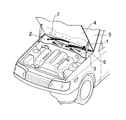
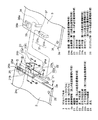
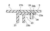
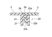
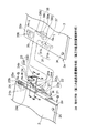
図1は本発明に係るカウルトップカバーが取り付けられた車両の斜視図、図2は図1におけるカウルトップカバー本体の連結部分を拡大して描画した分割斜視図、図3は図2のA−A断面図、図4は図2のB−B断面図、図5は図2のC−C断面図、図6は図2のD−D断面図である。 1 is a perspective view of a vehicle to which a cowl top cover according to the present invention is attached, FIG. 2 is an enlarged perspective view of a coupling portion of the cowl top cover main body in FIG. 1, and FIG. 4 is a sectional view taken along the line BB in FIG. 2, FIG. 5 is a sectional view taken along the line CC in FIG. 2, and FIG. 6 is a sectional view taken along the line DD in FIG.
カウルトップカバー1は、右半部のパネル2と左半部のパネル3とに二分割されて、カウルトップカバー1の前端部にはシール部材6が、後縁部にはエンドラバー7が取付けられている。
The
カウルトップカバー1は図示せぬクリップ等の固着具により車体に取付けられ、シール部材6はフロントフード4に、エンドラバー7はフロントウインドガラス5の下縁部にそれぞれ密着してシールされる。
The
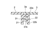
右半部のパネル2は左半部のパネル3との連結側端部2aには縦壁21が形成されており、縦壁部21に、その上端部に後述の左半部のパネル3の板厚とほぼ同寸法の段差部21bが形成されるように、逆L字状片部22を形成しており、逆L字状片部22の左右方向延在部22aの一端が縦壁21に連結して、他端が上下方向延在部22bの一端が連結しており、上下方向延在部22bと縦壁部21との間は所定の隙間を有して、下方が開口された係合隙間部27を形成している。
The
逆L字状片部22の上下方向延在部22bには、左右方向延在部22aに連続するように水平座部23aが形成されていると共に、水平座部23a車体後端縁側に垂直壁23bが連続して形成されて、水平座部23aと垂直壁23bとによって取付け台座部23を構成している。
A
水平座部23aには、その車体前縁端側が開口する長孔24が形成されており、長孔24の開口部24aは開口幅が拡大形成されている。
The
右半部のパネル2の車体後端部側には、フロントウインドガラス5の端部を係着する略コ字状を呈するガラスクリップ体25が一体的に形成されている。
A
ガラスクリップ体25は、後端縁側先端部25aが右半部のパネル2の下面に対して隙間25bを有しており、隙間25b内にフロントウインドガラス5の下端部を嵌入することによりフロントウインドガラス5を支着している。
The
右半部のパネル2の車体前端縁部側には、右半部のパネル2を車体に取り付ける為のクリップ孔26が複数箇個形成されている。
A plurality of clip holes 26 for attaching the
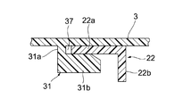
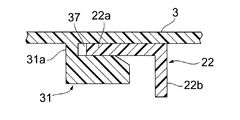
左半部のパネル3の裏面部には、L字状係合片部31が形成されている。L字状係合片部31は、垂直片部31aと水平片部31bとで構成され、垂直片部31aの上端が左半部のパネル3の裏面部に連結しており、他端部には水平片部31bの一端側が連結し、水平片部31bの他端側は車体後方側に延在しており、水平片部31bと左半部のパネル3の裏面部とは係合隙間37が形成されている。
An L-shaped
この結果、係合隙間37に逆L字状片部22の左右方向延在部22aが係合するように構成されていると共に、係合片部31の水平片部31bが係合隙間27内に係入するように構成されている。
As a result, the left and right
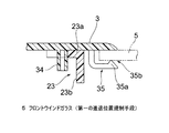
また、左半部のパネル3の裏面部には、係合片部31に対して車体後方且つ連結側端部3aとは反対側に離間した位置に、取付けピン34を立設しており、取付けピン34は取付け台座部23の水平座部23aに形成した長孔24に嵌合するように構成されている。
Further, a mounting
更に、左半部のパネル3の裏面部における車体後端部側には、右半部のパネル2と同様に、フロントウインドガラス5の端部を係着する略コ字状を呈するガラスクリップ体35が一体的に形成されている。
Further, on the rear end side of the vehicle body on the back surface of the
ガラスクリップ体35は、後端縁側先端部35aが左半部のパネル3の下面に対して隙間35bを有しており、隙間35b内にフロントウインドガラス5の下端部を嵌入することによりフロントウインドガラス5を支着している。
The
左半部のパネル3の車体前端縁部側には、左半部のパネル3を車体に取り付ける為のクリップ孔36が複数箇個形成されている。
A plurality of clip holes 36 for attaching the
上記のように構成する場合、カウルトップカバー1を車体に取付ける場合、先ず、フロントウインドガラス5の端部をガラスクリップ体25の隙間25bに嵌合すると共に、クリップ孔26に車体側に装着したクリップを係合することにより、右半部のパネル2を車体に取付け、カウルトップ部の略半分を覆っておく。
When the cowl
次に、右半部のパネル2における逆L字状片部22の上下方向延在部22bと縦壁部21との間に形成された係合隙間27に係合片部31の水平片部31bを係合すると共に、取付けピン34を開口部24aから長孔24内に嵌合し、更に、フロントウインドガラス5の端部をガラスクリップ体35の隙間35bに嵌合すると共に、クリップ孔36に車体側に装着したクリップを係合することにより、左半部のパネル3を車体に取付け、カウルトップ部の残りの略半分を覆い、左半部のパネル3の連結側端部3aが右半部のパネル2における縦壁部21の段差部21bに突き当たって、右半部のパネル2と左半部のパネル3とがほぼ段差なく連結されることになる。
Next, the horizontal piece portion of the
また、左半部のパネル3側における係合片部31の水平片部31bが係合隙間27に係入して、水平片部31bの上面が逆L字状片部22における左右方向延在部22aの下面部に当接すると共に、フロントウインドガラス5の下端部がガラスクリップ体25の隙間25b及びガラスクリップ体35の隙間35bに嵌入して、ガラスクリップ体25の後端縁側先端部25a及びガラスクリップ体35の後端縁側先端部35aがフロントウインドガラス5の上面に当接することにより、右半部のパネル2に対する左半部のパネル3の車体上下方向の相対的進退位置を規制する第一の進退位置規制手段が形成されることになる。
Further, the
したがって、第一の進退位置規制手段は、逆L字状片部22における左右方向延在部22a及びフロントウインドガラス5と、左半部のパネル3における係合片部31の水平片部31b及びガラスクリップ体25,35とによって構成されることになる。
Therefore, the first advancing / retreating position restricting means includes the left-right
また、取付けピン34が長孔24の左右側壁24cに当接すると共に、左半部のパネル3の係合片部31が逆L字状片部22の上下方向延在部22bに突き当たり、更に左半部のパネル3の連結側端部3aが右半部のパネル2の段差部21bに突き当たることによって、右半部のパネル2に対する左半部のパネル3の車体左右方向の相対的進退位置を規制する第二の進退位置規制手段が形成されることになる。
Further, the mounting
したがって、第二の進退位置規制手段は、右半部のパネル2における取付け台座部23の長孔24の左右側壁24c、右半部のパネル2における段差部21b及び逆L字状片部22の上下方向延在部22bと、左半部のパネル3における取付けピン34、左半部のパネル3における係合片部31及び連結側端部3aとによって構成されることになる。
Therefore, the second advancing / retreating position restricting means includes the left and
この状態において、取付けピン34が長孔24の奥壁24bに当接することによって、右半部のパネル2に対する左半部のパネル3の車体後方向の相対的進退位置を規制する第三の進退位置規制手段が形成されることになる。
In this state, when the mounting
したがって、第三の進退位置規制手段は、右半部のパネル2における長孔24の奥壁24bと左半部のパネル3における取付けピン34とで構成されることになる。
Therefore, the third forward / backward position restricting means is constituted by the
かかる構成を有する本発明にかかる一の実施の形態によれば、逆L字状片部22における左右方向延在部22a及びガラスクリップ体25と左半部のパネル3における係合片部31の水平片部31b及びガラスクリップ体35とがそれぞれ当接することによって、右半部のパネル2及び左半部のパネル3の連結部分の相対的進退位置を規制する第一の進退位置規制手段が形成され、また、右半部のパネル2における長孔24の左右側壁24c、段差部21b及び上下方向延在部22bが第2の車体前後方向規制部位である取付けピン34、係合片部31及び連結側端部3aにそれぞれ当接することによって、右半部のパネル2及び左半部のパネル3の連結部分の相対的進退位置を規制する第二の進退位置規制手段が形成され、更に、右半部のパネル2における長孔24の奥壁24bが左半部のパネル3における取付けピン34に当接することによって、右半部のパネル2及び左半部のパネル3の連結部分の相対的進退位置を規制する第三の進退位置規制手段が形成されることになって、左右半部のパネル2,3が経時的な変形によって相対的に車体上下方向、車体左右方向及び車体前後方向にたとえ変形しようとしても、当該変形力が、前記第一から第三の進退位置規制手段によって受け止められて、前記連結部における隙間等が発生することがなく、外観を損なってしまうことなく、また塵埃や枯れ葉等がカウルトップ内部へ侵入することを確実に防止することができる。
According to one embodiment of the present invention having such a configuration, the left-right
図7乃至図12は本発明の他の実施の形態を示している。 7 to 12 show another embodiment of the present invention.
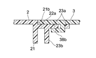
図7乃至図12によれば、上記実施の形態における取付けピン34に代えて、取付け体38にした点以外は、上記実施の形態と同様の構成を有して構成している。
According to FIGS. 7-12, it replaces with the
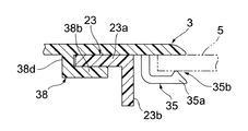
取付け体38は、左半部のパネル3の連結側端部3a及び後端部側が開口する平面視略L字状の取付け座部38aと取付け座部38aの下端部に連結された底辺部38bとから構成している。
The
そして、取付け座部38aの車体前後方向延在片部38cを長孔24内に嵌入し、車体左右方向延在片部38dを長孔24の開口部24aの先端部壁24dに当接するに構成されている。
The vehicle seat longitudinally extending
上記一の実施の形態と同様に、右半部のパネル2の逆L字状片部22における左右方向延在部22a及びガラスクリップ体25と、左半部のパネル3における係合片部31の水平片部31b及びガラスクリップ体35とによって車体上下方向の相対的進退位置を規制すると共に、更に左半部のパネル3の取付け体38の底辺部38bの上面が右半部のパネル2の取付台座部23の水平座部23aの下面に当接することによって、右半部のパネル2に対する左半部のパネル3の車体上下方向の相対的進退位置を規制する第一の進退位置規制手段が形成されることになる。
Similarly to the above-described one embodiment, the left-right
また、取付け体38の車体前後方向延在片部38cが長孔24の左右側壁24cに当接すると共に、左半部のパネル3の係合片部31の水平片部31bが逆L字状片部22の上下方向延在部22bに突き当たり、更に左半部のパネル3の連結側端部3aが右半部のパネル2の段差部21bに突き当たることによって、右半部のパネル2に対する左半部のパネル3の車体左右方向規制部が形成されることになる。
Further, the vehicle body longitudinally extending
また、取付け座部38aの車体前後方向延在片部38cが長孔24の奥壁24bに当接することによって、右半部のパネル2に対する左半部のパネル3の車体後方向の相対的進退位置を規制する第三の進退位置規制手段が形成されることになる。
In addition, the vehicle body longitudinally extending
以上説明したように、本発明は、相隣する2つのパネルの連結部分において、上下方向と左右方向と前後方向のうち、第一の進退位置規制手段により一方の方向に2つのパネルの相対的進退位置が規制され、第二の進退位置規制手段により他の一方の方向に2つのパネルの相対的進退位置が規制され、更に、第三の進退位置規制手段により更に他の一の方向の少なくとも一方向に2つのパネルの相対的進退位置が規制されることになって、両分割カウルトップカバー片が経時的な変形によって相対的に車体上下方向、車体前後方向及び車体左右方向にたとえ変形しようとしても、当該変形力が、前記第一ないし第三の進退位置規制手段によって受け止められて、前記連結部における隙間等が発生することがなく、外観を損なってしまうことなく、また塵埃や枯れ葉等がカウルトップ内部へ侵入することを確実に防止することができるために、フロントウインドガラスとフロントフード(ボンネット)との間のカウルトップ部を覆うカウルトップカバーであって、特に複数のパネルを組み合わせて構成するカウルトップカバーの相隣する2つのパネルの連結構造等に好適である。 As described above, according to the present invention, in the connecting portion of two adjacent panels, the first panel is relatively moved in one direction by the first advancing / retreating position regulating means among the vertical direction, the horizontal direction, and the front-rear direction. The forward / backward position is restricted, the relative forward / backward position of the two panels is restricted in the other direction by the second forward / backward position restricting means, and further, at least in the other direction by the third forward / backward position restricting means. The relative advance and retreat positions of the two panels in one direction will be restricted, so that both split cowl top cover pieces will be deformed in the vertical direction of the vehicle body, the longitudinal direction of the vehicle body, and the lateral direction of the vehicle body relative to the deformation over time. However, the deformation force is received by the first to third advance / retreat position restricting means, and a gap or the like in the connecting portion is not generated, and the appearance is not impaired. And a cowl top cover that covers the cowl top between the windshield and the front hood (bonnet) in order to reliably prevent dust and dead leaves from entering the cowl top. Particularly, it is suitable for a connecting structure of two adjacent panels of a cowl top cover configured by combining a plurality of panels.
1 カウルトップ本体
2 右半部のパネル
3 左半部のパネル
3a 連結側端部(第二の進退位置規制手段)
5 フロントウインドガラス(第一の進退位置規制手段)
21 縦壁部
21b 段差部(第二の進退位置規制手段)
22 逆L字状片部
22a 左右方向延在部
22b 上下方向延在部(第二の進退位置規制手段)
23 取付け台座部
24 長孔
24b 奥壁(第三の進退位置規制手段)
24c 左右側壁(第二の進退位置規制手段)
25 ガラスクリップ体(第一の進退位置規制手段)
31 係合片部
31a 垂直片部
31b 水平片部(第一の進退位置規制手段)
34 取付けピン(第二の進退位置規制手段)(第三の進退位置規制手段)
35 ガラスクリップ体(第一の進退位置規制手段)
38 取付け体(第二の進退位置規制手段)(第三の進退位置規制手段)
DESCRIPTION OF
5 Front window glass (first advance / retreat position regulating means)
21
22 Inverted L-shaped
23 mounting
24c Left and right side walls (second advance / retreat position restricting means)
25 Glass clip body (first advance / retreat position restricting means)
31
34 mounting pin (second advance / retreat position restricting means) (third advance / retreat position restricting means)
35 Glass clip body (first advance / retreat position restricting means)
38 Attachment body (second advance / retreat position restricting means) (third advance / retreat position restricting means)
Claims (1)
上下方向と左右方向と前後方向のうち、一の方向に前記2つのパネルの相対的進退位置を規制する第一の進退位置規制手段と、
上下方向と左右方向と前後方向のうち、他の一の方向に前記2つのパネルの相対的進退位置を規制する第二の進退位置規制手段と、
上下方向と左右方向と前後方向の更に他の一の方向のうち少なくとも一方向に2つのパネルの相対的進退位置を規制する第三の進退位置規制手段と、
を具備したことを特徴とする連結構造。 A connecting structure for connecting two adjacent panels of a cowl top cover configured by combining a plurality of panels,
A first advancing / retreating position restricting means for restricting a relative advancing / retreating position of the two panels in one direction among the up / down direction, the left / right direction, and the front / rear direction;
A second advancing / retreating position restricting means for restricting the relative advancing / retreating position of the two panels in the other direction among the up / down direction, the left / right direction, and the front / rear direction;
A third advancing / retreating position restricting means for restricting the relative advancing / retreating position of the two panels in at least one direction among the up-down direction, the left-right direction, and another one direction of the front-rear direction;
The connection structure characterized by comprising.
Priority Applications (1)
| Application Number | Priority Date | Filing Date | Title |
|---|---|---|---|
| JP2004316028A JP4700325B2 (en) | 2004-10-29 | 2004-10-29 | Connected structure |
Applications Claiming Priority (1)
| Application Number | Priority Date | Filing Date | Title |
|---|---|---|---|
| JP2004316028A JP4700325B2 (en) | 2004-10-29 | 2004-10-29 | Connected structure |
Publications (2)
| Publication Number | Publication Date |
|---|---|
| JP2006123793A true JP2006123793A (en) | 2006-05-18 |
| JP4700325B2 JP4700325B2 (en) | 2011-06-15 |
Family
ID=36718923
Family Applications (1)
| Application Number | Title | Priority Date | Filing Date |
|---|---|---|---|
| JP2004316028A Expired - Fee Related JP4700325B2 (en) | 2004-10-29 | 2004-10-29 | Connected structure |
Country Status (1)
| Country | Link |
|---|---|
| JP (1) | JP4700325B2 (en) |
Cited By (2)
| Publication number | Priority date | Publication date | Assignee | Title |
|---|---|---|---|---|
| JP2006224758A (en) * | 2005-02-16 | 2006-08-31 | Fuji Heavy Ind Ltd | Split cowl panel |
| JP2009241896A (en) * | 2008-03-31 | 2009-10-22 | Nippon Plast Co Ltd | Cowl top cover |
Citations (8)
| Publication number | Priority date | Publication date | Assignee | Title |
|---|---|---|---|---|
| JPS57108480U (en) * | 1980-12-19 | 1982-07-05 | ||
| JPS6280177A (en) * | 1985-10-02 | 1987-04-13 | 本田技研工業株式会社 | Exterior plate connection structure |
| JPH0562386A (en) * | 1991-09-05 | 1993-03-12 | Mitsubishi Electric Corp | Control device of magnetic disk device |
| JPH0596935A (en) * | 1991-10-07 | 1993-04-20 | Toyota Motor Corp | Cowl louver structure |
| JPH0880869A (en) * | 1994-09-13 | 1996-03-26 | Aichi Mach Ind Co Ltd | Connection part structure of divided type cowl top cover |
| JPH10211891A (en) * | 1997-01-30 | 1998-08-11 | Nippon Plast Co Ltd | Mounting structure for cowl top cover |
| JP2000344138A (en) * | 1999-06-07 | 2000-12-12 | Nippon Plast Co Ltd | Cowl top cover |
| JP2003172095A (en) * | 2001-12-05 | 2003-06-20 | Technos Kk | Coupling device for segment |
-
2004
- 2004-10-29 JP JP2004316028A patent/JP4700325B2/en not_active Expired - Fee Related
Patent Citations (8)
| Publication number | Priority date | Publication date | Assignee | Title |
|---|---|---|---|---|
| JPS57108480U (en) * | 1980-12-19 | 1982-07-05 | ||
| JPS6280177A (en) * | 1985-10-02 | 1987-04-13 | 本田技研工業株式会社 | Exterior plate connection structure |
| JPH0562386A (en) * | 1991-09-05 | 1993-03-12 | Mitsubishi Electric Corp | Control device of magnetic disk device |
| JPH0596935A (en) * | 1991-10-07 | 1993-04-20 | Toyota Motor Corp | Cowl louver structure |
| JPH0880869A (en) * | 1994-09-13 | 1996-03-26 | Aichi Mach Ind Co Ltd | Connection part structure of divided type cowl top cover |
| JPH10211891A (en) * | 1997-01-30 | 1998-08-11 | Nippon Plast Co Ltd | Mounting structure for cowl top cover |
| JP2000344138A (en) * | 1999-06-07 | 2000-12-12 | Nippon Plast Co Ltd | Cowl top cover |
| JP2003172095A (en) * | 2001-12-05 | 2003-06-20 | Technos Kk | Coupling device for segment |
Cited By (2)
| Publication number | Priority date | Publication date | Assignee | Title |
|---|---|---|---|---|
| JP2006224758A (en) * | 2005-02-16 | 2006-08-31 | Fuji Heavy Ind Ltd | Split cowl panel |
| JP2009241896A (en) * | 2008-03-31 | 2009-10-22 | Nippon Plast Co Ltd | Cowl top cover |
Also Published As
| Publication number | Publication date |
|---|---|
| JP4700325B2 (en) | 2011-06-15 |
Similar Documents
| Publication | Publication Date | Title |
|---|---|---|
| CN102910207B (en) | Vehicle body structure for automobile | |
| US20150151791A1 (en) | Cowl section structure for vehicle | |
| JP6528526B2 (en) | Fixed structure of glass run | |
| JP5916065B2 (en) | Cowl cover device | |
| CN104837660A (en) | Window module | |
| JP6125476B2 (en) | Molding for vehicle and mounting structure for molding in vehicle | |
| JP4700325B2 (en) | Connected structure | |
| JP4858408B2 (en) | Glass run | |
| JP4489722B2 (en) | Vehicle side structure | |
| JP5798082B2 (en) | Belt molding and its mounting structure | |
| JP6803318B2 (en) | Cowl top garnish | |
| US20150069787A1 (en) | Cowl-top cover | |
| JP2009107446A (en) | Side step molding for vehicles | |
| JP4331131B2 (en) | Vehicle mudguard and its mounting structure | |
| JP2006176070A (en) | Cowl louver | |
| JP2011098646A (en) | Weatherstrip installing structure of automobile | |
| JP4781900B2 (en) | Cowl top cover | |
| JP6347700B2 (en) | Vehicle seal member assembly structure | |
| JP6543521B2 (en) | Mounting structure of automotive door seal | |
| JP4053488B2 (en) | Cowl top garnish structure | |
| JP7488206B2 (en) | Cowl cover device | |
| JP2006315561A (en) | Vehicle body door structure | |
| JP2008543635A (en) | Wind deflector for sliding roof | |
| US9216634B1 (en) | Rocker seal attachment structure | |
| JP2006131011A (en) | Sealing structure |
Legal Events
| Date | Code | Title | Description |
|---|---|---|---|
| A621 | Written request for application examination |
Free format text: JAPANESE INTERMEDIATE CODE: A621 Effective date: 20070510 |
|
| A131 | Notification of reasons for refusal |
Free format text: JAPANESE INTERMEDIATE CODE: A131 Effective date: 20090812 |
|
| A977 | Report on retrieval |
Free format text: JAPANESE INTERMEDIATE CODE: A971007 Effective date: 20090820 |
|
| A521 | Request for written amendment filed |
Free format text: JAPANESE INTERMEDIATE CODE: A523 Effective date: 20091013 |
|
| A131 | Notification of reasons for refusal |
Free format text: JAPANESE INTERMEDIATE CODE: A131 Effective date: 20100330 |
|
| A521 | Request for written amendment filed |
Free format text: JAPANESE INTERMEDIATE CODE: A523 Effective date: 20100510 |
|
| TRDD | Decision of grant or rejection written | ||
| A01 | Written decision to grant a patent or to grant a registration (utility model) |
Free format text: JAPANESE INTERMEDIATE CODE: A01 Effective date: 20110208 |
|
| A61 | First payment of annual fees (during grant procedure) |
Free format text: JAPANESE INTERMEDIATE CODE: A61 Effective date: 20110304 |
|
| R150 | Certificate of patent or registration of utility model |
Ref document number: 4700325 Country of ref document: JP Free format text: JAPANESE INTERMEDIATE CODE: R150 |
|
| R250 | Receipt of annual fees |
Free format text: JAPANESE INTERMEDIATE CODE: R250 |
|
| R250 | Receipt of annual fees |
Free format text: JAPANESE INTERMEDIATE CODE: R250 |
|
| R250 | Receipt of annual fees |
Free format text: JAPANESE INTERMEDIATE CODE: R250 |
|
| R250 | Receipt of annual fees |
Free format text: JAPANESE INTERMEDIATE CODE: R250 |
|
| R250 | Receipt of annual fees |
Free format text: JAPANESE INTERMEDIATE CODE: R250 |
|
| R250 | Receipt of annual fees |
Free format text: JAPANESE INTERMEDIATE CODE: R250 |
|
| R250 | Receipt of annual fees |
Free format text: JAPANESE INTERMEDIATE CODE: R250 |
|
| R250 | Receipt of annual fees |
Free format text: JAPANESE INTERMEDIATE CODE: R250 |
|
| LAPS | Cancellation because of no payment of annual fees |