JP2006207794A - 能動型防振装置 - Google Patents
能動型防振装置 Download PDFInfo
- Publication number
- JP2006207794A JP2006207794A JP2005171178A JP2005171178A JP2006207794A JP 2006207794 A JP2006207794 A JP 2006207794A JP 2005171178 A JP2005171178 A JP 2005171178A JP 2005171178 A JP2005171178 A JP 2005171178A JP 2006207794 A JP2006207794 A JP 2006207794A
- Authority
- JP
- Japan
- Prior art keywords
- transfer function
- estimated transfer
- active vibration
- vibration isolator
- electromagnetic actuator
- Prior art date
- Legal status (The legal status is an assumption and is not a legal conclusion. Google has not performed a legal analysis and makes no representation as to the accuracy of the status listed.)
- Granted
Links
Images




Classifications
-
- G—PHYSICS
- G05—CONTROLLING; REGULATING
- G05B—CONTROL OR REGULATING SYSTEMS IN GENERAL; FUNCTIONAL ELEMENTS OF SUCH SYSTEMS; MONITORING OR TESTING ARRANGEMENTS FOR SUCH SYSTEMS OR ELEMENTS
- G05B13/00—Adaptive control systems, i.e. systems automatically adjusting themselves to have a performance which is optimum according to some preassigned criterion
- G05B13/02—Adaptive control systems, i.e. systems automatically adjusting themselves to have a performance which is optimum according to some preassigned criterion electric
- G05B13/04—Adaptive control systems, i.e. systems automatically adjusting themselves to have a performance which is optimum according to some preassigned criterion electric involving the use of models or simulators
- G05B13/041—Adaptive control systems, i.e. systems automatically adjusting themselves to have a performance which is optimum according to some preassigned criterion electric involving the use of models or simulators in which a variable is automatically adjusted to optimise the performance
-
- F—MECHANICAL ENGINEERING; LIGHTING; HEATING; WEAPONS; BLASTING
- F16—ENGINEERING ELEMENTS AND UNITS; GENERAL MEASURES FOR PRODUCING AND MAINTAINING EFFECTIVE FUNCTIONING OF MACHINES OR INSTALLATIONS; THERMAL INSULATION IN GENERAL
- F16F—SPRINGS; SHOCK-ABSORBERS; MEANS FOR DAMPING VIBRATION
- F16F13/00—Units comprising springs of the non-fluid type as well as vibration-dampers, shock-absorbers, or fluid springs
- F16F13/04—Units comprising springs of the non-fluid type as well as vibration-dampers, shock-absorbers, or fluid springs comprising both a plastics spring and a damper, e.g. a friction damper
- F16F13/26—Units comprising springs of the non-fluid type as well as vibration-dampers, shock-absorbers, or fluid springs comprising both a plastics spring and a damper, e.g. a friction damper characterised by adjusting or regulating devices responsive to exterior conditions
-
- F—MECHANICAL ENGINEERING; LIGHTING; HEATING; WEAPONS; BLASTING
- F16—ENGINEERING ELEMENTS AND UNITS; GENERAL MEASURES FOR PRODUCING AND MAINTAINING EFFECTIVE FUNCTIONING OF MACHINES OR INSTALLATIONS; THERMAL INSULATION IN GENERAL
- F16F—SPRINGS; SHOCK-ABSORBERS; MEANS FOR DAMPING VIBRATION
- F16F15/00—Suppression of vibrations in systems; Means or arrangements for avoiding or reducing out-of-balance forces, e.g. due to motion
- F16F15/02—Suppression of vibrations of non-rotating, e.g. reciprocating systems; Suppression of vibrations of rotating systems by use of members not moving with the rotating systems
- F16F15/03—Suppression of vibrations of non-rotating, e.g. reciprocating systems; Suppression of vibrations of rotating systems by use of members not moving with the rotating systems using magnetic or electromagnetic means
-
- G—PHYSICS
- G05—CONTROLLING; REGULATING
- G05B—CONTROL OR REGULATING SYSTEMS IN GENERAL; FUNCTIONAL ELEMENTS OF SUCH SYSTEMS; MONITORING OR TESTING ARRANGEMENTS FOR SUCH SYSTEMS OR ELEMENTS
- G05B23/00—Testing or monitoring of control systems or parts thereof
- G05B23/02—Electric testing or monitoring
- G05B23/0205—Electric testing or monitoring by means of a monitoring system capable of detecting and responding to faults
- G05B23/0218—Electric testing or monitoring by means of a monitoring system capable of detecting and responding to faults characterised by the fault detection method dealing with either existing or incipient faults
- G05B23/0243—Electric testing or monitoring by means of a monitoring system capable of detecting and responding to faults characterised by the fault detection method dealing with either existing or incipient faults model based detection method, e.g. first-principles knowledge model
-
- F—MECHANICAL ENGINEERING; LIGHTING; HEATING; WEAPONS; BLASTING
- F16—ENGINEERING ELEMENTS AND UNITS; GENERAL MEASURES FOR PRODUCING AND MAINTAINING EFFECTIVE FUNCTIONING OF MACHINES OR INSTALLATIONS; THERMAL INSULATION IN GENERAL
- F16F—SPRINGS; SHOCK-ABSORBERS; MEANS FOR DAMPING VIBRATION
- F16F2230/00—Purpose; Design features
- F16F2230/24—Detecting or preventing malfunction, e.g. fail safe
Landscapes
- Engineering & Computer Science (AREA)
- Physics & Mathematics (AREA)
- General Engineering & Computer Science (AREA)
- Mechanical Engineering (AREA)
- Automation & Control Theory (AREA)
- General Physics & Mathematics (AREA)
- Evolutionary Computation (AREA)
- Software Systems (AREA)
- Medical Informatics (AREA)
- Health & Medical Sciences (AREA)
- Computer Vision & Pattern Recognition (AREA)
- Artificial Intelligence (AREA)
- Electromagnetism (AREA)
- Acoustics & Sound (AREA)
- Aviation & Aerospace Engineering (AREA)
- Vibration Prevention Devices (AREA)
- Arrangement Or Mounting Of Propulsion Units For Vehicles (AREA)
Abstract
【解決手段】20Hzで短時間かつ低振幅からなる周期性検査信号ycに基づき電磁アクチュエータ17を駆動させる。そして、電磁アクチュエータ17により発生する振動を検出可能な加速度センサ18の検出信号(誤差信号)e及び周期性検査信号ycに基づき、推定伝達関数G^を算出する。そして、推定伝達関数G^のうちゲイン成分A^及び位相成分Φ^と基準値とを比較して、条件を満たさない場合に、電磁アクチュエータ17が不動作異常であると判定する。
【選択図】図7
Description
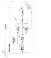
本実施形態の能動型防振装置1のうち異常検出処理部19を除く部分の構成について、図1を参照して説明する。なお、異常検出処理部19は後述する。図1は、能動型防振装置1のうち異常検出処理部19を除く部分の構成を示すブロック図である。本実施例の能動型防振装置1は、車両に搭載されたエンジンE/G(振動発生源)により発生される振動が車両の各部位に伝達されることを能動的に抑制するための装置である。なお、能動型防振装置1は、イグニッションスイッチがONすることにより起動可能な状態となる。この能動型防振装置1は、図1に示すように、周波数算出部11と、モード切替部12と、車両状態信号出力部13と、マップ制御部14と、適応制御部15と、駆動部16と、加振器17と、加速度センサ(Gセンサ)18とを備えている。
次に、適応制御部15の詳細構成について図2を参照して説明する。図2は、適応制御部15の構成を示すブロック図である。ここで、適応制御部15において採用する適応制御法は、遅延調和シンセサイザ最小平均自乗フィルタ(DXHS−LMS)を用いた制御法である。なお、適応制御部15は、上述したように、モード切替部12により適応制御モードに切り替えられた場合に実行される。
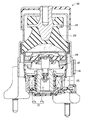
次に、加振器17及び加速度センサ18を備えた加振器付エンジンマウント20の詳細構成について図3を参照して説明する。図3は、加振器付エンジンマウント20の部分断面図を示す。
ここで、後述する異常検出処理部19により検出することができる加振器17の不動作異常について説明する。加振器17の不動作異常とは、加振器17が動作不可能な状態となる異常である。加振器17が動作不可能な状態とは、例えば、加振器17のコイル又はコイルに接続されている配線が断線した場合、加振器17のプランジャ17bがロックした場合、又は、加振器17のプランジャ17bを支持している加振板24が切断された場合などである。
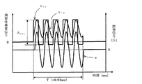
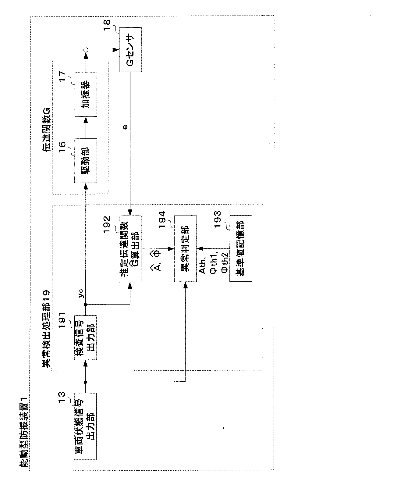
次に、能動型防振装置1の異常検出処理部19を含む部分の構成について、図4および図5を参照して説明する。図4は、能動型防振装置1の異常検出処理部19を含む部分の構成を示すブロック図である。図5は、周期性検査信号yc(yc1及びyc2)及び誤差信号eを示す図である。異常検出処理部19は、検査信号出力部191と、推定伝達関数算出部192と、基準値記憶部193と、異常判定部194とから構成される。
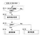
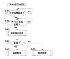
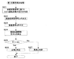
次に、上述した構成からなる能動型防振装置1の処理動作について、図6〜図10のフローチャートを参照して説明する。図6は、能動型防振装置1の第1のメイン処理を示すフローチャートである。図7は、能動型防振装置1の第2のメイン処理を示すフローチャートである。図8は、能動型防振装置1の第3のメイン処理を示すフローチャートである。図9は、能動型防振装置1の第1の異常検出処理を示すフローチャートである。図10は、能動型防振装置1の第2の異常検出処理を示すフローチャートである。なお、第1のメイン処理、第2のメイン処理及び第3のメイン処理は、何れかを選択して行われる。ただし、場合によっては、第1のメイン処理と第2のメイン処理、若しくは、第1のメイン処理と第3のメイン処理は、並行に実行するようにしてもよい。また、第1の異常検出処理と第2の異常検出処理とは、何れか一方を選択して行われる。
まずは、能動型防振装置1のメイン処理について説明する。まずは、第1のメイン処理について図6を参照して説明する。
次に、加振器17の異常検出処理について図9を参照して説明する。まずは、第1の異常検出処理について説明する。第1の異常検出処理は、図9に示すように、まず、車両状態信号出力部13からの車両状態信号に基づきアイドル運転状態であるか否かを判定する(ステップS21)。ここで、異常検出処理はイグニッションスイッチがONされた場合及びアイドル運転状態の場合に行う処理であるので、アイドル運転状態でない場合とは、イグニッションスイッチがONされた場合となる。
上記実施形態における能動型防振装置1は、マップ制御モードと適応制御モードとを切り替えるようにしたが、これに限られるものではない。例えば、マップ制御モードのみを適用してもよいし、適応制御モードのみを適用してもよい。すなわち、マップ制御モードのみの場合には、モード切替部12、適応制御部15及び加速度センサ18を含まない構成となる。この場合、駆動部16へ周期性制御信号yを出力するのは、マップ制御部14のみとなる。また、適応制御モードのみの場合には、モード切替部12及びマップ制御部14を含まない構成となる。この場合、駆動部16へ周期性制御信号yを出力するのは、適応制御部15のみとなる。
13:車両状態信号出力部、 14:マップ制御部(制御信号発生手段)、
15:適応制御部(制御信号発生手段)、 16:駆動部(駆動手段)、
17:加振器(電磁アクチュエータ)、 18:加速度センサ(駆動波形検査手段)、
20:加振器付エンジンマウント、 21:第1取付金具、 22:第2取付金具、
23:本体ゴム弾性体、 24:加振板、 25:ダイヤフラム、
151:適応フィルタ部、 152:推定伝達関数決定部、
153:フィルタ係数更新部、 191:検査信号出力部、
192:推定伝達関数算出部(推定伝達関数算出手段)、
193:基準値記憶部(基準値記憶手段)、 194:異常判定部(異常判定手段)
Claims (12)
- 電流通電量に応じた加振力を発生する電磁アクチュエータと、
車両の振動発生源から出力される周期性のパルス信号に基づき車両特定部位の振動を能動的に抑制させる周期性制御信号を発生する制御信号発生手段と、
前記周期性制御信号に基づき前記電流通電量を可変にして前記電磁アクチュエータを駆動する駆動手段と、
を備える能動型防振装置において、
さらに、前記電磁アクチュエータ及び前記駆動手段を含む伝達系の伝達関数の推定値である推定伝達関数を算出する推定伝達関数算出手段と、
前記推定伝達関数に基づき前記電磁アクチュエータの不動作異常を判定する異常判定手段と、
を備えることを特徴とする能動型防振装置。 - さらに、前記推定伝達関数のゲイン成分の基準ゲイン閾値を予め記憶する第1基準値記憶手段を備え、
前記異常判定手段は、前記推定伝達関数の前記ゲイン成分が前記基準ゲイン閾値より小さい場合に前記不動作異常と判定することを特徴とする請求項1記載の能動型防振装置。 - さらに、前記推定伝達関数の位相成分の基準位相範囲を予め記憶する第2基準値記憶手段を備え、
前記異常判定手段は、前記推定伝達関数の前記位相成分が前記基準位相範囲外である場合に前記不動作異常と判定することを特徴とする請求項1又は2に記載の能動型防振装置。 - 前記制御信号発生手段は、周波数が0〜30Hzの周期性信号からなる周期性検査信号を生成すると共に前記周期性検査信号を前記駆動手段に出力し、
さらに、前記周期性検査信号に基づき前記駆動手段により駆動される前記電磁アクチュエータの駆動波形を検出する駆動波形検出手段を備え、
前記推定伝達関数算出手段は、前記周期性検査信号及び前記駆動波形に基づき前記推定伝達関数を算出することを特徴とする請求項1〜3の何れか一項に記載の能動型防振装置。 - 前記周期性検査信号は、検査信号振幅が所定振幅以下であることを特徴とする請求項4に記載の能動型防振装置。
- 前記周期性検査信号は、検査信号時間が所定時間以内であることを特徴とする請求項4又は5に記載の能動型防振装置。
- 前記第1基準値記憶手段は、車両状態に応じて異なる複数の前記基準ゲイン閾値を記憶し、
前記異常判定手段は、前記推定伝達関数の前記ゲイン成分が前記推定伝達関数算出手段にて前記推定伝達関数が算出された際の車両状態に対応する前記基準ゲイン閾値より小さい場合に前記不動作異常と判定することを特徴とする請求項2記載の能動型防振装置。 - 前記第2基準値記憶手段は、車両状態に応じて異なる複数の前記基準位相範囲を記憶し、
前記異常判定手段は、前記推定伝達関数の前記位相成分が前記推定伝達関数算出手段にて前記推定伝達関数が算出された際の車両状態に対応する前記基準位相範囲外である場合に前記不動作異常と判定することを特徴とする請求項3記載の能動型防振装置。 - 前記推定伝達関数算出手段は、イグニッションスイッチがONされた後に前記推定伝達関数を算出することを特徴とする請求項1〜8の何れか一項に記載の能動型防振装置。
- 前記推定伝達関数算出手段は、イグニッションスイッチがONされた際に前記推定伝達関数を算出することを特徴とする請求項9記載の能動型防振装置。
- 前記推定伝達関数算出手段は、アイドル運転状態の際に前記推定伝達関数を算出することを特徴とする請求項9記載の能動型防振装置。
- 前記推定伝達関数算出手段は、イグニッションスイッチがONされてから所定時間経過した後であり且つアイドル運転状態の際に前記推定伝達関数を算出することを特徴とする請求項9記載の能動型防振装置。
Priority Applications (4)
| Application Number | Priority Date | Filing Date | Title |
|---|---|---|---|
| JP2005171178A JP4832808B2 (ja) | 2004-12-28 | 2005-06-10 | 能動型防振装置 |
| DE602005006083T DE602005006083T2 (de) | 2004-12-28 | 2005-12-27 | Aktiver Schwingungsdämpfer |
| US11/317,049 US7403367B2 (en) | 2004-12-28 | 2005-12-27 | Active vibration insulator |
| EP05028518A EP1677171B1 (en) | 2004-12-28 | 2005-12-27 | Active vibration insulator |
Applications Claiming Priority (3)
| Application Number | Priority Date | Filing Date | Title |
|---|---|---|---|
| JP2004381311 | 2004-12-28 | ||
| JP2004381311 | 2004-12-28 | ||
| JP2005171178A JP4832808B2 (ja) | 2004-12-28 | 2005-06-10 | 能動型防振装置 |
Publications (2)
| Publication Number | Publication Date |
|---|---|
| JP2006207794A true JP2006207794A (ja) | 2006-08-10 |
| JP4832808B2 JP4832808B2 (ja) | 2011-12-07 |
Family
ID=36046794
Family Applications (1)
| Application Number | Title | Priority Date | Filing Date |
|---|---|---|---|
| JP2005171178A Expired - Fee Related JP4832808B2 (ja) | 2004-12-28 | 2005-06-10 | 能動型防振装置 |
Country Status (4)
| Country | Link |
|---|---|
| US (1) | US7403367B2 (ja) |
| EP (1) | EP1677171B1 (ja) |
| JP (1) | JP4832808B2 (ja) |
| DE (1) | DE602005006083T2 (ja) |
Cited By (3)
| Publication number | Priority date | Publication date | Assignee | Title |
|---|---|---|---|---|
| JP2010121737A (ja) * | 2008-11-20 | 2010-06-03 | Nissan Motor Co Ltd | 車両伝達関数取得装置 |
| JP2010137769A (ja) * | 2008-12-12 | 2010-06-24 | Nissan Motor Co Ltd | 自己診断機能付騒音振動制御装置 |
| JP2015025480A (ja) * | 2013-07-25 | 2015-02-05 | 日産自動車株式会社 | 防振装置の制御装置 |
Families Citing this family (11)
| Publication number | Priority date | Publication date | Assignee | Title |
|---|---|---|---|---|
| US7513516B2 (en) * | 2005-08-23 | 2009-04-07 | Jri Development Group, Llc | Shock isolation cradle |
| JP4958154B2 (ja) * | 2006-11-29 | 2012-06-20 | 本田技研工業株式会社 | 自動二輪車 |
| EP2353911B1 (en) * | 2007-08-10 | 2012-09-19 | Honda Motor Co., Ltd. | Active vibration isolating support apparatus |
| CN102072276B (zh) * | 2010-12-30 | 2012-10-31 | 上海交通大学 | 电磁式船舶轴系纵向振动主动控制装置 |
| US20140039751A1 (en) * | 2012-08-06 | 2014-02-06 | Garmin Switzerland Gmbh | Cigarette lighter adapter for engine status monitoring |
| AU2014201238A1 (en) * | 2013-03-07 | 2014-09-25 | Telematics Data Systems Limited | Interface |
| US9126478B2 (en) * | 2013-05-28 | 2015-09-08 | GM Global Technology Operations LLC | Adaptive open loop control to reduce engine induced vibration and noise |
| CN105611443B (zh) | 2015-12-29 | 2019-07-19 | 歌尔股份有限公司 | 一种耳机的控制方法、控制系统和耳机 |
| CN105630021B (zh) * | 2015-12-31 | 2018-07-31 | 歌尔股份有限公司 | 一种智能终端的触觉振动控制系统和方法 |
| CN105511514B (zh) | 2015-12-31 | 2019-03-15 | 歌尔股份有限公司 | 一种智能终端的触觉振动控制系统和方法 |
| US10355670B1 (en) * | 2018-05-05 | 2019-07-16 | Baisheng Yu | Active suppression controller with tracking and correction for multiple time-varying fundamental frequencies |
Citations (8)
| Publication number | Priority date | Publication date | Assignee | Title |
|---|---|---|---|---|
| JPH0540481A (ja) * | 1991-08-08 | 1993-02-19 | Nissan Motor Co Ltd | 能動型騒音制御装置 |
| JPH06332471A (ja) * | 1993-05-24 | 1994-12-02 | Nissan Motor Co Ltd | 能動型騒音制御装置及び能動型振動制御装置 |
| JPH07158691A (ja) * | 1993-12-08 | 1995-06-20 | Mazda Motor Corp | 車両の振動低減装置 |
| JPH09317816A (ja) * | 1996-05-28 | 1997-12-12 | Nissan Motor Co Ltd | 能動型振動制御装置 |
| JPH11338505A (ja) * | 1998-05-27 | 1999-12-10 | Nissan Motor Co Ltd | 能動型振動制御装置及び能動型騒音制御装置 |
| JPH11338553A (ja) * | 1998-05-22 | 1999-12-10 | Nissan Motor Co Ltd | 能動型振動制御装置及び能動型騒音制御装置 |
| JP2000002294A (ja) * | 1998-06-18 | 2000-01-07 | Nissan Motor Co Ltd | 能動型騒音振動制御装置及び車両用能動型振動制御装置 |
| JP2000120767A (ja) * | 1998-10-13 | 2000-04-25 | Nissan Motor Co Ltd | 能動型騒音振動制御装置、車両用能動型振動制御装置及び能動型騒音振動制御方法 |
Family Cites Families (8)
| Publication number | Priority date | Publication date | Assignee | Title |
|---|---|---|---|---|
| JP3430699B2 (ja) | 1995-03-31 | 2003-07-28 | 日産自動車株式会社 | 制御型防振支持装置 |
| JPH08312714A (ja) * | 1995-05-23 | 1996-11-26 | Nissan Motor Co Ltd | 制御型防振支持装置 |
| JP3481046B2 (ja) * | 1996-06-13 | 2003-12-22 | 本田技研工業株式会社 | 車両のアクティブマウント用制御システムにおける故障診断方法及び装置 |
| JPH10196711A (ja) | 1997-01-13 | 1998-07-31 | Tokai Rubber Ind Ltd | アクティブマウント制御装置のフィルタ係数設定方法 |
| JP3451891B2 (ja) * | 1997-06-13 | 2003-09-29 | 日産自動車株式会社 | 能動型振動制御装置 |
| JP3767178B2 (ja) | 1998-06-29 | 2006-04-19 | 東海ゴム工業株式会社 | アクティブ制御装置 |
| JP2000020139A (ja) | 1998-06-29 | 2000-01-21 | Tokai Rubber Ind Ltd | アクティブ制御装置 |
| JP4284399B2 (ja) * | 2003-03-04 | 2009-06-24 | 本田技研工業株式会社 | エンジンの防振支持装置 |
-
2005
- 2005-06-10 JP JP2005171178A patent/JP4832808B2/ja not_active Expired - Fee Related
- 2005-12-27 DE DE602005006083T patent/DE602005006083T2/de not_active Expired - Lifetime
- 2005-12-27 EP EP05028518A patent/EP1677171B1/en not_active Expired - Lifetime
- 2005-12-27 US US11/317,049 patent/US7403367B2/en active Active
Patent Citations (8)
| Publication number | Priority date | Publication date | Assignee | Title |
|---|---|---|---|---|
| JPH0540481A (ja) * | 1991-08-08 | 1993-02-19 | Nissan Motor Co Ltd | 能動型騒音制御装置 |
| JPH06332471A (ja) * | 1993-05-24 | 1994-12-02 | Nissan Motor Co Ltd | 能動型騒音制御装置及び能動型振動制御装置 |
| JPH07158691A (ja) * | 1993-12-08 | 1995-06-20 | Mazda Motor Corp | 車両の振動低減装置 |
| JPH09317816A (ja) * | 1996-05-28 | 1997-12-12 | Nissan Motor Co Ltd | 能動型振動制御装置 |
| JPH11338553A (ja) * | 1998-05-22 | 1999-12-10 | Nissan Motor Co Ltd | 能動型振動制御装置及び能動型騒音制御装置 |
| JPH11338505A (ja) * | 1998-05-27 | 1999-12-10 | Nissan Motor Co Ltd | 能動型振動制御装置及び能動型騒音制御装置 |
| JP2000002294A (ja) * | 1998-06-18 | 2000-01-07 | Nissan Motor Co Ltd | 能動型騒音振動制御装置及び車両用能動型振動制御装置 |
| JP2000120767A (ja) * | 1998-10-13 | 2000-04-25 | Nissan Motor Co Ltd | 能動型騒音振動制御装置、車両用能動型振動制御装置及び能動型騒音振動制御方法 |
Cited By (3)
| Publication number | Priority date | Publication date | Assignee | Title |
|---|---|---|---|---|
| JP2010121737A (ja) * | 2008-11-20 | 2010-06-03 | Nissan Motor Co Ltd | 車両伝達関数取得装置 |
| JP2010137769A (ja) * | 2008-12-12 | 2010-06-24 | Nissan Motor Co Ltd | 自己診断機能付騒音振動制御装置 |
| JP2015025480A (ja) * | 2013-07-25 | 2015-02-05 | 日産自動車株式会社 | 防振装置の制御装置 |
Also Published As
| Publication number | Publication date |
|---|---|
| DE602005006083T2 (de) | 2009-06-18 |
| US7403367B2 (en) | 2008-07-22 |
| JP4832808B2 (ja) | 2011-12-07 |
| EP1677171A1 (en) | 2006-07-05 |
| DE602005006083D1 (de) | 2008-05-29 |
| EP1677171B1 (en) | 2008-04-16 |
| US20060139840A1 (en) | 2006-06-29 |
Similar Documents
| Publication | Publication Date | Title |
|---|---|---|
| JP4832808B2 (ja) | 能動型防振装置 | |
| JP3430699B2 (ja) | 制御型防振支持装置 | |
| US5905317A (en) | Vibration insulating device | |
| EP2023007B1 (en) | Damper for automobiles for reducing vibration of automobile body | |
| JPH11223238A (ja) | 能動型振動制御装置 | |
| JP2006349028A (ja) | 能動型防振装置 | |
| JP2006336736A (ja) | 能動型防振装置 | |
| JP4370933B2 (ja) | 能動型防振装置の振動制御方法及び振動制御装置 | |
| JP3593866B2 (ja) | 能動型騒音振動制御装置 | |
| JPH11338553A (ja) | 能動型振動制御装置及び能動型騒音制御装置 | |
| JP3551653B2 (ja) | 能動型騒音振動制御装置 | |
| JP2006349029A (ja) | 能動型防振装置 | |
| JPH10212994A (ja) | 車両用異常検出装置 | |
| JPH11338505A (ja) | 能動型振動制御装置及び能動型騒音制御装置 | |
| JPH04302729A (ja) | パワーユニット用マウント | |
| JPH09273589A (ja) | 振動騒音制御装置 | |
| JP3747619B2 (ja) | 能動型振動制御装置 | |
| JPH09317816A (ja) | 能動型振動制御装置 | |
| JP2013024323A (ja) | 車両用制振システム | |
| JPH05126200A (ja) | パワーユニツト用マウント | |
| JP2012140979A (ja) | 車両用能動型防振装置 | |
| JPH11201220A (ja) | 車輌振動騒音低減装置 | |
| JP2001001767A (ja) | 車両用能動型騒音振動制御装置 | |
| JP4830928B2 (ja) | 能動型防振装置 | |
| JP2004050938A (ja) | 能動型防振装置の制御方法 |
Legal Events
| Date | Code | Title | Description |
|---|---|---|---|
| A621 | Written request for application examination |
Free format text: JAPANESE INTERMEDIATE CODE: A621 Effective date: 20070911 |
|
| A977 | Report on retrieval |
Free format text: JAPANESE INTERMEDIATE CODE: A971007 Effective date: 20090806 |
|
| A131 | Notification of reasons for refusal |
Free format text: JAPANESE INTERMEDIATE CODE: A131 Effective date: 20090818 |
|
| A521 | Request for written amendment filed |
Free format text: JAPANESE INTERMEDIATE CODE: A523 Effective date: 20091015 |
|
| A131 | Notification of reasons for refusal |
Free format text: JAPANESE INTERMEDIATE CODE: A131 Effective date: 20100422 |
|
| A521 | Request for written amendment filed |
Free format text: JAPANESE INTERMEDIATE CODE: A523 Effective date: 20100611 |
|
| A02 | Decision of refusal |
Free format text: JAPANESE INTERMEDIATE CODE: A02 Effective date: 20101216 |
|
| A521 | Request for written amendment filed |
Free format text: JAPANESE INTERMEDIATE CODE: A523 Effective date: 20110315 |
|
| A521 | Request for written amendment filed |
Free format text: JAPANESE INTERMEDIATE CODE: A523 Effective date: 20110318 |
|
| A521 | Request for written amendment filed |
Free format text: JAPANESE INTERMEDIATE CODE: A523 Effective date: 20110315 |
|
| A911 | Transfer to examiner for re-examination before appeal (zenchi) |
Free format text: JAPANESE INTERMEDIATE CODE: A911 Effective date: 20110426 |
|
| TRDD | Decision of grant or rejection written | ||
| A01 | Written decision to grant a patent or to grant a registration (utility model) |
Free format text: JAPANESE INTERMEDIATE CODE: A01 Effective date: 20110906 |
|
| A01 | Written decision to grant a patent or to grant a registration (utility model) |
Free format text: JAPANESE INTERMEDIATE CODE: A01 |
|
| A61 | First payment of annual fees (during grant procedure) |
Free format text: JAPANESE INTERMEDIATE CODE: A61 Effective date: 20110921 |
|
| R150 | Certificate of patent or registration of utility model |
Ref document number: 4832808 Country of ref document: JP Free format text: JAPANESE INTERMEDIATE CODE: R150 Free format text: JAPANESE INTERMEDIATE CODE: R150 |
|
| FPAY | Renewal fee payment (event date is renewal date of database) |
Free format text: PAYMENT UNTIL: 20140930 Year of fee payment: 3 |
|
| S111 | Request for change of ownership or part of ownership |
Free format text: JAPANESE INTERMEDIATE CODE: R313117 |
|
| S533 | Written request for registration of change of name |
Free format text: JAPANESE INTERMEDIATE CODE: R313533 |
|
| R350 | Written notification of registration of transfer |
Free format text: JAPANESE INTERMEDIATE CODE: R350 |
|
| LAPS | Cancellation because of no payment of annual fees |