JP2006333473A - Signal generating apparatus and method - Google Patents
Signal generating apparatus and method Download PDFInfo
- Publication number
- JP2006333473A JP2006333473A JP2006141916A JP2006141916A JP2006333473A JP 2006333473 A JP2006333473 A JP 2006333473A JP 2006141916 A JP2006141916 A JP 2006141916A JP 2006141916 A JP2006141916 A JP 2006141916A JP 2006333473 A JP2006333473 A JP 2006333473A
- Authority
- JP
- Japan
- Prior art keywords
- signal
- counter
- value
- register
- generator
- Prior art date
- Legal status (The legal status is an assumption and is not a legal conclusion. Google has not performed a legal analysis and makes no representation as to the accuracy of the status listed.)
- Pending
Links
Images


Classifications
-
- G—PHYSICS
- G06—COMPUTING OR CALCULATING; COUNTING
- G06F—ELECTRIC DIGITAL DATA PROCESSING
- G06F1/00—Details not covered by groups G06F3/00 - G06F13/00 and G06F21/00
- G06F1/02—Digital function generators
- G06F1/03—Digital function generators working, at least partly, by table look-up
- G06F1/0321—Waveform generators, i.e. devices for generating periodical functions of time, e.g. direct digital synthesizers
- G06F1/0328—Waveform generators, i.e. devices for generating periodical functions of time, e.g. direct digital synthesizers in which the phase increment is adjustable, e.g. by using an adder-accumulator
-
- G—PHYSICS
- G06—COMPUTING OR CALCULATING; COUNTING
- G06F—ELECTRIC DIGITAL DATA PROCESSING
- G06F1/00—Details not covered by groups G06F3/00 - G06F13/00 and G06F21/00
- G06F1/02—Digital function generators
- G06F1/022—Waveform generators, i.e. devices for generating periodical functions of time, e.g. direct digital synthesizers
-
- H—ELECTRICITY
- H03—ELECTRONIC CIRCUITRY
- H03K—PULSE TECHNIQUE
- H03K5/00—Manipulating of pulses not covered by one of the other main groups of this subclass
- H03K5/01—Shaping pulses
- H03K5/04—Shaping pulses by increasing duration; by decreasing duration
- H03K5/05—Shaping pulses by increasing duration; by decreasing duration by the use of clock signals or other time reference signals
Landscapes
- Engineering & Computer Science (AREA)
- Theoretical Computer Science (AREA)
- Physics & Mathematics (AREA)
- General Engineering & Computer Science (AREA)
- General Physics & Mathematics (AREA)
- Nonlinear Science (AREA)
- Manipulation Of Pulses (AREA)
- Analogue/Digital Conversion (AREA)
- Pulse Circuits (AREA)
Abstract
【課題】基準クロック信号に従ってデジタル値のシーケンスを生成することのできる信号発生器を提供する。
【解決手段】本発明の一実施形態によれば、基準クロック信号に従ってデジタル値のシーケンスを生成する信号発生器3が提供される。この信号発生器3は、インクリメント信号INC及びオフセット信号Φ1、Φ2を受け取る少なくとも1つの入力端子32、33、34と、オフセット信号Φとインクリメント信号INCに基づいてカウンタ開始値を決定するようになっている開始値回路302と、開始値に設定されるようになっており、基準クロック信号の各サイクルにおいて、規定の値が達成されるまで、カウンタの位置をインクリメント信号INCに従って新しい値に変更するようになっているカウンタと、カウンタ値を出力する出力端子とを備える。
【選択図】図3AA signal generator is provided that can generate a sequence of digital values according to a reference clock signal.
According to one embodiment of the present invention, a signal generator is provided for generating a sequence of digital values according to a reference clock signal. The signal generator 3 determines a counter start value based on at least one input terminal 32, 33, 34 that receives the increment signal INC and the offset signals Φ1, Φ2, and the offset signal Φ and the increment signal INC. The start value circuit 302 is set to a start value, and in each cycle of the reference clock signal, the counter position is changed to a new value according to the increment signal INC until a specified value is achieved. And a counter for outputting the counter value.
[Selection] Figure 3A
Description
本発明はデジタル信号生成に関する。 The present invention relates to digital signal generation.
任意の信号生成において、パルスは、個々の連続するデジタル信号のシーケンスとして理解することができる。パルス信号の時間的な振る舞いは、異なるパラメータによって記述することができる。パルス周期は、2つの連続するパルス信号間の期間を規定する。さらなるパラメータは、パルス信号の遅延及びパルス幅を規定する。 In any signal generation, a pulse can be understood as a sequence of individual successive digital signals. The temporal behavior of the pulse signal can be described by different parameters. The pulse period defines the period between two successive pulse signals. Further parameters define the delay and pulse width of the pulse signal.
アナログ回路構成を使用するデジタルパルスパターン発生器は、従来技術により既知である。先に規定したパラメータに従ってパルスパターンを生成するために、個々の発振器回路が設けられるであろう。こうしたパルス発生器の例は、出願人アジレント・テクノロジーズ(Agilent Technologies)のパルスパターン発生器のアジレント81100ファミリーである。 Digital pulse pattern generators using analog circuitry are known from the prior art. Individual oscillator circuits will be provided to generate the pulse pattern according to the parameters defined above. An example of such a pulse generator is the Agilent 81100 family of pulse pattern generators from Applicants Agilent Technologies.
改良型信号発生器を提供することが本発明の目的である。 It is an object of the present invention to provide an improved signal generator.
この目的は、独立請求項で規定される本発明によって達成される。好ましい実施形態は、従属請求項の主題である。 This object is achieved by the present invention as defined in the independent claims. Preferred embodiments are the subject matter of the dependent claims.
本発明の一実施形態によるデジタル値のシーケンスを生成する発生器は、基準クロックに依存してカウンタの位置を与えるようになっているカウンタを備える。より詳細には、カウンタは、カウンタの位置を基準クロックサイクル毎に与えるようになっている。本発明の実施形態によるデジタルエッジ発生器は、開始信号、インクリメント信号(インクリメントワードとさらに呼ばれる)、及びオフセット信号(オフセットワードとさらに呼ばれる)をそれぞれ受け取る。オフセットワードは、時間上のエッジの開始点の遅延に対応する。デジタルエッジ発生器は、開始信号の検出によって、オフセットワードとインクリメントワードの掛け算から導出される開始位置にカウンタの位置を設定するようになっている。デジタルエッジ発生器はまた、クロックサイクル毎にインクリメントワードから導出される新しい位置にカウンタの位置を設定する。 A generator for generating a sequence of digital values according to an embodiment of the invention comprises a counter adapted to provide a counter position depending on a reference clock. More specifically, the counter provides the position of the counter every reference clock cycle. A digital edge generator according to embodiments of the present invention receives a start signal, an increment signal (further referred to as an increment word), and an offset signal (further referred to as an offset word), respectively. The offset word corresponds to the delay of the start point of the edge over time. The digital edge generator sets the counter position to the start position derived from the multiplication of the offset word and the increment word by detecting the start signal. The digital edge generator also sets the counter position to a new position derived from the increment word every clock cycle.
開始信号の検出による、且つ、オフセットワードに依存する開始位置の設定は、より柔軟なタイミング設定を可能にする。より詳細には、オフセットワードは、立上がりエッジ又は立下がりエッジが、連続する基準クロックサイクルの間で開始し得ることを考慮する。エッジの歪(変形)をもたらす、さらなる望ましくない次の基準クロックサイクルまでの開始遅延は発生しないであろう。エッジの傾斜は、インクリメントワードによって与えられ、インクリメントワードは、立上がりエッジの場合に正値を、立下がりエッジの場合に負値を含むことが留意されるであろう。一実施形態では、開始位置は、オフセットワードとインクリメントワードから導出される。この実施形態では、エッジ発生器は、立上がりエッジ又は立下がりエッジを特徴付ける、デジタル信号のシーケンス、より詳細には、デジタル値のシーケンスを生成するようになっている。コンデンサ等のアナログ回路及びアナログ回路の較正は必要ない。 Setting the start position by detecting the start signal and depending on the offset word enables more flexible timing setting. More specifically, the offset word takes into account that a rising or falling edge can begin between successive reference clock cycles. There will be no start delay until the next undesired next reference clock cycle, which results in edge distortion. It will be noted that the slope of the edge is given by the increment word, which contains a positive value for the rising edge and a negative value for the falling edge. In one embodiment, the starting position is derived from the offset word and the increment word. In this embodiment, the edge generator is adapted to generate a sequence of digital signals, more particularly a sequence of digital values, that characterizes rising or falling edges. Calibration of analog circuits such as capacitors and analog circuits is not necessary.
別の実施形態において、カウンタはレジスタ及び加算要素を備え、加算要素は、エッジ発生器の第1入力端子及びレジスタの出力に接続される。カウンタの値に対応するレジスタの値は、フィードバックされ、インクリメントワードと加算され、新しい値としてレジスタに記憶される。基準クロックサイクル毎に、レジスタは、その値を増減する。別の実施形態では、スイッチが、加算要素とレジスタの入力の間に結合される。スイッチはまた、開始位置をレジスタに記憶するために、オフセットワード用の第2入力端子に結合される。 In another embodiment, the counter comprises a register and an addition element, which is connected to the first input terminal of the edge generator and the output of the register. The register value corresponding to the counter value is fed back, added to the increment word, and stored in the register as a new value. Each reference clock cycle causes the register to increase or decrease its value. In another embodiment, a switch is coupled between the summing element and the input of the register. The switch is also coupled to the second input terminal for the offset word for storing the starting position in the register.
さらなる実施形態において、出力はメモリルックアップテーブルに結合され、メモリルックアップテーブルは、カウンタの出力から導出されたデジタル値を生成するようになっている。メモリルックアップテーブルは、さらなる歪を使用するか、又は、スプリアスを抑制する場合に有利である。別法として、エッジ発生器の出力は、デジタル・アナログ変換器に結合される。さらに別の実施形態では、カウンタの出力はスイッチに結合される。一定のデジタル値が、スイッチの第2入力に供給される。スイッチは、開始信号の検出によって、且つカウンタの位置に依存してその位置を切り換える。 In a further embodiment, the output is coupled to a memory lookup table that generates a digital value derived from the output of the counter. Memory look-up tables are advantageous when using additional distortions or suppressing spurious. Alternatively, the output of the edge generator is coupled to a digital to analog converter. In yet another embodiment, the counter output is coupled to a switch. A constant digital value is supplied to the second input of the switch. The switch switches its position by detecting the start signal and depending on the position of the counter.
本発明の一実施形態による制御式パルスパターン発生器は、デジタル周波数合成を使用する。生成プロセスのために、実施形態は、パルス周期、パルス幅、立上がり時間及び立下がり時間を含む、パルスを規定するタイミングパラメータの、柔軟且つ個々の設定を実施する。パルス傾斜のデジタル生成を含む全てのタイミングパラメータは、1つの安定した高速クロックから導出される。今後、立上がり時間及び立下がり時間は、本発明によるデジタルエッジ発生器を使用して互いに独立に選択することができる。アナログ回路の複雑な較正は全く必要でない。特に、制御式パルスパターン発生器は、開始信号及び第1オフセットワードを生成するようになっている周期カウンタを備える。開始信号及び第1オフセットワードは、高速安定基準クロック及び所与の(pre-given)パルス周期から導出される。周期カウンタの出力端子は、第1デジタルエッジ発生器に結合される。第1デジタルエッジ発生器は、開始信号及び第1オフセットワードに対して立上がりエッジを生成するようになっている。さらなる幅カウンタもまた、周期カウンタに結合される。幅カウンタは、停止信号、並びに、所与のパルス幅、基準クロック、及び開始信号に対する第1オフセットワードから導出される第2オフセットワードを生成するようになっている。最後に、幅カウンタに結合する第2デジタルエッジ発生器は、停止信号及び第2オフセットワードに対する立下がりエッジを生成するようになっている。 A controlled pulse pattern generator according to one embodiment of the present invention uses digital frequency synthesis. For the generation process, embodiments implement flexible and individual settings of timing parameters that define the pulse, including pulse period, pulse width, rise time and fall time. All timing parameters, including digital generation of pulse ramps, are derived from one stable high speed clock. From now on, the rise time and fall time can be selected independently of each other using the digital edge generator according to the present invention. No complicated calibration of the analog circuit is necessary. In particular, the controlled pulse pattern generator comprises a period counter adapted to generate a start signal and a first offset word. The start signal and the first offset word are derived from a fast stable reference clock and a given pre-given pulse period. The output terminal of the period counter is coupled to the first digital edge generator. The first digital edge generator is adapted to generate a rising edge with respect to the start signal and the first offset word. An additional width counter is also coupled to the period counter. The width counter is adapted to generate a stop signal and a second offset word derived from the first offset word for a given pulse width, reference clock and start signal. Finally, a second digital edge generator coupled to the width counter is adapted to generate a falling edge for the stop signal and the second offset word.
周期カウンタ及び幅カウンタは、基準クロック、パルス周期、及びパルス幅それぞれに対して、可能な位相オフセットワードを考慮する。そのため、パルス周期及びパルス幅がそれぞれ、基準クロックサイクルの非整数倍を含む場合、位相オフセットワードが生成されることになり、位相オフセットワードは、連続する基準クロックサイクル間の遅延に対応する。本発明による実施形態は、パルス周期及びパルス幅を基準クロックと独立に設定すると共に、対応するパルスパターンを生成するようになっている。さらに、エッジ発生器は、互いに独立であり、生成のために、傾斜の任意の設定が可能である。本発明の一実施形態によるパルスパターン発生器は、ただ1つの安定した基準クロックを使用する。発振器は同調される必要がないため、パルスタイミングパラメータの変更は高速で行われる。 The period counter and width counter consider possible phase offset words for each of the reference clock, pulse period, and pulse width. Thus, if the pulse period and pulse width each include a non-integer multiple of the reference clock cycle, a phase offset word will be generated, which corresponds to the delay between successive reference clock cycles. The embodiment according to the present invention sets the pulse period and the pulse width independently of the reference clock and generates a corresponding pulse pattern. Furthermore, the edge generators are independent of each other and any setting of slope is possible for generation. The pulse pattern generator according to an embodiment of the present invention uses only one stable reference clock. Since the oscillator does not need to be tuned, changing the pulse timing parameter is done at high speed.
本発明の一実施形態では、スイッチングユニットが提供される。スイッチングユニットは、その入力が、それぞれの第1エッジ発生器及び第2エッジ発生器のそれぞれの出力に結合される。スイッチングユニットは、開始信号及び停止信号に対してスイッチングユニットの入力の一方をスイッチングユニットの出力に切り換えるようになっている。さらに、スイッチングユニットは、開始信号が供給される場合に、第1エッジ発生器の出力をスイッチングユニットの出力に結合し、停止信号が供給される場合に、第2エッジ発生器の出力をスイッチングユニットの出力に結合するようになっている。開始信号及び停止信号の生成によって、対応するエッジ発生器の出力は、次に、開始信号及び停止信号に対応して、スイッチングユニットによって制御式パルスパターン発生器の出力を通して供給される。好ましくは、スイッチングユニットの出力は、デジタル・アナログ変換器に結合される。 In one embodiment of the present invention, a switching unit is provided. The switching unit has its input coupled to the respective outputs of the respective first and second edge generators. The switching unit switches one input of the switching unit to the output of the switching unit in response to the start signal and the stop signal. Further, the switching unit couples the output of the first edge generator to the output of the switching unit when a start signal is supplied, and the output of the second edge generator when the stop signal is supplied. It is designed to be coupled to the output of. By generating the start signal and the stop signal, the corresponding edge generator output is then supplied by the switching unit through the output of the controlled pulse pattern generator in response to the start signal and the stop signal. Preferably, the output of the switching unit is coupled to a digital to analog converter.
さらなる一実施形態では、周期カウンタは、第1レジスタと、第1レジスタに結合するオーバフロー検出デバイスとを備え、第1レジスタのオーバフローを検出するようになっている。周期カウンタは、オーバフローの検出によって開始信号を生成するようになっている。さらに、第1オフセットワードは、第1レジスタのオーバフロー値から導出され、オーバフローの検出によっても生成される。好ましい一実施形態では、パルス周期は、第1レジスタの長さ及びインクリメントワードから導出される。特に、レジスタの値は、第1レジスタの長さに達するまで基準クロックサイクル毎にインクリメントワードだけ増加する。次のインクリメントによって、オーバフロー検出デバイスは、レジスタのオーバフローを検出し、レジスタのオーバフロー値も導出することになる。オーバフロー値は、遅延に対応し、インクリメントワードより小さい値を含む。 In a further embodiment, the period counter comprises a first register and an overflow detection device coupled to the first register for detecting an overflow of the first register. The period counter generates a start signal upon detection of overflow. Furthermore, the first offset word is derived from the overflow value of the first register and is also generated by detecting overflow. In a preferred embodiment, the pulse period is derived from the length of the first register and the increment word. In particular, the value of the register increases by increment words every reference clock cycle until the length of the first register is reached. With the next increment, the overflow detection device will detect a register overflow and also derive a register overflow value. The overflow value corresponds to the delay and includes a value smaller than the increment word.
さらなる一実施形態では、幅カウンタは、第2レジスタと、第2レジスタに結合し、且つ、オーバフローを検出するようになっているオーバフロー検出デバイスとを備える。幅カウンタは、開始信号の検出によって、停止信号及び第2オフセットワードを生成するようになっている。第2オフセットワードは、第2レジスタのオーバフロー値から導出される。好ましい一実施形態では、パルス幅は、少なくとも第2レジスタの長さ及びインクリメントワードから導出される。 In a further embodiment, the width counter comprises a second register and an overflow detection device coupled to the second register and adapted to detect overflow. The width counter generates a stop signal and a second offset word by detecting the start signal. The second offset word is derived from the overflow value of the second register. In a preferred embodiment, the pulse width is derived from at least the length of the second register and the increment word.
安定した基準クロックとパルス周期の間の可能な位相オフセットが考慮されなければならないため、幅カウンタは、第1オフセットワードから導出される開始位置を第2レジスタに保存する手段を備える。 Since the possible phase offset between the stable reference clock and the pulse period has to be taken into account, the width counter comprises means for storing the starting position derived from the first offset word in the second register.
本発明の一実施形態では、第1レジスタ及び第2レジスタは、少なくとも48ビットのレジスタ長、より詳細には、64ビットのレジスタ長を備える。同様に、他のレジスタ長、及び周期カウンタ及び幅カウンタの第1レジスタ及び第2レジスタについて異なるレジスタ長を使用することが可能である。たとえば、第1レジスタは、32ビット、36ビット、又は72ビットの長さを含むであろう。安定した基準クロックサイクルと共にレジスタ長は、それぞれ、パルス周期及びパルス幅の最大長を規定する。 In one embodiment of the present invention, the first register and the second register have a register length of at least 48 bits, more specifically a register length of 64 bits. Similarly, different register lengths and different register lengths can be used for the first and second registers of the period and width counters. For example, the first register may include a length of 32 bits, 36 bits, or 72 bits. The register length along with the stable reference clock cycle defines the maximum length of the pulse period and pulse width, respectively.
本発明のパルスパターン発生器によって生成されるパルスの傾斜は、信号内のスプリアスを抑圧するか、又は、防止するために、変形させることが必要になるかもしれない。したがって、本発明の一実施形態によるパルスパターン発生器は、第1エッジ発生器及び第2エッジ発生器の出力に結合するメモリテーブルを備える。メモリテーブルは、出力値を含み、第1エッジ発生器及び第2エッジ発生器のデジタル出力から導出されるデジタル値を生成するようになっている。好ましくは、メモリテーブルは、メモリルックアップテーブルとして構成され、メモリルックアップテーブルは、エッジ発生器によって生成される出力値を平滑化又は変更するのに使用することができる。出力値をスケーリングするか、又は、変形させることが可能である。 The slope of the pulses generated by the pulse pattern generator of the present invention may need to be distorted to suppress or prevent spurious in the signal. Accordingly, a pulse pattern generator according to an embodiment of the present invention comprises a memory table coupled to the outputs of the first edge generator and the second edge generator. The memory table includes output values and generates digital values derived from the digital outputs of the first edge generator and the second edge generator. Preferably, the memory table is configured as a memory lookup table, which can be used to smooth or modify the output values generated by the edge generator. The output value can be scaled or transformed.
さらなる一実施形態では、第1エッジ発生器及び第2エッジ発生器の出力は、デジタル・アナログ変換のために、デジタル・アナログ変換器の入力に結合される。一実施形態では、パルスパターン発生器は、メモリルックアップテーブルの出力に結合するデジタル・アナログ変換器を備える。本発明のこの実施形態によるパルスパターン発生器の出力は、デジタル的に生成されるか、又は、別法として、完全にデジタル的に生成される、アナログパルスパターンである。 In a further embodiment, the outputs of the first edge generator and the second edge generator are coupled to the input of a digital to analog converter for digital to analog conversion. In one embodiment, the pulse pattern generator comprises a digital to analog converter that couples to the output of the memory lookup table. The output of the pulse pattern generator according to this embodiment of the present invention is an analog pulse pattern that is generated digitally or, alternatively, is generated completely digitally.
先に述べたように、パルスパターンは、パルス周期、パルス幅、及びパルス遅延によって規定することができる。より柔軟性のある方法でパルスパターンを生成するために、本発明による方法は直接周波数合成を使用する。本方法は、第1ステップにて、安定した基準クロックを提供する。同様に、パルス周期及びパルス幅が規定されなければならない。信号は、開始信号及び第1オフセットワードに対して立上がりエッジを生成することによって生成される。開始信号及び第1オフセットワードは、パルス周期及び安定した基準クロックから導出される。第1オフセットワードは、パルス周期が、基準クロックサイクルの非整数倍であることを考慮する。第1オフセットワードは、後に生成されるパルスのあらゆる遅延を修正するのに使用される。さらに、第1オフセットワードは、立上がりエッジがデジタル的に生成される時、開始位置を設定することによってエッジ生成を修正する。 As described above, the pulse pattern can be defined by a pulse period, a pulse width, and a pulse delay. In order to generate the pulse pattern in a more flexible way, the method according to the invention uses direct frequency synthesis. The method provides a stable reference clock in the first step. Similarly, the pulse period and pulse width must be specified. The signal is generated by generating a rising edge with respect to the start signal and the first offset word. The start signal and the first offset word are derived from the pulse period and a stable reference clock. The first offset word takes into account that the pulse period is a non-integer multiple of the reference clock cycle. The first offset word is used to correct any delays in the subsequently generated pulses. In addition, the first offset word modifies edge generation by setting the starting position when the rising edge is digitally generated.
立上がりエッジは、その後、出力される。さらに、立下がりエッジを有する信号は、停止信号及び第2オフセットワードに対して生成される。停止信号及び第2オフセットワードは、パルス幅、安定した基準クロック、開始信号、及び第1オフセットワードから導出される。第2オフセットワードは、パルス幅が、基準クロックサイクルの非整数倍であり得ることを考慮する。立下がりエッジは、その後、出力される。 The rising edge is then output. In addition, a signal having a falling edge is generated for the stop signal and the second offset word. The stop signal and the second offset word are derived from the pulse width, the stable reference clock, the start signal, and the first offset word. The second offset word takes into account that the pulse width may be a non-integer multiple of the reference clock cycle. The falling edge is then output.
本発明の一実施形態による方法は、周波数安定基準クロックを有する完全デジタル合成式発生器で使用されるであろう。一実施形態では、立上がりエッジを有する信号を生成するステップは、カウンタをインクリメントワードだけインクリメントすることも含む。インクリメントワードは、パルス周期に対応する。開始信号の生成は、カウンタのオーバフローを検出することによって起こる。第1オフセットワードは、カウンタのオーバフロー値から導出される。オフセットワードはエッジの開始と基準クロックサイクルの間の時間遅延に対応する。好ましくは、立上がりエッジカウンタは、以前に導出された第1オフセットワードから導出された開始位置に設定される。エッジカウンタは、その後、生成されるパルス信号の立上がりエッジ傾斜に対応するインクリメントワードだけインクリメントされる。立上がりエッジカウンタの位置は、その後、安定した基準クロックに対して出力される。同じ方法で、立下がりエッジを有する信号が生成される。 The method according to one embodiment of the invention will be used with a fully digital synthesis generator having a frequency stable reference clock. In one embodiment, generating a signal having a rising edge also includes incrementing a counter by an increment word. The increment word corresponds to the pulse period. Generation of the start signal occurs by detecting a counter overflow. The first offset word is derived from the counter overflow value. The offset word corresponds to the time delay between the start of the edge and the reference clock cycle. Preferably, the rising edge counter is set to a starting position derived from a previously derived first offset word. The edge counter is then incremented by an increment word corresponding to the rising edge slope of the generated pulse signal. The position of the rising edge counter is then output relative to a stable reference clock. In the same way, a signal with a falling edge is generated.
本発明の一実施形態では、パルスを生成する方法は、開始信号及び第1オフセットワードに対して立上がりエッジを有する信号を生成するステップを含んでもよく、開始信号及び第1オフセットワードは、生成されるパルスのパルス周期及び安定した基準クロックから導出される。エッジが出力される。その後、停止信号及び第2オフセットワードに対する立下がりエッジを有する信号が生成され、停止信号及び第2オフセットワードは、パルス幅、安定した基準クロック、開始信号、及び第1オフセットワードから導出される。立下がりエッジを有する信号が出力される。 In one embodiment of the present invention, the method for generating a pulse may include generating a signal having a rising edge with respect to the start signal and the first offset word, wherein the start signal and the first offset word are generated. Derived from the pulse period and the stable reference clock. Edge is output. Thereafter, a signal having a falling edge with respect to the stop signal and the second offset word is generated, and the stop signal and the second offset word are derived from the pulse width, the stable reference clock, the start signal, and the first offset word. A signal having a falling edge is output.
本発明のさらなる一実施形態では、安定した基準クロックが提供され、パルス周期を表す信号及びパルス幅を表す信号が受け取られる。両方の信号を受け取ることは、互いに独立なパラメータの設定を可能にする。本発明のさらなる一実施形態では、パルス信号は、それぞれ、インクリメント信号又はインクリメントワードだけカウンタをインクリメントすることによって生成され、インクリメントワードはパルス幅に対応する。カウンタのオーバフローの検出によって、開始信号及びオーバフロー値から導出される第1オフセットワードが生成される。開始信号及び位相オフセットワードは、立上がりエッジの生成に使用される。 In a further embodiment of the invention, a stable reference clock is provided and a signal representing the pulse period and a signal representing the pulse width are received. Receiving both signals allows the setting of parameters independent of each other. In a further embodiment of the invention, the pulse signal is generated by incrementing the counter by an increment signal or increment word, respectively, where the increment word corresponds to the pulse width. Detection of counter overflow generates a first offset word derived from the start signal and the overflow value. The start signal and the phase offset word are used to generate a rising edge.
本発明のさらに別の実施形態では、立上がりエッジを生成することは、立上がりエッジカウンタを、第1オフセットワードから導出される開始位置に設定するステップを含む。立上がりエッジ傾斜は、立上がりエッジカウンタを基準クロックサイクル毎にインクリメントし、立上がりエッジカウンタを基準クロックサイクル毎に出力させる立上がりインクリメント信号又は立上がりインクリメントワードによって規定される。 In yet another embodiment of the present invention, generating the rising edge includes setting the rising edge counter to a starting position derived from the first offset word. The rising edge slope is defined by a rising increment signal or rising increment word that increments the rising edge counter every reference clock cycle and causes the rising edge counter to output every reference clock cycle.
パルス幅を、パルス幅に対応するさらなるワードから導出することができることに気付くかもしれない。ワードは、幅カウンタをインクリメントし、幅カウンタは、一実施形態では、それぞれ、第1オフセット信号又は第1オフセットワードから導出される開始値に設定される。幅カウンタは、基準クロックサイクル毎に、パルス幅に対応するワードだけインクリメントされる。幅カウンタのオーバフローの検出によって、停止信号が生成され、幅カウンタのオーバフロー値が導出され、第2オフセット信号又は第2オフセットワードを規定する。停止信号及び第2オフセットワードを使用することによって、立上がりエッジの生成と同じ方法で立下がりエッジが生成される。もちろん、立下がりエッジカウンタは、ここでは、基準クロックサイクル毎にデクリメントされる。 You may find that the pulse width can be derived from additional words corresponding to the pulse width. The word increments the width counter, which in one embodiment is set to a starting value derived from the first offset signal or the first offset word, respectively. The width counter is incremented by a word corresponding to the pulse width every reference clock cycle. Upon detection of the width counter overflow, a stop signal is generated and the width counter overflow value is derived to define a second offset signal or second offset word. By using the stop signal and the second offset word, the falling edge is generated in the same way as the rising edge is generated. Of course, the falling edge counter is decremented here every reference clock cycle.
本発明の方法の種々の実施形態は、デジタルパルスに相当するデジタル信号のシーケンスを生成するための、高速で柔軟性のある方法を提供する。デジタルパルスは、アナログパルスに容易に変換することができる。異なるワード及びカウンタは、パルスのタイミングパラメータの独立した設定を可能にする。さらに、全てのタイミングパラメータは、オフセット信号を使用することによって、全てのタイミングパラメータが基準クロックサイクルの非整数倍であり得ることを考慮する。 Various embodiments of the method of the present invention provide a fast and flexible method for generating a sequence of digital signals corresponding to digital pulses. Digital pulses can be easily converted to analog pulses. Different words and counters allow independent setting of pulse timing parameters. Further, all timing parameters take into account that by using an offset signal, all timing parameters can be non-integer multiples of the reference clock cycle.
本発明の方法は、特定用途向け回路、フィールドプログラマブルゲートアレイ、デジタル信号プロセッサ、又はマイクロプロセッサ等のハードウェア部品に限定されない。同様に、データキャリアに記憶されるソフトウェアプログラム又はソフトウェア製品は、データ処理システム上で実行される時に本方法を実行するようになっていることができる。これは、完全にソフトウェアによるパルスパターン信号の柔軟性のある生成を可能にする。 The method of the present invention is not limited to hardware components such as application specific circuits, field programmable gate arrays, digital signal processors, or microprocessors. Similarly, a software program or software product stored on a data carrier can be adapted to perform the method when executed on a data processing system. This allows a flexible generation of the pulse pattern signal entirely by software.
本発明の他の目的及び多くの利点は、添付図面と共に考えられる以下の説明を参照することによって、容易に認識され、よりよく理解されるであろう。 Other objects and many advantages of the present invention will be readily appreciated and better understood by reference to the following description taken in conjunction with the accompanying drawings.
図10は、立上がり時間TRを有する立上がりエッジ及び立下がり時間TFを有する立下がりエッジを有する例示的なパルスを示す。立上がりエッジの終わりと立下がりエッジの始めの間の時間THは、パルスのハイ状態とみなされる。立上がり時間TRとパルスのハイ状態の和は、パルス幅TWと規定することにする。2つの連続するパルス間の総期間TPは、パルス幅TW、立下がり時間TF、及びパルスのロー状態ともみなすことができる遅延時間TDによって与えられる。 FIG. 10 shows an exemplary pulse having a rising edge with a rising time T R and a falling edge with a falling time T F. Time T H between the beginning end and the falling edge of the rising edge is considered a high state of the pulse. The sum of the high state of the rising time T R and the pulse is to be defined as the pulse width T W. The total period T P between two consecutive pulses is given by the pulse width T W , the fall time T F , and the delay time T D which can also be regarded as the low state of the pulse.
位相累算技法を使用する従来の方法は、直接デジタル周波数合成を使用する図11に示される。出力制御ワードWは、αの一定増分で連続して増加する。制御ワードWは、レジスタRによって出力され、レジスタRは、レジスタの内部位置をインクリメントするカウンタを表す。出力制御ワードWは、ルックアップテーブル又はアナログ・デジタル変換器への引数として使用される。周波数は、位相の偏移であるとして規定されるため、デジタル・アナログ変換器の出力は、インクリメント値αによって決定される一定周波数のアナログ信号である。 A conventional method using phase accumulation techniques is shown in FIG. 11 using direct digital frequency synthesis. The output control word W increases continuously with a constant increment of α. The control word W is output by the register R, which represents a counter that increments the internal position of the register. The output control word W is used as an argument to a look-up table or an analog to digital converter. Since the frequency is defined as a phase shift, the output of the digital-to-analog converter is a constant frequency analog signal determined by the increment value α.
図3は、本発明によるデジタル立上がりエッジ発生器の一実施形態を示す。対応する立下がりエッジ発生器は、より詳細に以下で説明されるであろう。 FIG. 3 illustrates one embodiment of a digital rising edge generator according to the present invention. A corresponding falling edge generator will be described in more detail below.
デジタル立上がりエッジ発生器は、特定の長さ、たとえば、48ビットのレジスタ38を有するカウンタ37を備える。32、36、54、又は24のような他のレジスタ長も使用することができる。カウンタ37は、図11による直接デジタル周波数合成ループと同じである。レジスタ38の出力Xは、カウンタの位置に対応する。出力Xは、端子31に供給されるが、出力XをインクリメントワードINCに加算する加算要素36にもフィードバックされる。このインクリメントワードは、立上がりエッジの傾斜を規定する。和X+INCは、レジスタ38の古い値と置き換わる。立上がりエッジ発生器3は、インクリメントワードINC用の入力端子34を備える。立上がりエッジ発生器3は、さらに、周期カウンタデバイス2によって供給される開始信号用の入力端子33及び基準クロックCLK用の端子35を備える。入力端子33及び35は、カウンタ37のレジスタ38に結合される。動作時、レジスタは、クロックサイクルCLK毎にレジスタの値を出力する。さらに、レジスタの値は、基準クロックサイクルCLK毎に、インクリメントワードINCだけ増加する。さらに、レジスタ38は、第1オフセットワードΦ1用の端子32に結合される。オフセットワードΦ1は、レジスタ38に開始値として記憶され、それによって、カウンタ37の開始位置に対応する。
The digital rising edge generator comprises a
立上がりエッジ発生器の別の実施形態を図3Aにみることができる。同様な回路ブロックは同じ参照記号を有する。図3Aの実施形態による立上がりエッジ発生器はまた、その入力が第1スイッチ300に接続されるレジスタ38を備える。スイッチ300の第1入力は、加算要素36の出力に接続され、一方、第2入力は、掛け算器302を介して第2入力端子32に結合される。スイッチは、後で説明するように、レジスタの値を開始位置に設定するのに使用される。レジスタの出力は、加算要素36に接続され、同様に、第2スイッチ301の第1入力に接続される。スイッチ301の出力は端子31に対応する。スイッチの第2入力は、一定のデジタル値を供給するようになっており、一定のデジタル値は、立上がりエッジ発生器についてのこの非制限的な例では、カウンタ及び立上がりエッジ発生器の最大値に対応する。立下がりエッジ発生器の場合、第2入力に供給されるデジタル値は、カウンタの最小値、たとえば、0であることが留意されるであろう。
Another embodiment of a rising edge generator can be seen in FIG. 3A. Similar circuit blocks have the same reference symbols. The rising edge generator according to the embodiment of FIG. 3A also includes a
スイッチ300は、端子33に接続され、開始信号によって直接制御される。第2スイッチ301は、遅延要素303に結合される。さらに、データ入力端子が加算要素36の出力に接続され、リセット端子が端子33に接続されるフリップフロップ回路が設けられる。
図3Aによる立上がりエッジ発生器3の出力Xの例は、図7にみることができる。図7は、基準クロックサイクルにわたる出力Xを示す。見てわかるように、立上がりエッジの開始点TSは、基準クロックサイクルに対応する時間T0ではなく、時間T0と先行する基準クロックサイクルとの間にある。開始点TSを次の基準クロックサイクルまで遅延させることによって、遅延立上がりエッジももたらされることは明らかである。そのため、時間T0における立上がりエッジ発生器の開始点は、X1にシフトされなければならない。値X1はオフセットに対応する。値X1は、オフセットワードΦ1にインクリメントワードINCを掛けた値によって決定され、オフセットワードΦ1は、0〜1の分数を規定する。特定の例では、オフセットワードΦ1は0.5であるであろう。
An example of the output X of the rising
図3Aに従って、開始信号が端子33に存在すると、Φ1とINCから導出されたオフセットは、開始位置としてレジスタに記憶されることになる。次の基準クロックサイクルによって、オフセットは、第1の値X1として出力される。レジスタの値は、その後、インクリメントワードINCだけインクリメントされる。レジスタ38のレジスタ長と共にインクリメントワードINCは、基準クロックサイクル毎に立上がり時間TRを決定し、その時のレジスタの値が、さらなる処理のために出力される。レジスタの値がレジスタ長XLに達すると、スイッチ301は、第2入力に切り換えられ、それによって、最大値を出力することになる。これは、いわゆる、パルスのハイ状態であることになる。この非制限的な例では、立上がりエッジ発生器の出力は、立上がりエッジ用のX1〜X5の連続する値であり、その後、X6は、パルスのハイ状態を表す。
If a start signal is present at
デジタル立下がりエッジ発生器の一実施形態は、図4に示される。デジタル立下がりエッジ発生器は、図3及び図3Aの立上がりエッジ発生器と同じである。デジタル立下がりエッジ発生器はまた、固有のビット長のレジスタ68を有するカウンタ67を備える。レジスタ68の入力端子は、レジスタ68の出力値YからデクリメントワードDECを減算する加算要素66に結合される。さらに、立下がりエッジ発生器6は、その2つの入力が端子62及び64に結合される計算ユニット302を備える。計算ユニット302は、カウンタ67の開始位置を規定する第2オフセット値を計算するようになっている。
One embodiment of a digital falling edge generator is shown in FIG. The digital falling edge generator is the same as the rising edge generator of FIGS. 3 and 3A. The digital falling edge generator also includes a
基準クロックサイクルに対して所定期間にわたる立下がりエッジ発生器の出力Yを示す図を図8に見ることができる。レジスタ68の最大値は、レジスタ長RLによって決定される。この例では、立下がり時間は、基準クロックサイクルの整数倍であるため、オフセットは全く計算されない。時間TFOにて、停止信号が受け取られる。開始位置は、ここでは、最大値であることになり、時間TFOにおけるデジタル立下がりエッジ発生器の第1出力Y0は、RLであることになる。時間TF1にて、立下がりエッジ発生器6は、値RLをDECだけデクリメントした。カウンタの値は、その後、デクリメントされ、基準クロックサイクルに関して出力される。時間TF2にて、パルス信号のロー状態に達する。
A diagram illustrating the output Y of the falling edge generator over a period of time relative to a reference clock cycle can be seen in FIG. The maximum value of the
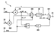
図2は、本発明による完全デジタルパルスパターン発生器の主要な要素を示す。パルス周期カウンタ2は、パルス周期TPを生成するようになっている。パルス周期カウンタ2は、インクリメントワードINC1を供給する入力端子28を備える。インクリメントワードINC1は、期間TPに対応する。パルス周期カウンタデバイス2は、インクリメントワードINC1を処理することによって、期間TPに対応する開始信号を生成するようになっている。周期カウンタデバイス2についてのより詳細な図は、図5に見ることができる。
FIG. 2 shows the main elements of a fully digital pulse pattern generator according to the invention.
周期カウンタデバイス2は、入力端子243及び出力端子245を有するレジスタ24を備える。出力は、加算要素27に結合するフィードバックパス246に接続される。要素27は、レジスタ24の結果とインクリメントワードINC1を加算し、新しい入力値として、結果をレジスタ24の入力243に供給する。レジスタ24は、リセット信号及び開始信号用の付加的な入力端子241及び242を有する。レジスタの出力端子245は、開始信号の生成のために、オーバフロー検出及びオーバフローカウンタ25に接続される。
The
動作時、周期カウンタ2は、出力端子21において開始信号を出力する。2つの開始信号間の期間は、レジスタ24の長さ、基準クロックCLK、及びインクリメントワードINC1によって与えられる期間TPに相当する。しかしながら、インクリメントワード及びパルス周期TPは、基準クロックサイクルの非整数倍であるであろう。
In operation, the
非制限的な例として、周期カウンタデバイス2のレジスタ長は32ビットであり、高安定基準クロックCLKは、1/229秒の基準クロックの周期に相当する229Hzの周波数を含む。所望の期間TPが125ミリ秒(ms)であると仮定する。これは、64のインクリメントワードINC1をもたらすことになる。換言すれば、基準クロックサイクル毎に、レジスタの値が、64だけインクリメントされる。レジスタの値が、レジスタ長によって規定された232である最大値に達するとすぐに、図5によるオーバフロー検出回路25によって検出されるオーバフローが起こることになる。開始信号は、その後、出力端子21において送出され、レジスタは、再び満たされる。125msの期間すなわち8Hzは、229Hzの整数倍であることによって、オフセットは生成されない。
As a non-limiting example, the register length of the
しかしながら、選択されるパルス周期TPが基準クロックサイクルの整数倍でない場合、レジスタオーバフローが起こることになる。新しいレジスタの値は、ゼロではないことになる。 However, if the pulse period T P chosen is not an integer multiple of the reference clock cycle, so that the register overflow occurs. The new register value will not be zero.
こうした振る舞いは、所定期間にわたる周期カウンタ2のレジスタ24の値の図を示す図9の(a)(上側の図)に見ることができる。レジスタの値は、基準クロックサイクル毎にインクリメントワ−ドINC1だけインクリメントされる。たとえば、7基準クロックサイクル後、レジスタは値Z2を保持する。8基準クロックサイクル後、レジスタは、レジスタ長RLよりわずかに小さい値Z3を保持する。レジスタの値の次のインクリメントは、レジスタ24のオーバフロー値Z4をもたらすことになる。
Such a behavior can be seen in FIG. 9 (a) (upper diagram) showing a diagram of the value of the
こうしたオーバフローが考慮されない場合、次のパルスは、所望の時点TPではなく、時点TP1で開始することになる。こうした振る舞いは、位相オフセットを生成し、図9の(b)(下側の図)に見ることができる期間エラーをもたらす。図9の(b)は、立上がりエッジTR、ハイ状態時間TH、及び時間TFを有する立下がりエッジを有する期間TPの例示的なパルスを示す。さらなるロー状態時間TL後、パルス信号は、時点TPで再び繰り返されるものとする。しかしながら、周期カウンタのレジスタのエラーによって、パルスの開始点は、レジスタオーバフローによって与えられる或るオフセットだけ遅延する。 If such overflow is not taken into account, the next pulse will start at time T P1 rather than the desired time T P. Such behavior creates a phase offset, resulting in a period error that can be seen in FIG. 9b (bottom view). FIG. 9 (b) shows an exemplary pulse of time period T P having a falling edge having a rising edge T R , a high state time T H , and a time T F. After a further low state time T L , the pulse signal shall be repeated again at time T P. However, due to an error in the register of the period counter, the starting point of the pulse is delayed by some offset given by the register overflow.
したがって、図5によるオーバフロー検出デバイス25は、オーバフロー検出回路だけでなく、レジスタ24のオーバフロー値を決定することが可能なオーバフローカウンタもまた備える。オフセット値は、出力端子254で出力され、スケーリングユニット26に設定される。スケーリングユニット26の出力は、周期カウンタの出力22に接続される。周期カウンタデバイス2の出力端子22は、期間に対応するインクリメントワードINC1と全体的な基準クロックCLKとの間の位相オフセットを表す第1オフセットワードΦ1を提供する。
Accordingly, the
換言すれば、周期カウンタデバイスは、基準クロックサイクルCLKごとにインクリメントワードINCをレジスタの値に加える再生式レジスタを備える。オーバフロー後、レジスタは、0〜インクリメントワードINC1までの新しい値を保持する。新しい値は、パルスの幅及びエッジを生成する時に考慮されなければならない、基準クロックCLKに対する位相オフセット、すなわち遅延を表す。新しい値は、出力端子21に開始信号を、出力22にオフセットワードΦ1を生成するオーバフロー検出及びオーバフローカウンタ回路によって取得される。オーバフロー検出回路及びオーバフローカウンタデバイス25は、パルス信号の立上がりエッジを開始するためのさらなる遅延を可能にする。
In other words, the period counter device comprises a regenerative register that adds an increment word INC to the register value every reference clock cycle CLK. After overflow, the register holds a new value from 0 to the increment word INC1. The new value represents the phase offset or delay relative to the reference clock CLK that must be considered when generating the pulse width and edge. The new value is obtained by an overflow detection and overflow counter circuit that generates a start signal at
開始信号及び第1オフセットワードΦ1は、その後、本発明によるデジタル式立上がりエッジ発生器3に供給される。
The start signal and the first offset word Φ1 are then supplied to the digital rising
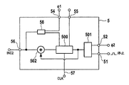
立上がり時間とハイ状態の時間によって決定されるパルス幅を設定するために、デジタル式パルスパターン発生器1aは、周期カウンタ2の出力21及び22に結合する、さらなる幅カウンタ5を備える。幅カウンタ5は、パルス幅TWに相当するインクリメントワードINC2用のさらなる入力端子56を備える。幅カウンタ5の例示的な一実施形態は、図6に見られる。幅カウンタ5は、周期カウンタと同様に、オーバフロー検出及びオーバフローカウンタ回路501に接続される出力を有するレジスタ500を備える。レジスタ500の出力は、加算要素502にフィードバックされ、加算要素502は、レジスタ500の出力とインクリメントワードINC2を加算する。結果は、レジスタの値に再び置き換わる。
In order to set the pulse width determined by the rise time and the high state time, the digital
幅カウンタデバイス5は、周期カウンタ2の出力端子21に接続される入力端子54から開始信号を受け取ることになることを除いて、周期カウンタデバイス2と同じ機能を有する。さらに、幅カウンタ5は、開始信号の検出によって、第1オフセットワードΦ1及びインクリメントワードINC2を考慮して、レジスタ500に記憶されるオフセット位置を計算する計算ユニット58を備える。レジスタ500に記憶されるオフセット値は、パルスの立上がりエッジの開始点と基準クロックサイクルのと間の遅延に相当する。レジスタの長さ及びインクリメントワードINC2は、総パルス幅TWに相当する。検出ユニット501によって、レジスタ500のオーバフローが検出されるとすぐ、停止信号が出力端子51に生成される。レジスタ500はまた、オーバフロー値を保持し、オーバフロー値は、オーバフロー検出及びオーバフローカウンタユニット501によって取得され、第2オフセットワードΦ2として出力端子52に出力される。
The
幅カウンタデバイス5の出力は、その後、図4で先に説明したように、立下がりエッジ発生器6に供給される。
The output of the
さらに、図2によるデジタルパルスパターン発生器1aは、2つの入力端子41及び42を有するスイッチングユニット4を備える。入力端子41は、立上がりエッジ発生器3の出力端子31に接続される。スイッチングユニット4の第2入力端子42は、立下がりエッジ発生器6の出力端子61に接続される。スイッチングユニット4は、デジタル・アナログ変換器135に結合される出力端子43を備える。スイッチングユニット4は、その対応する入力の1つを出力端子43に切り換えるようになっている。スイッチングユニット4は、制御ユニット7のデータ出力73に接続される設定端子45を備える。制御ユニット7は、2つの入力端子71及び72を備える。
Furthermore, the digital
入力端子71は、開始信号のために、周期カウンタ2の出力端子21に接続される。第2入力端子72は、幅カウンタデバイス5の出力端子51に接続される。対応する入力端子71及び72上の開始信号及び停止信号の状態に応じて、制御ユニット7は、信号を出力し、それによって、ユニット4を切り換える。より詳細には、入力端子71に開始信号が存在する場合、制御ユニット7は、スイッチングユニット4を第1の状態に切り換え、入力端子41を出力端子43に結合する。停止信号が存在するとすぐに、立下がりエッジの始めに対応して、制御ユニット7は、スイッチングユニット4を第2の状態に設定し、それによって、入力42を出力43に結合する。
The
制御ユニット7は、フリップフロップとして構成されることができ、データ入力は第1入力端子71に対応し、リセット入力は第2入力端子72に対応する。開始信号が存在する時、フリップフロップが、幅カウンタデバイス5が提供する停止信号によってリセットされない限り、フリップフロップのデータ出力上にハイ状態が出力される。
The
図1は、本発明によるパルスパターン発生器1のさらなる一実施形態を示す。この実施形態では、周期カウンタデバイス2は、第1スイッチングユニット16の第1入力端子161に接続される。スイッチングユニット16の第2入力端子162は、外部開始トリガを供給するためのトリガ計算ユニット17に結合される。同様に、外部クロック又は外部立上がりエッジは、スイッチングユニット16の入力端子162によって、デジタルパルスパターン発生器に供給することができる。
FIG. 1 shows a further embodiment of a
スイッチングユニット16の出力端子は、立上がりエッジ発生器3及び幅カウンタデバイス5の入力端子に接続される。立下がりエッジ発生器6は、その入力が、第2スイッチングユニット15に接続される。第2スイッチングユニット15はまた、2つの入力端子151及び152を備える。入力端子151は、幅カウンタデバイス5の出力に接続される。第2入力端子152は、トリガ計算ユニット17に接続される。第2入力端子152は、外部クロック信号を立下がりエッジ発生器6に供給するようになっている。
The output terminal of the switching
2つの付加的なスイッチ16及び15を使用することによって、外部トリガ、外部クロック、或いは外部立上がりエッジ又は立下がりエッジを使用して、より柔軟性のあるデジタルパターン発生が可能になる。
Using two
トリガ計算ユニット17の入力は、デジタルパルスパターン発生器1の入力端子181におけるアナログトリガ信号を変換するために、高速アナログ・デジタル変換器18に接続される。高速アナログ・デジタル変換器18によって提供されるデジタルトリガ信号は、トリガ計算ユニット17によって処理される。入力181におけるトリガ開始信号とデジタルパルスパターン発生器1の高速基準クロックとの間の任意の遅延は、後でパルス信号を生成するために、考慮され且つ補償される。換言すれば、トリガ計算ユニットは、トリガパルスと基準クロックの間の任意の位相遅延を補償し、トリガパルスについての処理時間をさらに補償する。
The input of the
スイッチングユニット4の出力端子は、メモリルックアップテーブル11に接続される。デジタルパルスパターン発生器によって生成される出力値Wは、メモリルックアップテーブル用の引数として使用される。メモリルックアップテーブル11は、位相制御ワードWに対して対応する値を記憶するようになっている。対応する値は、パルスパターンを変形させるのに使用することができる。メモリルックアップテーブル11の出力は、望ましくない信号部分を抑圧するフィルタ12に接続され、次に、出力計算又は掛け算ユニット13用の入力として使用される。ユニット13の出力は、アナログパルス信号を生成するために、デジタル・アナログ変換器に接続される。アナログパルス信号は、付加的な増幅器14によって増幅され、次に、パルスパターン発生器1の出力端子19に供給される。
The output terminal of the switching unit 4 is connected to the memory lookup table 11. The output value W generated by the digital pulse pattern generator is used as an argument for the memory lookup table. The memory lookup table 11 stores a corresponding value for the phase control word W. The corresponding value can be used to deform the pulse pattern. The output of the memory look-up table 11 is connected to a
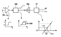
図12は、トリガ計算ユニット17及びアナログ・デジタル変換ユニット184の一実施形態を示す。一般に、トリガ信号は、アクションをトリガするか、又は、起動するのに使用される。パルスパターン発生器の場合、トリガは、パターン発生を起動するのに、より詳細には、第1パルスを開始させるのに使用することができる。トリガの受け取りとトリガされるプロセスの起動の間の遅延は、できる限り小さく保たれることが望ましい。さらに、遅延が一定に保たれることが重要である。このことは、完全デジタルパターン発生器の場合、トリガ信号が、2つの連続する基準クロックサイクルの間にある可能性があるという問題に直接結びつく。先行の要素と共にトリガ計算ユニット17は、こうした場合に対処する。
FIG. 12 shows an embodiment of the
図12のトリガ入力端子181において受け取られるトリガ信号は、比較器183内で所与の閾値と比較される。比較器は、図からわかるように、デジタルエッジを生成する。比較器183の出力は、傾斜(スロープ)発生器182に接続され、傾斜発生器182は、比較器183からのエッジを明確な傾斜に変換するようになっている。図からわかるように、上限と下限近くでは、傾斜は、著しく非線形な振る舞いを示し、一方、上限と下限の間では、線形な上昇勾配を含む。傾斜は、高速アナログ・デジタル変換器184に伝えられる。アナログ・デジタル変換器184のサンプル周波数は、基準クロックCLKと同じであるが、より高い可能性もある。アナログ・デジタル変換器184の入力レンジは、傾斜発生器によって生成される傾斜の線形領域に設定される必要がある。さらに、傾斜は、少なくとも2つのサンプリングサイクルが伝達されるよりも速くあってはならない。最低2つのサンプルを、アナログ・デジタル変換器184の入力レンジ内で取得しなければならない。変換器184の出力は、オフセットを計算する計算ユニット17に接続される。これは、サンプリングされた直線と所与の一定のデジタル値との交点を計算することによって実施される。たとえば、デジタル一定値がd0であり、変換器184の2つのサンプルがx1/y1及びx2/y2であるとすると、オフセットΦ3は、
Φ3=(x1*(y2−d0)−x2*(y1−d0))/(y2−y1)
によって計算することができる。
The trigger signal received at the
[Phi] 3 = (x1 * (y2-d0) -x2 * (y1-d0)) / (y2-y1)
Can be calculated by:
2つの連続するサンプルx1、x2の場合、オフセットΦ3は、−y1/(y2−y1)であることになる。計算されたオフセットは、周期カウンタデバイスで使用することができる。トリガ入力を使用すると、エッジ発生器及び幅カウンタを直接制御することができる。これは、外部トリガ発生器によってパルスパターンを生成する時に、より高い柔軟性をもたらす。さらに、トリガ入力と発生器の基準クロックの間の明確な遅延のために、この考えは、パルスパターン発生についてだけでなく、全ての信号生成について使用可能である。 In the case of two consecutive samples x1 and x2, the offset Φ3 is −y1 / (y2−y1). The calculated offset can be used in the period counter device. With the trigger input, the edge generator and width counter can be controlled directly. This provides greater flexibility when generating pulse patterns with an external trigger generator. Furthermore, because of the explicit delay between the trigger input and the generator reference clock, this idea can be used for all signal generation, not just for pulse pattern generation.
パルスパターン信号の生成は、図1及び図2に示すパルスパターン発生器のようなハードウェア部品に限定されない。全ての必要なパラメータが既知であり、且つ安定性の高い基準クロックから導出される場合、パルス周期TP及びパルス幅TWを含むパルス信号の生成が可能である。図13は、本発明に従ってパルス信号を生成する方法の図を示す。 The generation of the pulse pattern signal is not limited to hardware components such as the pulse pattern generator shown in FIGS. It is all necessary parameters are known, if derived from and high reference clock stability, it is possible to generate a pulse signal including the pulse period T P and a pulse width T W. FIG. 13 shows a diagram of a method for generating a pulse signal according to the present invention.
第1ステップS1は、安定した基準クロックを提供することを含む。安定した基準クロックは、たとえば、DSPの発振器によって提供されるクロック信号、プロセッサクロック信号、又はコンピュータによって生成される内部信号であることができる。データ処理システム用の内部ハードウェアによって導出されるソフトウェアクロックさえも使用することができる。所望の信号のパルス周期TP及びパルス幅TWは、既知でなければならない。これらは、たとえば、パルス周期TPを表す信号を受け取ることによって提供される。 The first step S1 includes providing a stable reference clock. The stable reference clock can be, for example, a clock signal provided by a DSP oscillator, a processor clock signal, or an internal signal generated by a computer. Even a software clock derived by internal hardware for a data processing system can be used. The pulse period T P and the pulse width T W of the desired signal must be known. These include, for example, is provided by receiving a signal representing the pulse period T P.
図1及び図2による例では、これらの信号は、インクリメントワードINC1及びINC2に相当する。これらのワード並びに周期カウンタ2及び幅カウンタデバイス5のレジスタの長さから、パルス周期TP及びパルス幅TWを計算することができる。一方、パルス周期TP又はパルス幅TWが与えられ、レジスタのそれぞれの長さ又はカウンタの最大値が既知である場合、インクリメントワードINC1及びINC2を計算することができる。パルス周期及びパルス幅を与えた後、ステップS2にて、インクリメントワードINC1及びINC2が計算される。ステップS3にて、インクリメントワードINC1を使用して、パルス周期TPに対応して、周期カウンタデバイスは、カウンタをインクリメントし、カウンタがオーバフローを生成したかどうかを検出する。オーバフローが検出されない場合、カウンタは、インクリメントワードINC1によって再びインクリメントされることになる。ステップS3が繰り返され、オーバフローが検出された場合、ステップS4にて、オフセットワードΦ1が、オーバフロー値によって計算され、開始信号が生成される。
In the example according to FIGS. 1 and 2, these signals correspond to the increment words INC1 and INC2. From these words and the lengths of the registers of the
ステップS5にて、開始信号は、立上がりエッジカウンタを始動することになり、立上がりエッジカウンタは、第1オフセットワードΦ1から導出される開始位置に設定される。基準クロックサイクル毎に、立上がりエッジカウンタの位置が出力され、立上がりエッジカウンタは、ステップS2で与えられたインクリメントワードINCだけインクリメントされる。これは、ステップS5及びS6で行われる。もちろん、立上がりエッジの生成中に、周期カウンタが、インクリメントワードINC1によって再びインクリメントされることが述べられなければならない。 In step S5, the start signal will start the rising edge counter, which is set to a starting position derived from the first offset word Φ1. At each reference clock cycle, the position of the rising edge counter is output, and the rising edge counter is incremented by the increment word INC given in step S2. This is done in steps S5 and S6. Of course, it must be stated that during the generation of the rising edge, the period counter is incremented again by the increment word INC1.
開始信号はまた、パルス幅TWの生成に使用される。ステップS4で生成されるオフセットワードは、付加的なカウンタ用の開始位置として、ステップS7にて使用され、付加的なカウンタは、第2インクリメントワードINC2だけインクリメントされる。第2カウンタがオーバフローを生成するとすぐに、ステップS9にて、オーバフローが検出されることになり、停止信号が生成される。さらに、ステップS7にて、第2カウンタのオーバフロー値から導出される第2オフセットワードΦ2が生成される。立下がりエッジは、ステップS10にて、停止信号及び第2オフセットワードを使用して生成される。立下がりエッジは、その後、ステップS11にて出力される。 Start signal is also used to generate the pulse width T W. The offset word generated in step S4 is used in step S7 as a starting position for the additional counter, and the additional counter is incremented by the second increment word INC2. As soon as the second counter generates an overflow, an overflow is detected in step S9 and a stop signal is generated. Further, in step S7, a second offset word Φ2 derived from the overflow value of the second counter is generated. A falling edge is generated in step S10 using the stop signal and the second offset word. The falling edge is then output in step S11.
カウンタをインクリメントする方法ステップは並列に実施される。そのため、立上がりエッジが生成され、出力されている間に、パルス周期及びパルス幅カウンタがインクリメントされる。本方法で生成されるデジタルパルスパターンは、アナログパルス信号に変換されることが明らかである。しかしながら、全てのパルスパラメータは、完全にデジタルで生成される。 The method steps for incrementing the counter are performed in parallel. Therefore, the pulse period and pulse width counter are incremented while the rising edge is generated and output. It is clear that the digital pulse pattern generated by this method is converted into an analog pulse signal. However, all pulse parameters are generated completely digitally.
36:加算要素
38:レジスタ
300、301:スイッチ
302:掛け算器
303:遅延要素
36: Addition element 38:
Claims (20)
インクリメント信号及びオフセット信号を受け取る少なくとも1つの入力端子と、
前記オフセット信号と前記インクリメント信号とに基づいてカウンタ開始値を決定するようになっている開始値回路と、
前記カウンタ開始値に設定されるようになっており、前記基準クロック信号の各サイクルにおいて、規定の値が達成されるまで、カウンタの位置を前記インクリメント信号に従って新しい値に変更する前記カウンタと、
前記カウンタ値を出力する出力端子と、
を備えている信号発生器。 A signal generator that generates a signal edge using a sequence of digital values spaced according to a reference clock signal,
At least one input terminal for receiving an increment signal and an offset signal;
A start value circuit adapted to determine a counter start value based on the offset signal and the increment signal;
The counter is set to a starting value, and in each cycle of the reference clock signal, the counter changes the position of the counter to a new value according to the increment signal until a specified value is achieved;
An output terminal for outputting the counter value;
A signal generator.
前記開始信号及び第1オフセット信号を生成するようになっている周期カウンタであって、前記開始信号は基準クロックと所与のパルス周期とから導出され、前記第1オフセット信号は前記基準クロックと前記所与のパルス幅とから導出され、前記周期カウンタの出力は、第1デジタルエッジ発生器のそれぞれの入力に接続される、前記周期カウンタと、
前記周期カウンタに結合され、所与のパルス幅と、前記基準クロックと、前記開始信号に対する前記第1オフセット信号とから導出される第2オフセット信号および停止信号を生成するようになっている幅カウンタであって、該幅カウンタの出力は、第2デジタルエッジ発生器のそれぞれの入力に接続される、幅カウンタと、
をさらに備えているデジタルパルス信号発生器。 A digital pulse signal generator for generating a pulse signal by the first signal generator and the second signal generator according to any one of claims 1 to 9,
A period counter adapted to generate the start signal and a first offset signal, wherein the start signal is derived from a reference clock and a given pulse period, and the first offset signal is derived from the reference clock and the The period counter, derived from a given pulse width, the output of the period counter connected to a respective input of a first digital edge generator;
A width counter coupled to the period counter and adapted to generate a second offset signal and a stop signal derived from a given pulse width, the reference clock, and the first offset signal relative to the start signal The output of the width counter is connected to a respective input of a second digital edge generator;
A digital pulse signal generator further comprising:
インクリメント信号及びオフセット信号を受け取るステップと、
前記オフセット信号及び前記インクリメント信号に基づいてカウンタ開始値を決定するステップと、
カウンタを前記カウンタ開始値に設定し、前記基準クロック信号の各サイクルにおいて、規定の値が達成されるまで、前記カウンタの位置を前記インクリメント信号に従って新しい値に変更するステップと、
前記カウンタ値を出力するステップと、
を含む、方法。 A method of generating a sequence of spaced digital values according to a reference clock signal,
Receiving an increment signal and an offset signal;
Determining a counter start value based on the offset signal and the increment signal;
Setting a counter to the counter start value and changing the position of the counter to a new value according to the increment signal until a specified value is achieved in each cycle of the reference clock signal;
Outputting the counter value;
Including a method.
20. A software program or product for controlling the steps of claim 19, preferably stored on a data carrier and executed on a data processing system such as a computer.
Applications Claiming Priority (1)
| Application Number | Priority Date | Filing Date | Title |
|---|---|---|---|
| EP05104301A EP1724923B1 (en) | 2005-05-20 | 2005-05-20 | Signal generation |
Publications (1)
| Publication Number | Publication Date |
|---|---|
| JP2006333473A true JP2006333473A (en) | 2006-12-07 |
Family
ID=35219607
Family Applications (1)
| Application Number | Title | Priority Date | Filing Date |
|---|---|---|---|
| JP2006141916A Pending JP2006333473A (en) | 2005-05-20 | 2006-05-22 | Signal generating apparatus and method |
Country Status (4)
| Country | Link |
|---|---|
| US (1) | US20060282715A1 (en) |
| EP (1) | EP1724923B1 (en) |
| JP (1) | JP2006333473A (en) |
| DE (1) | DE602005004652T2 (en) |
Families Citing this family (2)
| Publication number | Priority date | Publication date | Assignee | Title |
|---|---|---|---|---|
| DE102010049856B4 (en) * | 2010-10-27 | 2016-08-18 | Fujitsu Technology Solutions Intellectual Property Gmbh | Control circuit and method for speed control, data processing device and program code |
| CN112671491B (en) * | 2020-12-10 | 2022-07-29 | 成都引众数字设备有限公司 | Direct-current B code transmission delay compensation method and device |
Citations (3)
| Publication number | Priority date | Publication date | Assignee | Title |
|---|---|---|---|---|
| JPS6436116A (en) * | 1987-07-31 | 1989-02-07 | Nec Corp | Timing pulse generating circuit |
| JPH03186776A (en) * | 1989-12-15 | 1991-08-14 | Yokogawa Electric Corp | Waveform formatting circuit |
| JP2000002757A (en) * | 1998-04-10 | 2000-01-07 | Sony Tektronix Corp | Data.pattern generator |
Family Cites Families (6)
| Publication number | Priority date | Publication date | Assignee | Title |
|---|---|---|---|---|
| JPH0614610B2 (en) * | 1984-12-17 | 1994-02-23 | 沖電気工業株式会社 | Pulse width control circuit |
| JPH077904B2 (en) * | 1987-09-14 | 1995-01-30 | 三菱電機株式会社 | Pulse generator |
| US5068755A (en) * | 1990-06-01 | 1991-11-26 | Micropolis Corporation | Sector pulse generator for hard disk drive assembly |
| US5933453A (en) * | 1997-04-29 | 1999-08-03 | Hewlett-Packard Company | Delta-sigma pulse width modulator control circuit |
| US7548941B2 (en) * | 2004-06-18 | 2009-06-16 | Analog Devices, Inc. | Digital filter using memory to emulate variable shift register |
| US7305569B2 (en) * | 2004-06-29 | 2007-12-04 | Intel Corporation | Apparatus, system and method for adjusting a set of actual power states according to a function depending on a set of desired power states |
-
2005
- 2005-05-20 EP EP05104301A patent/EP1724923B1/en not_active Ceased
- 2005-05-20 DE DE602005004652T patent/DE602005004652T2/en not_active Expired - Fee Related
-
2006
- 2006-03-31 US US11/396,169 patent/US20060282715A1/en not_active Abandoned
- 2006-05-22 JP JP2006141916A patent/JP2006333473A/en active Pending
Patent Citations (3)
| Publication number | Priority date | Publication date | Assignee | Title |
|---|---|---|---|---|
| JPS6436116A (en) * | 1987-07-31 | 1989-02-07 | Nec Corp | Timing pulse generating circuit |
| JPH03186776A (en) * | 1989-12-15 | 1991-08-14 | Yokogawa Electric Corp | Waveform formatting circuit |
| JP2000002757A (en) * | 1998-04-10 | 2000-01-07 | Sony Tektronix Corp | Data.pattern generator |
Also Published As
| Publication number | Publication date |
|---|---|
| EP1724923A1 (en) | 2006-11-22 |
| EP1724923B1 (en) | 2008-02-06 |
| DE602005004652D1 (en) | 2008-03-20 |
| DE602005004652T2 (en) | 2008-06-05 |
| US20060282715A1 (en) | 2006-12-14 |
Similar Documents
| Publication | Publication Date | Title |
|---|---|---|
| CN112564698B (en) | Calibrating an interpolating divider using a virtual phase-locked loop | |
| US20070291173A1 (en) | Phase lock loop and digital control oscillator thereof | |
| CN109142820B (en) | Pulse wave generating device | |
| JP4620931B2 (en) | Noise shaping and digital frequency synthesis | |
| JP2009005288A (en) | Clock generation circuit | |
| JPH11234129A (en) | Frequency synthesizer and method therefor | |
| US7180339B2 (en) | Synthesizer and method for generating an output signal that has a desired period | |
| WO2010047005A1 (en) | Digital pll circuit and communication apparatus | |
| JPH066212A (en) | Phase comparator circuit and phase locked oscillator circuit using the same | |
| JP4648380B2 (en) | Fractional frequency synthesizer | |
| JP6695378B2 (en) | Generation of pulse width modulated signal frequency | |
| CN108572266B (en) | Waveform generating device | |
| JP2006333473A (en) | Signal generating apparatus and method | |
| JP2003088131A (en) | PWM circuit and inverter device using the PWM circuit | |
| US7072920B2 (en) | Method and apparatus for digital frequency conversion | |
| WO2007031940A2 (en) | Generating a pulse signal with a modulated duty cycle | |
| US7339412B2 (en) | Digital clock generator | |
| JP3779863B2 (en) | Phase shift oscillation circuit | |
| KR100316533B1 (en) | Floating point frequency composition apparatus using multi-output phase locked loop | |
| JPH07297713A (en) | Frequency synthesizer | |
| JP4498963B2 (en) | Digital system | |
| JP2011055118A (en) | Spread spectrum clock generation device | |
| JP3915024B2 (en) | Clock synchronization circuit | |
| JP4593261B2 (en) | Frequency synthesizer and reference signal phase setting method thereof | |
| JP4563165B2 (en) | Frequency synthesizer and reference signal phase setting method thereof |
Legal Events
| Date | Code | Title | Description |
|---|---|---|---|
| A621 | Written request for application examination |
Free format text: JAPANESE INTERMEDIATE CODE: A621 Effective date: 20090511 |
|
| A977 | Report on retrieval |
Free format text: JAPANESE INTERMEDIATE CODE: A971007 Effective date: 20110831 |
|
| A131 | Notification of reasons for refusal |
Free format text: JAPANESE INTERMEDIATE CODE: A131 Effective date: 20111014 |
|
| A02 | Decision of refusal |
Free format text: JAPANESE INTERMEDIATE CODE: A02 Effective date: 20120306 |