JP2007192578A - 半導体検査装置 - Google Patents
半導体検査装置 Download PDFInfo
- Publication number
- JP2007192578A JP2007192578A JP2006008875A JP2006008875A JP2007192578A JP 2007192578 A JP2007192578 A JP 2007192578A JP 2006008875 A JP2006008875 A JP 2006008875A JP 2006008875 A JP2006008875 A JP 2006008875A JP 2007192578 A JP2007192578 A JP 2007192578A
- Authority
- JP
- Japan
- Prior art keywords
- handler
- handlers
- test head
- connection position
- semiconductor inspection
- Prior art date
- Legal status (The legal status is an assumption and is not a legal conclusion. Google has not performed a legal analysis and makes no representation as to the accuracy of the status listed.)
- Granted
Links
- 239000004065 semiconductor Substances 0.000 title claims abstract description 43
- 238000007689 inspection Methods 0.000 title claims abstract description 25
- 238000012360 testing method Methods 0.000 claims abstract description 45
- 238000004891 communication Methods 0.000 claims description 2
- 239000013256 coordination polymer Substances 0.000 abstract description 18
- 238000004519 manufacturing process Methods 0.000 abstract description 5
- 238000000034 method Methods 0.000 description 4
- 230000008878 coupling Effects 0.000 description 3
- 238000010168 coupling process Methods 0.000 description 3
- 238000005859 coupling reaction Methods 0.000 description 3
- 238000010586 diagram Methods 0.000 description 3
- 238000007796 conventional method Methods 0.000 description 2
- 238000004904 shortening Methods 0.000 description 2
- 238000012546 transfer Methods 0.000 description 2
- 238000003795 desorption Methods 0.000 description 1
- 238000009434 installation Methods 0.000 description 1
- 239000000463 material Substances 0.000 description 1
Images



Landscapes
- Testing Of Individual Semiconductor Devices (AREA)
Abstract
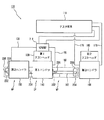
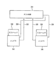
【解決手段】テスタ本体110とケーブル120により接続されるとともにテストヘッド130と連結可能な複数のハンドラ140,150と、各ハンドラ140,150をテストヘッド130と連結される連結位置CPと連結位置CPから離隔した待機位置WPとの間で移動自在とするハンドラ移動部160とを備え、連結位置CPにて複数のハンドラ140,150のうちの一つがテストヘッド130と選択的に連結されるよう構成される。
【選択図】図1
Description
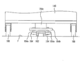
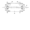
図5に示すように、半導体検査装置100は、各ハンドラ140,150を連結位置CP及び待機位置WPで位置決めする位置決め部200を備えている。位置決め部200は、各ハンドラ140,150の側部に設けられたピン部材202と、連結位置CP及び待機位置WPの床面F側に設けられピン部材202を受容する穴部204と、を有している。
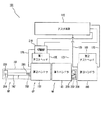
第1テストヘッド130における各ハンドラ140,150の入れ替えに際して、作業者は、ピン部材202を穴部204から抜脱して各ハンドラ140,150をレール162に沿って移動可能な状態とする。この後、各ハンドラ140,150を連結位置CP及び待機位置WPに移動させて、ピン部材202を穴部204に挿入して位置決めを行う。そして、切替部210にてケーブル120の切替操作を行い、新たに連結されたハンドラ140,150のケーブル120を使用可能な状態とする。
110 テスタ本体
120 ケーブル
130 第1テストヘッド
140 第1ハンドラ
150 第2ハンドラ
160 ハンドラ移動部
162 レール
164 補助輪
164a 回転軸
164b 支持材
164c 床下部材
166 キャスタ
170 ケーブル
180 第2テストヘッド
190 第3ハンドラ
200 位置決め部
202 ピン部材
204 穴部
206 操作レバー
208 端部ブロック
210 切替部
310 テスタ本体
320 ケーブル
330 テストヘッド
340 ハンドラ
400 電動リフタ
CP 連結位置
F 床面
WP 待機位置
Claims (4)
- テスタ本体とケーブルにより接続されるとともに、テストヘッドと連結可能な複数のハンドラと、
前記各ハンドラを、前記テストヘッドと連結される連結位置と、該連結位置から離隔した待機位置と、の間で移動自在とするハンドラ移動部と、を備え、
前記連結位置にて前記複数のハンドラのうちの一つが前記テストヘッドと選択的に連結されることを特徴とする半導体検査装置。 - 前記各ケーブルにおいて前記テスタ本体と前記各ハンドラとの間に介在し、前記テスタ本体との通信に使用する前記ケーブルを切替自在にする切替部をさらに備えることを特徴とする請求項1に記載の半導体検査装置。
- 前記各ハンドラを前記連結位置及び前記待機位置で位置決めする位置決め部をさらに備えることを特徴とする請求項1または2に記載の半導体検査装置。
- 前記ハンドラ移動部は、前記連結位置から前記待機位置まで延び、前記各ハンドラを案内するレールを有することを特徴とする請求項1から3のいずれか一項に記載の半導体検査装置。
Priority Applications (1)
| Application Number | Priority Date | Filing Date | Title |
|---|---|---|---|
| JP2006008875A JP4695987B2 (ja) | 2006-01-17 | 2006-01-17 | 半導体検査装置 |
Applications Claiming Priority (1)
| Application Number | Priority Date | Filing Date | Title |
|---|---|---|---|
| JP2006008875A JP4695987B2 (ja) | 2006-01-17 | 2006-01-17 | 半導体検査装置 |
Publications (2)
| Publication Number | Publication Date |
|---|---|
| JP2007192578A true JP2007192578A (ja) | 2007-08-02 |
| JP4695987B2 JP4695987B2 (ja) | 2011-06-08 |
Family
ID=38448407
Family Applications (1)
| Application Number | Title | Priority Date | Filing Date |
|---|---|---|---|
| JP2006008875A Expired - Fee Related JP4695987B2 (ja) | 2006-01-17 | 2006-01-17 | 半導体検査装置 |
Country Status (1)
| Country | Link |
|---|---|
| JP (1) | JP4695987B2 (ja) |
Citations (5)
| Publication number | Priority date | Publication date | Assignee | Title |
|---|---|---|---|---|
| JPS60114978U (ja) * | 1984-01-10 | 1985-08-03 | 日本電気株式会社 | Icテスト装置 |
| JPH0357940U (ja) * | 1989-10-06 | 1991-06-05 | ||
| JPH0513535A (ja) * | 1991-07-05 | 1993-01-22 | Mitsubishi Electric Corp | テストヘツド着脱装置 |
| JPH08211123A (ja) * | 1994-11-24 | 1996-08-20 | Advantest Corp | テスト・ヘッド接続装置を装備した半導体試験装置 |
| JP2003098224A (ja) * | 2001-09-25 | 2003-04-03 | Santo Technology Kk | 半導体試験装置 |
-
2006
- 2006-01-17 JP JP2006008875A patent/JP4695987B2/ja not_active Expired - Fee Related
Patent Citations (5)
| Publication number | Priority date | Publication date | Assignee | Title |
|---|---|---|---|---|
| JPS60114978U (ja) * | 1984-01-10 | 1985-08-03 | 日本電気株式会社 | Icテスト装置 |
| JPH0357940U (ja) * | 1989-10-06 | 1991-06-05 | ||
| JPH0513535A (ja) * | 1991-07-05 | 1993-01-22 | Mitsubishi Electric Corp | テストヘツド着脱装置 |
| JPH08211123A (ja) * | 1994-11-24 | 1996-08-20 | Advantest Corp | テスト・ヘッド接続装置を装備した半導体試験装置 |
| JP2003098224A (ja) * | 2001-09-25 | 2003-04-03 | Santo Technology Kk | 半導体試験装置 |
Also Published As
| Publication number | Publication date |
|---|---|
| JP4695987B2 (ja) | 2011-06-08 |
Similar Documents
| Publication | Publication Date | Title |
|---|---|---|
| KR101168903B1 (ko) | 테스트 헤드 및 이를 구비한 반도체 웨이퍼 시험장치 | |
| KR101606569B1 (ko) | 차량용 케이블의 검사장치 | |
| EP1495339B1 (en) | Semiconductor test system with easily changed interface unit | |
| WO2007130763A1 (en) | Automated programming system employing smart interfaces | |
| JP2009505417A (ja) | テストハンドラー | |
| JP2013118770A (ja) | 電気車制御装置 | |
| JP4695987B2 (ja) | 半導体検査装置 | |
| JP2006322918A (ja) | インターフェース、及びそれを用いた半導体テスト装置 | |
| JP2010067679A (ja) | 電子部品実装装置およびパーツフィーダ交換用台車 | |
| CN103728505B (zh) | 检查装置 | |
| JPH0254877A (ja) | 自動接続装置 | |
| EP1604799A1 (en) | Extracting device for molded articles | |
| JP2001201528A (ja) | 配線基板等の導通試験装置 | |
| JP2006181680A (ja) | ワーク位置決め搬送装置,ワーク位置決め方法およびワーク位置決め搬送台車 | |
| CN109906004B (zh) | 自动布线机器人 | |
| JP2006308450A (ja) | 表示用基板を受けるワークテーブルの交換装置及び表示用基板の検査装置 | |
| KR20070028023A (ko) | 테스트 지그 유닛 | |
| KR20090063721A (ko) | 차량용 퓨즈 풀러 | |
| JP4172546B2 (ja) | 車両走行試験用接続システム | |
| JP2005523457A (ja) | 制御されたコンプライアンスを有する単一軸マニプレーター | |
| JP4960147B2 (ja) | 電子部品実装装置本体及び電子部品実装装置 | |
| KR102928673B1 (ko) | 전동 개폐 장치 | |
| JP4685336B2 (ja) | Tftアレイ検査装置 | |
| KR20070024796A (ko) | 프로브카드 세정장치 | |
| CN204631561U (zh) | 嵌入式机床控制柜 |
Legal Events
| Date | Code | Title | Description |
|---|---|---|---|
| A621 | Written request for application examination |
Effective date: 20081113 Free format text: JAPANESE INTERMEDIATE CODE: A621 |
|
| A977 | Report on retrieval |
Effective date: 20100927 Free format text: JAPANESE INTERMEDIATE CODE: A971007 |
|
| A131 | Notification of reasons for refusal |
Effective date: 20101012 Free format text: JAPANESE INTERMEDIATE CODE: A131 |
|
| A521 | Written amendment |
Free format text: JAPANESE INTERMEDIATE CODE: A523 Effective date: 20101202 |
|
| A131 | Notification of reasons for refusal |
Free format text: JAPANESE INTERMEDIATE CODE: A131 Effective date: 20101221 |
|
| A521 | Written amendment |
Free format text: JAPANESE INTERMEDIATE CODE: A523 Effective date: 20110201 |
|
| TRDD | Decision of grant or rejection written | ||
| A01 | Written decision to grant a patent or to grant a registration (utility model) |
Free format text: JAPANESE INTERMEDIATE CODE: A01 Effective date: 20110222 |
|
| A01 | Written decision to grant a patent or to grant a registration (utility model) |
Free format text: JAPANESE INTERMEDIATE CODE: A01 |
|
| A61 | First payment of annual fees (during grant procedure) |
Effective date: 20110228 Free format text: JAPANESE INTERMEDIATE CODE: A61 |
|
| FPAY | Renewal fee payment (prs date is renewal date of database) |
Free format text: PAYMENT UNTIL: 20140304 Year of fee payment: 3 |
|
| R150 | Certificate of patent (=grant) or registration of utility model |
Free format text: JAPANESE INTERMEDIATE CODE: R150 |
|
| LAPS | Cancellation because of no payment of annual fees |