JP2007252105A - モータの給電部構造 - Google Patents
モータの給電部構造 Download PDFInfo
- Publication number
- JP2007252105A JP2007252105A JP2006072758A JP2006072758A JP2007252105A JP 2007252105 A JP2007252105 A JP 2007252105A JP 2006072758 A JP2006072758 A JP 2006072758A JP 2006072758 A JP2006072758 A JP 2006072758A JP 2007252105 A JP2007252105 A JP 2007252105A
- Authority
- JP
- Japan
- Prior art keywords
- motor
- terminal
- holder
- brush holder
- yoke
- Prior art date
- Legal status (The legal status is an assumption and is not a legal conclusion. Google has not performed a legal analysis and makes no representation as to the accuracy of the status listed.)
- Granted
Links
- 230000002093 peripheral effect Effects 0.000 claims abstract description 13
- 230000013011 mating Effects 0.000 claims description 6
- 210000000078 claw Anatomy 0.000 description 8
- 229920003002 synthetic resin Polymers 0.000 description 6
- 239000000057 synthetic resin Substances 0.000 description 6
- 238000004804 winding Methods 0.000 description 4
- 238000002788 crimping Methods 0.000 description 2
- 239000000853 adhesive Substances 0.000 description 1
- 230000001070 adhesive effect Effects 0.000 description 1
- 238000000034 method Methods 0.000 description 1
Images





Landscapes
- Motor Or Generator Current Collectors (AREA)
- Motor Or Generator Frames (AREA)
Abstract
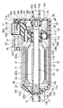
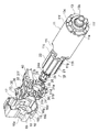
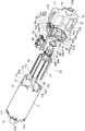
【解決手段】内周面11eに磁石12を固着した円筒状のヨーク11と、このヨーク11の開口端11cに固定され、給電用の相手カプラ40が嵌合されるカプラ受け部17を有したカバー15と、このカバー15内に収納されるブラシホルダ30と、このブラシホルダ30に設けられ、カバー15のカプラ受け部17内に配置されるターミナル36とを備えたモータ10の給電部構造において、ブラシホルダ30は、ブラシを保持するホルダ本体31と、ターミナル36をカプラ受け部17内に配置する端子保持部32とを有し、ホルダ本体31をヨーク11とカバー15との間に挾持固定した。
【選択図】図1
Description
11 ヨーク
11c 他端(開口端)
11e 内周面
12 磁石
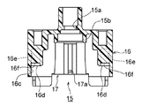
15 カバー(ケース)
17 カプラ受け部
17a 切欠孔(係合部)
18 底壁部(底部)
18a 凸部(底部)
30 ブラシホルダ
31 ホルダ本体
32 端子保持部
33 係止爪(係止部)
35 ブラシ
36 ターミナル
36b 中途部(露出部)
40 相手カプラ
Claims (3)
- 内周面に磁石を固着した筒状のヨークと、このヨークの開口端に固定され、給電用の相手カプラが嵌合されるカプラ受け部を有したケースと、このケース内に収納されるブラシホルダと、このブラシホルダに設けられ、前記ケースのカプラ受け部内に配置されるターミナルとを備えたモータの給電部構造において、
前記ブラシホルダは、ブラシを保持するホルダ本体と、前記ターミナルを前記カプラ受け部内に配置する端子保持部とを有し、前記ホルダ本体を前記ヨークと前記ケースとの間に挾持固定したことを特徴とするモータの給電部構造。 - 請求項1記載のモータの給電部構造であって、
前記ブラシホルダの端子保持部に係止部を形成し、この係止部を前記ケースのカプラ受け部の係合部に係止したことを特徴とするモータの給電部構造。 - 請求項1ないし2記載のモータの給電構部造であって、
前記端子保持部に支持されたターミナルの前記ケースのカプラ受け部の底部側を前記ブラシホルダの端子保持部の端面より外側に露出させ、このターミナルの露出部を前記ケースのカプラ受け部の底部に当接したことを特徴とするモータの給電部構造。
Priority Applications (1)
| Application Number | Priority Date | Filing Date | Title |
|---|---|---|---|
| JP2006072758A JP4875910B2 (ja) | 2006-03-16 | 2006-03-16 | モータの給電部構造 |
Applications Claiming Priority (1)
| Application Number | Priority Date | Filing Date | Title |
|---|---|---|---|
| JP2006072758A JP4875910B2 (ja) | 2006-03-16 | 2006-03-16 | モータの給電部構造 |
Publications (2)
| Publication Number | Publication Date |
|---|---|
| JP2007252105A true JP2007252105A (ja) | 2007-09-27 |
| JP4875910B2 JP4875910B2 (ja) | 2012-02-15 |
Family
ID=38595828
Family Applications (1)
| Application Number | Title | Priority Date | Filing Date |
|---|---|---|---|
| JP2006072758A Expired - Fee Related JP4875910B2 (ja) | 2006-03-16 | 2006-03-16 | モータの給電部構造 |
Country Status (1)
| Country | Link |
|---|---|
| JP (1) | JP4875910B2 (ja) |
Cited By (2)
| Publication number | Priority date | Publication date | Assignee | Title |
|---|---|---|---|---|
| JP2010178603A (ja) * | 2009-02-02 | 2010-08-12 | Tamagawa Seiki Co Ltd | レゾルバと筒状ケースとの接続固定構造 |
| DE102018209459A1 (de) * | 2018-06-13 | 2019-12-19 | Robert Bosch Gmbh | Lagerdeckel eines Gleichstrommotors |
Citations (3)
| Publication number | Priority date | Publication date | Assignee | Title |
|---|---|---|---|---|
| JP2003018790A (ja) * | 2001-07-03 | 2003-01-17 | Mitsuba Corp | 電動モータの給電部構造 |
| JP2004056920A (ja) * | 2002-07-19 | 2004-02-19 | Asmo Co Ltd | モータ |
| JP2004147377A (ja) * | 2002-10-22 | 2004-05-20 | Asmo Co Ltd | モータ |
-
2006
- 2006-03-16 JP JP2006072758A patent/JP4875910B2/ja not_active Expired - Fee Related
Patent Citations (3)
| Publication number | Priority date | Publication date | Assignee | Title |
|---|---|---|---|---|
| JP2003018790A (ja) * | 2001-07-03 | 2003-01-17 | Mitsuba Corp | 電動モータの給電部構造 |
| JP2004056920A (ja) * | 2002-07-19 | 2004-02-19 | Asmo Co Ltd | モータ |
| JP2004147377A (ja) * | 2002-10-22 | 2004-05-20 | Asmo Co Ltd | モータ |
Cited By (2)
| Publication number | Priority date | Publication date | Assignee | Title |
|---|---|---|---|---|
| JP2010178603A (ja) * | 2009-02-02 | 2010-08-12 | Tamagawa Seiki Co Ltd | レゾルバと筒状ケースとの接続固定構造 |
| DE102018209459A1 (de) * | 2018-06-13 | 2019-12-19 | Robert Bosch Gmbh | Lagerdeckel eines Gleichstrommotors |
Also Published As
| Publication number | Publication date |
|---|---|
| JP4875910B2 (ja) | 2012-02-15 |
Similar Documents
| Publication | Publication Date | Title |
|---|---|---|
| JP5462785B2 (ja) | Dcモータ | |
| JP5280932B2 (ja) | モータ | |
| CN107302275B (zh) | 旋转装置 | |
| JP5468459B2 (ja) | グラインダ | |
| JP5522342B2 (ja) | モータの電力受給のためのモータ電源端子接続部品、ブラシホルダ、およびそれらを利用したモータ | |
| JP2009112095A (ja) | モータ | |
| JP4875910B2 (ja) | モータの給電部構造 | |
| CN105830188B (zh) | 有极直流电磁铁装置和使用其的电磁接触器 | |
| JP5138963B2 (ja) | モータ | |
| WO2017110420A1 (ja) | ブラシホルダ、及びこれを備えた直流電動機 | |
| JP5307509B2 (ja) | モータ、及びサーミスタの製造方法 | |
| JP4798902B2 (ja) | 回転検知装置を備えた電動機 | |
| JP2003079109A (ja) | ブラシホルダ及び電動モータ | |
| JP2007259516A (ja) | モータ | |
| JP2007202388A (ja) | モータ | |
| JP6480150B2 (ja) | ブラシ保持機構 | |
| JP2007247663A (ja) | モータのスラスト軸受構造 | |
| JP2006211857A (ja) | 小型モータ | |
| JP6081898B2 (ja) | モータ | |
| JP4876009B2 (ja) | モータ | |
| JP2008252973A (ja) | モータ | |
| JP2008167530A (ja) | モータ | |
| JP2000209818A (ja) | モ―タにおけるブラシ保持構造及びモ―タ | |
| JP2017216824A (ja) | モータ部品およびモータ部品の製造方法 | |
| JP2014036481A (ja) | 直流電動機 |
Legal Events
| Date | Code | Title | Description |
|---|---|---|---|
| A621 | Written request for application examination |
Free format text: JAPANESE INTERMEDIATE CODE: A621 Effective date: 20090305 |
|
| A977 | Report on retrieval |
Free format text: JAPANESE INTERMEDIATE CODE: A971007 Effective date: 20110811 |
|
| A131 | Notification of reasons for refusal |
Free format text: JAPANESE INTERMEDIATE CODE: A131 Effective date: 20110825 |
|
| A521 | Request for written amendment filed |
Free format text: JAPANESE INTERMEDIATE CODE: A523 Effective date: 20111017 |
|
| TRDD | Decision of grant or rejection written | ||
| A01 | Written decision to grant a patent or to grant a registration (utility model) |
Free format text: JAPANESE INTERMEDIATE CODE: A01 Effective date: 20111114 |
|
| A01 | Written decision to grant a patent or to grant a registration (utility model) |
Free format text: JAPANESE INTERMEDIATE CODE: A01 |
|
| A61 | First payment of annual fees (during grant procedure) |
Free format text: JAPANESE INTERMEDIATE CODE: A61 Effective date: 20111128 |
|
| FPAY | Renewal fee payment (event date is renewal date of database) |
Free format text: PAYMENT UNTIL: 20141202 Year of fee payment: 3 |
|
| R150 | Certificate of patent or registration of utility model |
Free format text: JAPANESE INTERMEDIATE CODE: R150 Ref document number: 4875910 Country of ref document: JP Free format text: JAPANESE INTERMEDIATE CODE: R150 |
|
| LAPS | Cancellation because of no payment of annual fees |