JP2009299513A - Engine - Google Patents

Engine Download PDF

Info

Publication number
JP2009299513A
JP2009299513A JP2008152337A JP2008152337A JP2009299513A JP 2009299513 A JP2009299513 A JP 2009299513A JP 2008152337 A JP2008152337 A JP 2008152337A JP 2008152337 A JP2008152337 A JP 2008152337A JP 2009299513 A JP2009299513 A JP 2009299513A
Authority
JP
Japan
Prior art keywords
engine
crankshaft
shaft
output shaft
power
Prior art date
Legal status (The legal status is an assumption and is not a legal conclusion. Google has not performed a legal analysis and makes no representation as to the accuracy of the status listed.)
Pending
Application number
JP2008152337A
Other languages
Japanese (ja)
Inventor
Nobumasa Takashina
順正 高科
Yoshifumi Konishi
義史 小西
Current Assignee (The listed assignees may be inaccurate. Google has not performed a legal analysis and makes no representation or warranty as to the accuracy of the list.)
Yanmar Co Ltd
Original Assignee
Yanmar Co Ltd
Priority date (The priority date is an assumption and is not a legal conclusion. Google has not performed a legal analysis and makes no representation as to the accuracy of the date listed.)
Filing date
Publication date
Application filed by Yanmar Co Ltd filed Critical Yanmar Co Ltd
Priority to JP2008152337A priority Critical patent/JP2009299513A/en
Priority to US12/203,689 priority patent/US8230761B2/en
Publication of JP2009299513A publication Critical patent/JP2009299513A/en
Pending legal-status Critical Current

Links

Images

Landscapes

  • Lubrication Details And Ventilation Of Internal Combustion Engines (AREA)

Abstract

<P>PROBLEM TO BE SOLVED: To solve problems that the miniaturization of a vehicle is limited since a conventional engine requires spaces for disposing a counter shaft and a pair of right and left counter pulleys and for winding a belt around a crank pulley and input pulley via the counter pulleys and that working efficiency is poor since belts must be wound around respective pulleys after mounting an engine in a vehicle. <P>SOLUTION: The engine is equipped with a gear box 41 for installing therein an input shaft 34 which is disposed below a crankshaft 24 so as to be parallel with the crankshaft 24 and receives power from the crankshaft 24 via a belt mechanism 33, a first output shaft 35 which outputs power from the input shaft 34 and which is disposed perpendicular to the crankshaft 24, and a bevel gear 36 which transmits the power of the input shaft 34 to the first output shaft 35. <P>COPYRIGHT: (C)2010,JPO&INPIT

Description

本発明は、略水平方向にクランク軸を有するエンジンの技術に関し、より詳細には、クランク軸に対して垂直方向に配置された軸にクランク軸の動力を伝達する技術に関する。   The present invention relates to a technique for an engine having a crankshaft in a substantially horizontal direction, and more particularly to a technique for transmitting the power of the crankshaft to a shaft arranged in a direction perpendicular to the crankshaft.

従来、クランク軸に対して垂直方向に配置された軸にクランク軸の動力を伝達するエンジンの技術は公知となっている(例えば、特許文献1参照)。
ここで、従来例に係るエンジンを備える車両について、図29により説明する。
図29に示すようように、車両900は、アッカーマン操舵式芝刈機であって、前後水平方向にクランク軸924を有するエンジン905と、このクランク軸924に対して垂直方向に配置された入力軸906を有するモア907と、を備えている。そして、エンジン905のクランク軸924には、クランクプーリ924aが固設されているとともに、モア907の入力軸906には、入力プーリ906aが固設されている。また、エンジン905の下方には、左右水平方向にカウンター軸980が配置されており、このカウンター軸980に左右一対のカウンタープーリ980aが固設されている。そして、クランクプーリ924a、左右一対のカウンタープーリ980a、入力プーリ906aにベルト981が巻回され、エンジン905のクランク軸924の動力が、クランクプーリ924a、ベルト981、カウンタープーリ980a、ベルト981、入力プーリ906a、入力軸906に伝達されてモア907の回転刃907aが駆動される。
実開昭60−10427号公報
2. Description of the Related Art Conventionally, an engine technology for transmitting motive power of a crankshaft to a shaft arranged in a direction perpendicular to the crankshaft has been publicly known (see, for example, Patent Document 1).
Here, a vehicle including an engine according to a conventional example will be described with reference to FIG.
As shown in FIG. 29, a vehicle 900 is an Ackerman-steered lawn mower, an engine 905 having a crankshaft 924 in the front-rear horizontal direction, and an input shaft 906 arranged in a direction perpendicular to the crankshaft 924. And a mower 907. A crank pulley 924 a is fixed to the crank shaft 924 of the engine 905, and an input pulley 906 a is fixed to the input shaft 906 of the mower 907. Further, a counter shaft 980 is disposed in the horizontal direction below the engine 905, and a pair of left and right counter pulleys 980a are fixed to the counter shaft 980. The belt 981 is wound around the crank pulley 924a, the pair of left and right counter pulleys 980a, and the input pulley 906a, and the power of the crankshaft 924 of the engine 905 is supplied to the crank pulley 924a, the belt 981, the counter pulley 980a, the belt 981, and the input pulley. 906a is transmitted to the input shaft 906, and the rotary blade 907a of the mower 907 is driven.
Japanese Utility Model Publication No. 60-10427

しかし、前記従来のエンジン905は、カウンター軸980および左右一対のカウンタープーリ980aを配置するスペースや、このカウンタープーリ980aを介してクランクプーリ924aおよび入力プーリ906aにベルト981を巻回するスペースを確保する必要があるため、車両の小型化を図る上で制約になるという問題があった。また、エンジン905を車両への取付後に、ベルト981を各プーリ924a・980a・906aに巻回する必要があるため、作業効率が悪いという問題があった。   However, the conventional engine 905 secures a space for arranging the counter shaft 980 and the pair of left and right counter pulleys 980a, and a space for winding the belt 981 around the crank pulley 924a and the input pulley 906a via the counter pulley 980a. Since this is necessary, there is a problem that it becomes a limitation in reducing the size of the vehicle. Further, since the belt 981 needs to be wound around the pulleys 924a, 980a, and 906a after the engine 905 is attached to the vehicle, there is a problem that work efficiency is poor.

本発明の解決しようとする課題は以上のとおりであり、次にこの課題を解決するための手段を説明する。   The problems to be solved by the present invention are as described above. Next, means for solving the problems will be described.

すなわち、請求項1においては、略水平方向にクランク軸を有するエンジンであって、前記クランク軸の下方で、該クランク軸に対して平行に配置し、第一動力伝達手段を介して前記クランク軸からの動力を受ける入力軸と、該入力軸からの動力を出力し、前記クランク軸に対して垂直に配置する第一出力軸と、該第一出力軸に前記入力軸の動力を伝達する第二動力伝達手段と、を内装する動力伝達ケースを備えるものである。   That is, according to claim 1, the engine has a crankshaft in a substantially horizontal direction, and is arranged below the crankshaft and in parallel with the crankshaft, and the crankshaft is connected to the crankshaft via the first power transmission means. An input shaft that receives the power from the first output shaft, a first output shaft that outputs the power from the input shaft and is arranged perpendicular to the crankshaft, and a first output shaft that transmits the power of the input shaft to the first output shaft And a power transmission case that includes two power transmission means.

請求項2においては、前記第一出力軸を平面視において前記エンジンの投影範囲内に配置するものである。   According to a second aspect of the present invention, the first output shaft is disposed within the projection range of the engine in plan view.

請求項3においては、前記エンジン下部にオイルパンを備え、該オイルパンに前記動力伝達ケースを取り付けるものである。   According to a third aspect of the present invention, an oil pan is provided at the lower part of the engine, and the power transmission case is attached to the oil pan.

請求項4においては、前記エンジン下部にオイルパンを備え、前記動力伝達ケースを前記エンジンのシリンダブロックに前記オイルパンと共締めして取り付けるものである。   According to a fourth aspect of the present invention, an oil pan is provided at a lower portion of the engine, and the power transmission case is attached to a cylinder block of the engine by being fastened together with the oil pan.

請求項5においては、前記エンジン下部にオイルパンを備え、該オイルパンと前記動力伝達ケースを一体的に成型するものである。   According to a fifth aspect of the present invention, an oil pan is provided at the lower part of the engine, and the oil pan and the power transmission case are molded integrally.

請求項6においては、前記オイルパン下側に切欠き部を形成し、該切欠き部内に前記動力伝達ケースを配置するものである。   According to a sixth aspect of the present invention, a notch is formed below the oil pan, and the power transmission case is disposed in the notch.

請求項7においては、前記第一出力軸に動力出力用の第一出力部材を設けるとともに、前記第一出力軸の同軸上に該第一出力軸の動力を受ける第二出力軸を連結し、該第二出力軸に動力出力用の第二出力部材を設けるものである。   In claim 7, the first output member for power output is provided on the first output shaft, and the second output shaft that receives the power of the first output shaft is connected coaxially with the first output shaft, A second output member for power output is provided on the second output shaft.

請求項8においては、前記第一出力部材と前記第一出力軸との間および前記第二出力部材と前記第二出力軸との間の内少なくとも一方にクラッチを介設するものである。   According to an eighth aspect of the present invention, a clutch is interposed between the first output member and the first output shaft and at least one of the second output member and the second output shaft.

請求項9においては、前記動力伝達ケースには、前記クラッチが取付可能であるものである。   According to a ninth aspect of the present invention, the clutch can be attached to the power transmission case.

請求項10においては、前記第一動力伝達手段を無端帯機構とするものである。   According to a tenth aspect of the present invention, the first power transmission means is an endless belt mechanism.

請求項11においては、前記無端帯機構の無端帯に張力を付与するテンション部材を備えるものである。   According to an eleventh aspect of the present invention, a tension member that applies tension to the endless belt of the endless belt mechanism is provided.

請求項12においては、前記クランク軸および前記入力軸の内少なくとも一方の同軸上に動力取出用のPTO軸を設けるものである。   According to a twelfth aspect of the invention, a power take-out PTO shaft is provided on at least one of the crankshaft and the input shaft.

請求項13においては、前記入力軸は、冷却ファンを備えるものである。   According to a thirteenth aspect of the present invention, the input shaft includes a cooling fan.

本発明の効果として、以下に示すような効果を奏する。   As effects of the present invention, the following effects can be obtained.

請求項1においては、動力伝達ケースをコンパクトに構成して、エンジンがコンパクトになるため、車両の小型化が容易である。そして、動力伝達ケースを予めエンジンに取り付けて、モジュール化できるため、取付作業の効率性が向上する。   According to the first aspect of the present invention, since the power transmission case is made compact and the engine becomes compact, the vehicle can be easily downsized. And since a power transmission case can be previously attached to an engine and modularized, the efficiency of attachment work improves.

請求項2においては、第一出力軸をコンパクトに配置して、エンジンがコンパクトになるため、車両の小型化が容易である。   According to the second aspect of the present invention, since the first output shaft is arranged in a compact manner and the engine becomes compact, the vehicle can be easily downsized.

請求項3においては、オイルパンを利用して動力伝達ケースを簡単にエンジンに取り付けることができるため、取付作業の効率性が向上する。そして、動力伝達ケースがエンジンと同一振動系となることにより、防振対策を簡素化できるため、コストダウンが容易である。   According to the third aspect, since the power transmission case can be easily attached to the engine using the oil pan, the efficiency of the attaching operation is improved. And since a power transmission case becomes the same vibration system as an engine, since an anti-vibration measure can be simplified, cost reduction is easy.

請求項4においては、動力伝達ケースとオイルパンとを一度にシリンダブロックに取り付けることができるため、取付作業の効率性が向上する。そして、動力伝達ケースを剛性の高いシリンダブロックに取り付けるため、取り付けの確実性が向上する。また、動力伝達ケースがエンジンと同一振動系となることにより、防振対策を簡素化できるため、コストダウンが容易である。   According to the fourth aspect, since the power transmission case and the oil pan can be attached to the cylinder block at a time, the efficiency of the attaching operation is improved. And since a power transmission case is attached to a cylinder block with high rigidity, the certainty of attachment improves. In addition, since the power transmission case has the same vibration system as the engine, the anti-vibration measures can be simplified, and the cost can be easily reduced.

請求項5においては、動力伝達ケースとオイルパンとが一体となることにより、動力伝達ケースの取付作業を省略できるため、取付作業の効率性が向上するとともに、部品点数が少なくなるため、コストダウンが容易である。そして、動力伝達ケースがエンジンと同一振動系となることにより、防振対策を簡素化できるため、コストダウンが容易である。   In claim 5, since the power transmission case and the oil pan are integrated, the power transmission case mounting operation can be omitted, so that the efficiency of the mounting operation is improved and the number of parts is reduced. Is easy. And since a power transmission case becomes the same vibration system as an engine, since an anti-vibration measure can be simplified, cost reduction is easy.

請求項6においては、動力伝達ケースをコンパクトに配置して、エンジンがコンパクトになるため、車両の小型化が容易である。   According to the sixth aspect of the present invention, since the power transmission case is arranged in a compact manner and the engine becomes compact, the vehicle can be easily downsized.

請求項7においては、第一・第二出力部材を別個の駆動対象に連結して、第一・第二出力軸が複数の駆動対象に出力できるため、エンジンの利便性が向上する。   According to the seventh aspect of the present invention, the first and second output members are connected to separate driving objects, and the first and second output shafts can output to a plurality of driving objects, so that the convenience of the engine is improved.

請求項8においては、複数の駆動対象に出力可能なエンジンが、その駆動対象の内少なくとも一つへの動力の伝達・遮断が切替可能となるため、エンジンの利便性が向上する。   According to the eighth aspect of the present invention, an engine that can output to a plurality of driving targets can be switched between transmission / cut-off of power to at least one of the driving targets, and the convenience of the engine is improved.

請求項9においては、クラッチがエンジンと同一振動系となることにより、防振対策を簡素化できるため、コストダウンが容易である。   According to the ninth aspect of the present invention, since the vibration isolation system can be simplified by using the same vibration system as the engine, the cost can be easily reduced.

請求項10においては、無端帯機構という簡単な動力伝達手段にて、クランク軸の動力を入力軸に伝達できるため、コストダウンが容易であるとともに、動力伝達手段の組立作業の効率性が向上する。   In claim 10, since the power of the crankshaft can be transmitted to the input shaft by a simple power transmission means called an endless belt mechanism, the cost can be easily reduced and the efficiency of the assembly work of the power transmission means can be improved. .

請求項11においては、無端帯に張力が付与されて、無端帯の張力を調整する手間が省けるため、エンジンの利便性が向上する。   According to the eleventh aspect, since the tension is applied to the endless belt and the labor for adjusting the tension of the endless belt can be saved, the convenience of the engine is improved.

請求項12においては、作業機などの動力を取出可能となるため、エンジンの利便性が向上する。   According to the twelfth aspect, since the power of the work machine or the like can be taken out, the convenience of the engine is improved.

請求項13においては、冷却風を送風して、エンジンを効率良く冷却できる。   According to the thirteenth aspect, the engine can be efficiently cooled by blowing cooling air.

次に、発明を実施するための最良の形態を説明する。
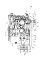
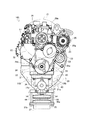
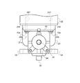
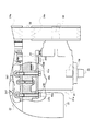
図1は本発明の第一実施例に係るエンジンを備える車両を示した側面図、図2は本発明の第一実施例に係るエンジンを示した側面一部断面図、図3は同じく正面図、図4はベルト機構を示した正面図、図5はギヤボックスを示した側面断面図、図6はギヤボックスに電磁クラッチを取り付けた状態を示した側面図、図7はギヤボックスをオイルパンに取り付けた状態を示した正面図、図8は同じく側面一部断面図、図9は本発明の第一実施例に係るベルト機構・補機駆動用ベルト機構を示した側面図、図10は本発明の第二実施例に係るエンジンを示した側面一部断面図、図11はギヤボックスをシリンダブロックにオイルパンと共締めして取り付けた状態を示した正面図、図12は同じく側面一部断面図、図13は本発明の第三実施例に係るエンジンを示した側面一部断面図、図14は一体成型したギヤボックスとオイルパンを示した側面一部断面図、図15は本発明の第四実施例に係るエンジンを示した側面一部断面図、図16はPTO軸とクランク軸前端部との連結部を示した側面図、図17は変形例に係るPTO軸とクランク軸前端部との連結部を示した側面図、図18は本発明の第五実施例に係るエンジンを示した側面図、図19は本発明の第五実施例に係るベルト機構・補機駆動用ベルト機構を示した側面図、図20は本発明の第五実施例に係るベルト機構を示した正面図、図21は本発明の第六実施例に係るエンジンを示した側面図、図22は本発明の第六実施例に係るベルト機構を示した側面図、図23は同じく正面図、図24は本発明の第六実施例に係るギヤボックス取付用のブラケットを示した正面図、図25は本発明の第七実施例に係るエンジンを示した側面図、図26は本発明の第七実施例に係るベルト機構を示した側面図、図27は同じく正面図、図28は本発明の第七実施例に係るギヤボックス取付用のブラケットを示した正面図、図29は従来例に係るエンジンを備える車両を示した側面図である。
Next, the best mode for carrying out the invention will be described.
FIG. 1 is a side view showing a vehicle equipped with an engine according to a first embodiment of the present invention, FIG. 2 is a side sectional view showing an engine according to the first embodiment of the present invention, and FIG. 4 is a front view showing a belt mechanism, FIG. 5 is a side sectional view showing a gear box, FIG. 6 is a side view showing a state in which an electromagnetic clutch is attached to the gear box, and FIG. FIG. 8 is a partially sectional side view, FIG. 9 is a side view showing the belt mechanism / auxiliary drive belt mechanism according to the first embodiment of the present invention, and FIG. FIG. 11 is a partial cross-sectional side view showing an engine according to a second embodiment of the present invention, FIG. 11 is a front view showing a state in which a gear box is attached to a cylinder block together with an oil pan, and FIG. FIG. 13 is a sectional view showing a part of the third embodiment of the present invention. 14 is a partially sectional side view showing an engine, FIG. 14 is a partially sectional side view showing an integrally formed gear box and an oil pan, and FIG. 15 is a partially sectional side view showing an engine according to a fourth embodiment of the present invention. 16 is a side view showing a connecting portion between the PTO shaft and the crankshaft front end portion, FIG. 17 is a side view showing a connecting portion between the PTO shaft and the crankshaft front end portion according to a modification, and FIG. 19 is a side view showing an engine according to a fifth embodiment of the invention, FIG. 19 is a side view showing a belt mechanism / auxiliary drive belt mechanism according to the fifth embodiment of the present invention, and FIG. 20 is a fifth view of the present invention. 21 is a front view showing a belt mechanism according to an embodiment, FIG. 21 is a side view showing an engine according to a sixth embodiment of the present invention, and FIG. 22 is a side view showing a belt mechanism according to the sixth embodiment of the present invention. FIG. 23 is also a front view, and FIG. 24 is a gear box according to the sixth embodiment of the present invention. FIG. 25 is a side view showing an engine according to a seventh embodiment of the present invention, and FIG. 26 is a side view showing a belt mechanism according to the seventh embodiment of the present invention. 27 is a front view, FIG. 28 is a front view showing a gearbox mounting bracket according to a seventh embodiment of the present invention, and FIG. 29 is a side view showing a vehicle equipped with an engine according to a conventional example.

まず、本発明の第一実施例に係るエンジン105を備える車両100の全体構成について、図1により説明する。
図1に示すように、車両100は、アッカーマン操舵式芝刈機であって、車両フレーム2と、車両フレーム2の後部に支持される後車軸駆動装置3と、車両フレーム2の前部に支持される前車軸支持装置4と、後車軸駆動装置3・前車軸支持装置4間にて車両フレーム2によって支持されるエンジン105と、車両フレーム2の下方に昇降可能に吊設されるモア7とを備えている。
First, an overall configuration of a vehicle 100 including an engine 105 according to the first embodiment of the present invention will be described with reference to FIG.
As shown in FIG. 1, a vehicle 100 is an Ackermann-steered lawn mower, and is supported by a vehicle frame 2, a rear axle drive device 3 supported on the rear portion of the vehicle frame 2, and a front portion of the vehicle frame 2. A front axle support device 4, an engine 105 supported by the vehicle frame 2 between the rear axle drive device 3 and the front axle support device 4, and a mower 7 hung up and down below the vehicle frame 2. I have.

そして、後車軸駆動装置3には油圧モータ8が収納されており、油圧モータ8は、油圧ポンプ(図示省略)によって駆動可能に流体接続されている。   The rear axle drive device 3 houses a hydraulic motor 8, and the hydraulic motor 8 is fluidly connected so as to be driven by a hydraulic pump (not shown).

エンジン105は、ボンネット11内に収納され、ボンネット11直後のダッシュボードから後上方にハンドル12が延設されているとともに、エンジン105の直前の車両フレーム2には、ラジエータ14が搭載されている。そして、ボンネット11内では、油圧シリンダなどに作動油を補給するためのリザーバタンク17がエンジン105後方に配設されている。   The engine 105 is housed in the hood 11, and a handle 12 extends rearward and upward from the dashboard immediately after the hood 11, and a radiator 14 is mounted on the vehicle frame 2 immediately before the engine 105. In the bonnet 11, a reservoir tank 17 for supplying hydraulic oil to a hydraulic cylinder or the like is disposed behind the engine 105.

さらに、車両フレーム2の後部にはリアカバー15が搭載され、リアカバー15の上面には運転席16が搭載されている。そして、リアカバー15内には、後車軸駆動装置3が配設されている。   Further, a rear cover 15 is mounted on the rear portion of the vehicle frame 2, and a driver seat 16 is mounted on the upper surface of the rear cover 15. A rear axle driving device 3 is disposed in the rear cover 15.

モア7は、後車軸駆動装置3によって駆動される後輪18と、前車軸支持装置4によって支持される前輪19との間にて、車両フレーム2の下方に配設されている。そして、車両フレーム2の左右側板前端部には、左右のモアハンガー20がそれぞれ連結され、モアハンガー20は各リンクロッド20aを介してモア7の前端に連結されており、これによりモア7が昇降可能に吊設されるようにしている。   The mower 7 is disposed below the vehicle frame 2 between the rear wheel 18 driven by the rear axle drive device 3 and the front wheel 19 supported by the front axle support device 4. The left and right mower hangers 20 are connected to the front end portions of the left and right side plates of the vehicle frame 2, respectively, and the mower hangers 20 are connected to the front ends of the mowers 7 through the link rods 20a. It is designed to be suspended.

次に、本発明の第一実施例に係るエンジン105について、図1から図8により説明する。
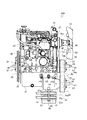
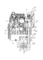
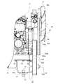
図2、図3に示すように、エンジン105は、下部にオイルパン21を備え、このオイルパン21の上部にシリンダブロック22を備え、このシリンダブロック22の上部にシリンダヘッド23を備えている。
Next, the engine 105 according to the first embodiment of the present invention will be described with reference to FIGS.
As shown in FIGS. 2 and 3, the engine 105 includes an oil pan 21 at a lower portion, a cylinder block 22 at an upper portion of the oil pan 21, and a cylinder head 23 at an upper portion of the cylinder block 22.

シリンダブロック22内には、クランク軸24が前後水平方向に架設され、このクランク軸24の前後端部は、シリンダブロック22の前後面からそれぞれ突出している。クランク軸24の後端部には、フライホイル25が固設されているとともに、クランク軸24の前端部には、前方から順に第一クランクプーリ24a、第二クランクプーリ24bが固設されている。   A crankshaft 24 is installed in the front and rear horizontal direction in the cylinder block 22, and front and rear end portions of the crankshaft 24 protrude from front and rear surfaces of the cylinder block 22, respectively. A flywheel 25 is fixed to the rear end portion of the crankshaft 24, and a first crank pulley 24a and a second crank pulley 24b are fixed to the front end portion of the crankshaft 24 in order from the front. .

そして、クランク軸24の上方には、冷却ファン13が配置され、この冷却ファン13のファン軸26には、プーリ26aが固設されているとともに、冷却水ポンプ27が取り付けられている。冷却ファン13の右方には、オルタネータ28が配置され、このオルタネータ28のオルタネータ軸29には、プーリ29aが固設されている。   The cooling fan 13 is disposed above the crankshaft 24. A pulley 26a is fixed to the fan shaft 26 of the cooling fan 13, and a cooling water pump 27 is attached thereto. An alternator 28 is disposed on the right side of the cooling fan 13, and a pulley 29 a is fixed to an alternator shaft 29 of the alternator 28.

そして、クランク軸24の第二クランクプーリ24b、ファン軸26のプーリ26a、オルタネータ軸29のプーリ29aに、一本のベルト30が巻回されて補機駆動用ベルト機構53が構成されており、このベルト30を介してクランク軸24からの動力が伝達されて、冷却ファン13、冷却水ポンプ27、オルタネータ28が駆動される。   A single belt 30 is wound around the second crank pulley 24b of the crankshaft 24, the pulley 26a of the fan shaft 26, and the pulley 29a of the alternator shaft 29 to form an accessory drive belt mechanism 53. The power from the crankshaft 24 is transmitted via the belt 30, and the cooling fan 13, the cooling water pump 27, and the alternator 28 are driven.

また、シリンダヘッド23の前面側には、燃料噴射ポンプ31やカム軸(図示省略)を駆動するギヤ群(図示省略)を内装するギヤケース32が配置されている。   A gear case 32 that houses a gear group (not shown) for driving the fuel injection pump 31 and the camshaft (not shown) is disposed on the front side of the cylinder head 23.

また、オイルパン21の前部下側には、切欠き部21aが形成されている。切欠き部21aは、オイルパン21の前下角部が側面視略矩形状に切り欠かれて形成される空間であり、この切欠き部21a内に動力伝達ケースとなるギヤボックス41が配置されている。   Further, a notch 21 a is formed on the lower side of the front portion of the oil pan 21. The notch 21a is a space formed by cutting the front lower corner of the oil pan 21 into a substantially rectangular shape in a side view, and a gear box 41 serving as a power transmission case is disposed in the notch 21a. Yes.

ギヤボックス41は、オイルパン21の切欠き部21a内の左右略中央部に配置されている。つまり、ギヤボックス41は、エンジン105の左右略中央部に配置されている。ギヤボックス41は、クランク軸24からの動力がベルト機構33を介して入力される入力軸34と、この入力軸34からの動力を出力する第一出力軸35と、この第一出力軸35に入力軸34の動力を伝達するベベルギヤ36(図5参照)と、を内装している。   The gear box 41 is disposed at a substantially central portion on the left and right sides in the cutout portion 21 a of the oil pan 21. That is, the gear box 41 is disposed at the substantially right and left central portion of the engine 105. The gear box 41 includes an input shaft 34 to which power from the crankshaft 24 is input via the belt mechanism 33, a first output shaft 35 that outputs power from the input shaft 34, and the first output shaft 35. A bevel gear 36 (see FIG. 5) for transmitting the power of the input shaft 34 is internally provided.

入力軸34は、クランク軸24の下方で、クランク軸24に対して平行(前後水平方向)に配置されている。入力軸34は、ギヤボックス41前部から突出するようにギヤボックス41に内装され、ギヤボックス41に軸受けを介して回動可能に支持されている(図5参照)。   The input shaft 34 is disposed below the crankshaft 24 and parallel to the crankshaft 24 (front-rear horizontal direction). The input shaft 34 is housed in the gear box 41 so as to protrude from the front portion of the gear box 41, and is rotatably supported by the gear box 41 via a bearing (see FIG. 5).

入力軸34の前端部には、入力プーリ34aが固設されている。入力プーリ34aの後側には、冷却ファン42(図5参照)が取り付けられており、後方に向かって冷却風を送風して、オイルパン21などを効率良く冷却できる。   An input pulley 34 a is fixed to the front end portion of the input shaft 34. A cooling fan 42 (see FIG. 5) is attached to the rear side of the input pulley 34a, and the cooling fan can be blown toward the rear to efficiently cool the oil pan 21 and the like.

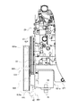
図4に示すように、入力軸34の入力プーリ34aとクランク軸24の第一クランクプーリ24aに、ベルト39が巻回されてベルト機構33が構成されている。ベルト39の内周側には、ベルト39に張力を付与するテンション部材となるテンションプーリ40が当接されている。テンションプーリ40は、バネなどの弾性部材(図示省略)によって右方に付勢されて、ベルト39に張力を付与している。テンションプーリ40は、ブラケット55を介してシリンダブロック22などに取り付けられている。ブラケット55には、長孔55aが左右方向に開口されており、この長孔55a内にテンションプーリ40のプーリ軸40aが摺動自在に配置されている。   As shown in FIG. 4, a belt mechanism 33 is configured by winding a belt 39 around an input pulley 34 a of the input shaft 34 and a first crank pulley 24 a of the crankshaft 24. A tension pulley 40 serving as a tension member that applies tension to the belt 39 is in contact with the inner peripheral side of the belt 39. The tension pulley 40 is urged to the right by an elastic member (not shown) such as a spring to apply tension to the belt 39. The tension pulley 40 is attached to the cylinder block 22 or the like via a bracket 55. A long hole 55a is opened in the left-right direction in the bracket 55, and the pulley shaft 40a of the tension pulley 40 is slidably disposed in the long hole 55a.

図2、図3に示すように、第一出力軸35は、クランク軸24に対して垂直(上下方向)に配置されている。つまり、第一出力軸35は、入力軸34に対しても垂直に配置されている。第一出力軸35は、ギヤボックス41の左右略中央部に配置されているとともに、エンジン105の前後範囲内に配置されている。つまり、第一出力軸35は、平面視においてエンジン105の投影範囲内に配置されている。第一出力軸35は、ギヤボックス41下部から突出するようにギヤボックス41に内装され、ギヤボックス41に軸受けを介して回動可能に支持されている(図5参照)。   As shown in FIGS. 2 and 3, the first output shaft 35 is disposed vertically (up and down direction) with respect to the crankshaft 24. That is, the first output shaft 35 is also arranged perpendicular to the input shaft 34. The first output shaft 35 is disposed at a substantially right and left central portion of the gear box 41 and is disposed within the front-rear range of the engine 105. That is, the first output shaft 35 is disposed within the projection range of the engine 105 in plan view. The first output shaft 35 is housed in the gear box 41 so as to protrude from the lower portion of the gear box 41, and is rotatably supported by the gear box 41 via a bearing (see FIG. 5).

図5に示すように、ベベルギヤ36は、入力軸34の動力を第一出力軸35に伝達するためのものである。ギヤボックス41内では、入力軸34の端部(後端部)に一方のベベルギヤ36が固設され、このベベルギヤ36に噛合する他方のベベルギヤ36が第一出力軸35の端部(上端部)に固設されている。   As shown in FIG. 5, the bevel gear 36 is for transmitting the power of the input shaft 34 to the first output shaft 35. In the gear box 41, one bevel gear 36 is fixed to the end portion (rear end portion) of the input shaft 34, and the other bevel gear 36 that meshes with the bevel gear 36 is the end portion (upper end portion) of the first output shaft 35. Is fixed.

第一出力軸35の下端部には、第一出力部材となる第一出力プーリ35aがキー嵌合により固定されているとともに、第一出力軸35の同軸上に第二出力軸37が着脱可能に連結されている。   A first output pulley 35 a serving as a first output member is fixed to the lower end portion of the first output shaft 35 by key fitting, and a second output shaft 37 is detachable on the same axis as the first output shaft 35. It is connected to.

第二出力軸37には、第二出力部材となる第二出力プーリ37aが電磁クラッチ38を介して設けられている。電磁クラッチ38は、第二出力軸37から第二出力プーリ37aへの動力の伝達・遮断を切り替えるクラッチとなるものである。なお、クラッチは、電磁クラッチ38に限定するものではなく、例えば、油圧クラッチなどでもよい。   The second output shaft 37 is provided with a second output pulley 37 a serving as a second output member via an electromagnetic clutch 38. The electromagnetic clutch 38 is a clutch that switches between transmission and interruption of power from the second output shaft 37 to the second output pulley 37a. The clutch is not limited to the electromagnetic clutch 38, and may be a hydraulic clutch, for example.

このような構成で、エンジン105のクランク軸24の動力は、図1から図3に示すように、第一クランクプーリ24a、ベルト39、入力プーリ34a、入力軸34、ベベルギヤ36、第一出力軸35に伝達される。そして、第一出力軸35の動力は、第一出力プーリ35a、ベルト82、プーリ83a、入力軸83に伝達されて前記油圧ポンプ(図示省略)が駆動される。また、第一出力軸35の動力は、第二出力軸37、第二出力プーリ37a、ベルト81、入力プーリ6a、入力軸6に伝達されてモア7の回転刃7aが駆動される。   With such a configuration, the power of the crankshaft 24 of the engine 105 is, as shown in FIGS. 1 to 3, the first crank pulley 24a, the belt 39, the input pulley 34a, the input shaft 34, the bevel gear 36, the first output shaft. 35. The power of the first output shaft 35 is transmitted to the first output pulley 35a, the belt 82, the pulley 83a, and the input shaft 83 to drive the hydraulic pump (not shown). The power of the first output shaft 35 is transmitted to the second output shaft 37, the second output pulley 37a, the belt 81, the input pulley 6a, and the input shaft 6 to drive the rotary blade 7a of the mower 7.

図6に示すように、ギヤボックス41下部の左右側面には、電磁クラッチ38を取り付けるためのボス部54が設けられている。ボス部54の内周面には、ネジ溝が形成されている。電磁クラッチ38には、平面視においてボス部54と重なる位置にボルト孔38aが穿設されている。   As shown in FIG. 6, boss portions 54 for attaching the electromagnetic clutch 38 are provided on the left and right side surfaces of the lower portion of the gear box 41. A screw groove is formed on the inner peripheral surface of the boss portion 54. The electromagnetic clutch 38 has a bolt hole 38a at a position overlapping the boss portion 54 in plan view.

このような構成で、ギヤボックス41のボス部54と電磁クラッチ38のボルト孔38aとを平面視において一致させた状態で、ボルト孔38aの下方からボルト44を螺挿することにより、電磁クラッチ38をギヤボックス41に取り付けることができる。   With such a configuration, the bolt 44 is screwed from below the bolt hole 38a in a state where the boss portion 54 of the gear box 41 and the bolt hole 38a of the electromagnetic clutch 38 are aligned in plan view, whereby the electromagnetic clutch 38 is inserted. Can be attached to the gear box 41.

図7、図8に示すように、ギヤボックス41の上部には、取付部43が設けられており、この取付部43を介してギヤボックス41がボルト145によってオイルパン21に取り付けられる。取付部43は、ギヤボックス41の上部に固定(あるいはギヤボックス41と一体的に成型)され、左右両端部が正面視においてギヤボックス41の左右両側面から突出している。取付部43の左右両端部には、それぞれ複数(本実施例では左右片側に3孔ずつ)のボルト孔43aが前後方向に適宜間隔で穿設されている。一方、切欠き部21a内のオイルパン21下面の左右両側には、平面視において取付部43のボルト孔43aと重なる位置にボルト孔146が複数(ボルト孔43aと同数)穿設されている。ボルト孔146は、オイルパン21の下面から上方にオイルパン21の中途部(オイルパン21を貫通しない程度)まで穿設されている。   As shown in FIGS. 7 and 8, an attachment portion 43 is provided on the upper portion of the gear box 41, and the gear box 41 is attached to the oil pan 21 with a bolt 145 through the attachment portion 43. The mounting portion 43 is fixed to the upper portion of the gear box 41 (or molded integrally with the gear box 41), and both left and right end portions protrude from the left and right side surfaces of the gear box 41 in a front view. A plurality of bolt holes 43a (three holes on each of the left and right sides in this embodiment) are formed in the left and right ends of the mounting portion 43 at appropriate intervals in the front-rear direction. On the other hand, a plurality of bolt holes 146 (the same number as the bolt holes 43a) are formed on the left and right sides of the lower surface of the oil pan 21 in the notch 21a at positions overlapping the bolt holes 43a of the mounting portion 43 in plan view. The bolt hole 146 is drilled upward from the lower surface of the oil pan 21 to the middle part of the oil pan 21 (to the extent that the oil pan 21 does not penetrate).

このような構成で、ギヤボックス41を切欠き部21a内に配置して、取付部43のボルト孔43aとオイルパン21のボルト孔146とを一致させた状態で、ボルト145をボルト孔43aの下方から螺挿することにより、ギヤボックス41をオイルパン21に取り付けることができる。ギヤボックス41は、複数(本実施例では左右片側に3本ずつ)のボルト145によってオイルパン21に、確実かつ着脱可能に取り付けられる。   With such a configuration, the gear box 41 is disposed in the notch 21a and the bolt hole 145 of the bolt hole 43a is aligned with the bolt hole 43a of the mounting part 43 and the bolt hole 146 of the oil pan 21. The gear box 41 can be attached to the oil pan 21 by screwing from below. The gear box 41 is securely and detachably attached to the oil pan 21 with a plurality of bolts 145 (three on each side in the present embodiment).

ここで、図9に示すように、第一実施例に係るエンジン105では、クランク軸24前端部の前方から第一クランクプーリ24a、第二クランクプーリ24bの順に配置されている。つまり、第一クランクプーリ24aは、第二クランクプーリ24bよりも外側に配置されて、エンジン105の前側において、ベルト機構33が補機駆動用ベルト機構53よりも外側に配置されている。   Here, as shown in FIG. 9, in the engine 105 according to the first embodiment, the first crank pulley 24a and the second crank pulley 24b are arranged in this order from the front of the front end portion of the crankshaft 24. In other words, the first crank pulley 24 a is disposed outside the second crank pulley 24 b, and the belt mechanism 33 is disposed outside the accessory driving belt mechanism 53 on the front side of the engine 105.

以上のように、本発明の第一実施例に係るエンジン105は、略水平方向にクランク軸24を有するエンジン105であって、クランク軸24の下方で、クランク軸24に対して平行に配置し、ベルト機構33を介してクランク軸24からの動力を受ける入力軸34と、入力軸34からの動力を出力し、クランク軸24に対して垂直に配置する第一出力軸35と、第一出力軸35に入力軸34の動力を伝達するベベルギヤ36と、を内装するギヤボックス41を備えるものである。   As described above, the engine 105 according to the first embodiment of the present invention is the engine 105 having the crankshaft 24 in the substantially horizontal direction, and is disposed below the crankshaft 24 and in parallel with the crankshaft 24. The input shaft 34 that receives power from the crankshaft 24 via the belt mechanism 33, the first output shaft 35 that outputs the power from the input shaft 34, and is arranged perpendicular to the crankshaft 24, and the first output A gear box 41 having a bevel gear 36 for transmitting the power of the input shaft 34 to the shaft 35 is provided.

このような構成により、ギヤボックス41をコンパクトに構成して、エンジン105がコンパクトになるため、車両の小型化が容易である。そして、ギヤボックス41を予めエンジン105に取り付けて、モジュール化できるため、取付作業の効率性が向上する。   With such a configuration, the gear box 41 is configured to be compact and the engine 105 is compact, so that the vehicle can be easily downsized. Since the gear box 41 can be pre-mounted on the engine 105 and modularized, the efficiency of the mounting work is improved.

また、第一出力軸35を平面視においてエンジン105の投影範囲内に配置するものである。   Further, the first output shaft 35 is disposed within the projection range of the engine 105 in plan view.

このような構成により、第一出力軸35をコンパクトに配置して、エンジン105がコンパクトになるため、車両の小型化が容易である。   With such a configuration, the first output shaft 35 is arranged compactly, and the engine 105 becomes compact, so that the vehicle can be easily downsized.

また、エンジン105下部にオイルパン21を備え、オイルパン21にギヤボックス41を取り付けるものである。   An oil pan 21 is provided at the lower part of the engine 105, and a gear box 41 is attached to the oil pan 21.

このような構成により、オイルパン21を利用してギヤボックス41を簡単にエンジン105に取り付けることができるため、取付作業の効率性が向上する。そして、ギヤボックス41がエンジン105と同一振動系となることにより、防振対策を簡素化できるため、コストダウンが容易である。   With such a configuration, the gear box 41 can be easily attached to the engine 105 using the oil pan 21, so that the efficiency of the attaching operation is improved. Since the gear box 41 has the same vibration system as that of the engine 105, the anti-vibration measures can be simplified, so that the cost can be easily reduced.

また、オイルパン21下側に切欠き部21aを形成し、切欠き部21a内にギヤボックス41を配置するものである。   Further, a notch 21a is formed below the oil pan 21, and the gear box 41 is disposed in the notch 21a.

このような構成により、ギヤボックス41をコンパクトに配置して、エンジン105がコンパクトになるため、車両の小型化が容易である。   With such a configuration, the gear box 41 is arranged in a compact manner, and the engine 105 becomes compact. Therefore, the vehicle can be easily downsized.

また、第一出力軸35に動力出力用の第一出力プーリ35aを設けるとともに、第一出力軸35の同軸上に第一出力軸35の動力を受ける第二出力軸37を連結し、第二出力軸37に動力出力用の第二出力プーリ37aを設けるものである。   The first output shaft 35 is provided with a first output pulley 35a for power output, and a second output shaft 37 receiving the power of the first output shaft 35 is connected on the same axis as the first output shaft 35. The output shaft 37 is provided with a second output pulley 37a for power output.

このような構成により、第一・第二出力プーリ35a・37aを別個の駆動対象に連結して、第一・第二出力軸35・37が複数の駆動対象に出力できるため、エンジン105の利便性が向上する。   With such a configuration, the first and second output pulleys 35a and 37a are connected to separate driving objects, and the first and second output shafts 35 and 37 can output to a plurality of driving objects. Improves.

また、第二出力プーリ37aと第二出力軸37との間に電磁クラッチ38を介設するものである。   In addition, an electromagnetic clutch 38 is interposed between the second output pulley 37 a and the second output shaft 37.

このような構成により、複数の駆動対象に出力可能なエンジン105が、その駆動対象の内少なくとも一つへの動力の伝達・遮断が切替可能となるため、エンジン105の利便性が向上する。   With such a configuration, the engine 105 that can output to a plurality of driving objects can be switched between transmission and interruption of power to at least one of the driving objects, and the convenience of the engine 105 is improved.

また、ギヤボックス41には、電磁クラッチ38が取付可能である。   An electromagnetic clutch 38 can be attached to the gear box 41.

このような構成により、電磁クラッチ38がエンジン105と同一振動系となることにより、防振対策を簡素化できるため、コストダウンが容易である。   With such a configuration, since the electromagnetic clutch 38 is in the same vibration system as the engine 105, the anti-vibration measures can be simplified, and the cost can be easily reduced.

また、前記第一動力伝達手段をベルト機構33とするものである。   Further, the first power transmission means is a belt mechanism 33.

このような構成により、ベルト機構という簡単な動力伝達手段にて、クランク軸24の動力を入力軸34に伝達できるため、コストダウンが容易であるとともに、動力伝達手段の組立作業の効率性が向上する。   With such a configuration, the power of the crankshaft 24 can be transmitted to the input shaft 34 by a simple power transmission means called a belt mechanism, so that the cost can be easily reduced and the efficiency of the assembly work of the power transmission means is improved. To do.

また、エンジン105は、ベルト機構33のベルト39に張力を付与するテンションプーリ40を備えるものである。   The engine 105 includes a tension pulley 40 that applies tension to the belt 39 of the belt mechanism 33.

このような構成により、ベルト39に張力が付与されて、ベルト39の張力を調整する手間が省けるため、エンジン105の利便性が向上する。   With such a configuration, the tension is applied to the belt 39 and the labor for adjusting the tension of the belt 39 can be saved, so that the convenience of the engine 105 is improved.

また、入力軸34は、冷却ファン42を備えるものである。   The input shaft 34 includes a cooling fan 42.

このような構成により、冷却風を送風して、エンジン105を効率良く冷却できる。   With such a configuration, the engine 105 can be efficiently cooled by blowing cooling air.

また、エンジン105は、略水平方向に配置するクランク軸24と、クランク軸24の上方で、エンジン105の前側に配置するエンジン冷却用の冷却ファン13と、エンジン105の前側に配置し、冷却ファン13にクランク軸24の動力を伝達する補機駆動用ベルト機構53と、を備えるエンジン105であって、クランク軸24の下方で、クランク軸24に対して平行に配置する入力軸34と、入力軸34からの動力を出力し、クランク軸24に対して垂直に配置する第一出力軸35と、エンジン105の前側に配置し、入力軸34にクランク軸24の動力を伝達するベルト機構33と、を備え、ベルト機構33を補機駆動用ベルト機構53よりも外側に配置するものである。   The engine 105 is disposed in a substantially horizontal direction, the crankshaft 24 disposed in a substantially horizontal direction, the cooling fan 13 for cooling the engine disposed in front of the engine 105 above the crankshaft 24, and the cooling fan disposed in front of the engine 105. 13 is an engine 105 including an auxiliary machine driving belt mechanism 53 for transmitting the power of the crankshaft 24 to the input shaft 34, an input shaft 34 disposed below the crankshaft 24 and parallel to the crankshaft 24, and an input A first output shaft 35 that outputs power from the shaft 34 and is disposed perpendicular to the crankshaft 24; a belt mechanism 33 that is disposed on the front side of the engine 105 and transmits the power of the crankshaft 24 to the input shaft 34; , And the belt mechanism 33 is disposed on the outer side of the auxiliary mechanism driving belt mechanism 53.

このような構成により、ベルト機構33のベルト39を短くできることにより、エンジン105がコンパクトになるため、車両の小型化が容易であるとともに、ベルト39の巻回が容易であるため、作業効率が向上する。そして、ベルト機構33は、補機駆動用ベルト機構53よりも外側に位置することにより、ベルト39の取り外しが容易であるため、エンジン105の利便性が向上する。   With such a configuration, the belt 39 of the belt mechanism 33 can be shortened, so that the engine 105 becomes compact, so that the vehicle can be easily downsized and the belt 39 can be easily wound, so that the working efficiency is improved. To do. Since the belt mechanism 33 is positioned outside the auxiliary device driving belt mechanism 53, the belt 39 can be easily detached, so that the convenience of the engine 105 is improved.

次に、本発明の第二実施例に係るエンジン205について、図10から図12により説明する。なお、図10から図12において、第一実施例と同一符号の部材は第一実施例と同一構成であるため詳細な説明は省略する。   Next, an engine 205 according to a second embodiment of the present invention will be described with reference to FIGS. 10 to 12, members having the same reference numerals as those in the first embodiment have the same configurations as those in the first embodiment, and thus detailed description thereof is omitted.

第二実施例に係るエンジン205は、第一実施例に係るエンジン105に対して以下の点で相違する。すなわち、図10から図12に示すように、第二実施例に係るエンジン205では、ギヤボックス41は、取付部43の下面からシリンダブロック22まで到達する長さを有するボルト245によって、シリンダブロック22にオイルパン21と共締めして取り付けられている。切欠き部21a内のオイルパン21下面の左右両側には、平面視において取付部43のボルト孔43aと重なる位置にボルト孔246が穿設されている。ボルト孔246は、オイルパン21の下面から上方にオイルパン21を貫通してシリンダブロック22まで到達するように穿設されている。そして、シリンダブロック22の左右両側に、平面視においてオイルパン21のボルト孔246と重なる位置にボルト孔247が穿設されている。   The engine 205 according to the second embodiment is different from the engine 105 according to the first embodiment in the following points. That is, as shown in FIGS. 10 to 12, in the engine 205 according to the second embodiment, the gear box 41 is connected to the cylinder block 22 by the bolt 245 having a length reaching the cylinder block 22 from the lower surface of the mounting portion 43. Are attached together with the oil pan 21. Bolt holes 246 are formed on the left and right sides of the lower surface of the oil pan 21 in the notch 21a at positions overlapping the bolt holes 43a of the mounting portion 43 in plan view. The bolt hole 246 is formed so as to penetrate the oil pan 21 upward from the lower surface of the oil pan 21 and reach the cylinder block 22. Bolt holes 247 are formed on the left and right sides of the cylinder block 22 at positions overlapping the bolt holes 246 of the oil pan 21 in plan view.

このような構成で、ギヤボックス41を切欠き部21a内に配置して、取付部43のボルト孔43aとオイルパン21のボルト孔246とシリンダブロック22のボルト孔247とを一致させた状態で、ボルト245をボルト孔43aの下方から螺挿することにより、ギヤボックス41をシリンダブロック22にオイルパン21と共締めして取り付けることができる。ギヤボックス41は、複数(本実施例では左右片側に3本ずつ)のボルト245によってシリンダブロック22に、確実かつ着脱可能に取り付けられる。   With such a configuration, the gear box 41 is disposed in the notch 21a, and the bolt hole 43a of the mounting part 43, the bolt hole 246 of the oil pan 21, and the bolt hole 247 of the cylinder block 22 are made to coincide with each other. The gear box 41 can be attached to the cylinder block 22 together with the oil pan 21 by screwing the bolt 245 from below the bolt hole 43a. The gear box 41 is securely and detachably attached to the cylinder block 22 by a plurality of bolts 245 (three in each of the left and right sides in this embodiment).

以上のように、本発明の第二実施例に係るエンジン205は、エンジン205下部にオイルパン21を備え、ギヤボックス41をエンジン205のシリンダブロック22にオイルパン21と共締めして取り付けるものである。   As described above, the engine 205 according to the second embodiment of the present invention includes the oil pan 21 at the lower part of the engine 205, and the gear box 41 is attached to the cylinder block 22 of the engine 205 together with the oil pan 21. is there.

このような構成により、ギヤボックス41とオイルパン21とを一度にシリンダブロック22に取り付けることができるため、取付作業の効率性が向上する。そして、ギヤボックス41を剛性の高いシリンダブロック22に取り付けるため、取り付けの確実性が向上する。また、ギヤボックス41がエンジン205と同一振動系となることにより、防振対策を簡素化できるため、コストダウンが容易である。   With such a configuration, since the gear box 41 and the oil pan 21 can be attached to the cylinder block 22 at a time, the efficiency of the attaching operation is improved. And since the gear box 41 is attached to the cylinder block 22 with high rigidity, the certainty of attachment improves. Further, since the gear box 41 has the same vibration system as that of the engine 205, the anti-vibration measures can be simplified, so that cost reduction is easy.

次に、本発明の第三実施例に係るエンジン305について、図13、図14により説明する。なお、図13、図14において、第一実施例と同一符号の部材は第一実施例と同一構成であるため詳細な説明は省略する。   Next, an engine 305 according to a third embodiment of the present invention will be described with reference to FIGS. In FIGS. 13 and 14, members having the same reference numerals as those in the first embodiment have the same configurations as those in the first embodiment, and thus detailed description thereof is omitted.

第三実施例に係るエンジン305は、第一実施例に係るエンジン105に対して以下の点で相違する。すなわち、図13、図14に示すように、第三実施例に係るエンジン305では、ギヤボックス41は、オイルパン21の前下角部に配置され、オイルパン21とギヤボックス41とが一体的に成型されている。オイルパン21の内部とギヤボックス41の内部とは、隔壁50によって仕切られており、オイルパン21からギヤボックス41への油の流入を防止している。   The engine 305 according to the third embodiment is different from the engine 105 according to the first embodiment in the following points. That is, as shown in FIGS. 13 and 14, in the engine 305 according to the third embodiment, the gear box 41 is disposed at the lower front corner of the oil pan 21, and the oil pan 21 and the gear box 41 are integrally formed. Molded. The inside of the oil pan 21 and the inside of the gear box 41 are partitioned by a partition wall 50 to prevent oil from flowing from the oil pan 21 into the gear box 41.

以上のように、本発明の第三実施例に係るエンジン305は、エンジン305下部にオイルパン21を備え、オイルパン21とギヤボックス41を一体的に成型するものである。   As described above, the engine 305 according to the third embodiment of the present invention includes the oil pan 21 at the lower portion of the engine 305, and the oil pan 21 and the gear box 41 are integrally molded.

このような構成により、ギヤボックス41とオイルパン21とが一体となることにより、ギヤボックス41の取付作業を省略できるため、取付作業の効率性が向上するとともに、部品点数が少なくなるため、コストダウンが容易である。そして、ギヤボックス41がエンジン305と同一振動系となることにより、防振対策を簡素化できるため、コストダウンが容易である。   With such a configuration, since the gear box 41 and the oil pan 21 are integrated, the mounting operation of the gear box 41 can be omitted, so that the efficiency of the mounting operation is improved and the number of parts is reduced. Easy to down. Since the gear box 41 has the same vibration system as that of the engine 305, the anti-vibration measures can be simplified, so that the cost can be easily reduced.

次に、本発明の第四実施例に係るエンジン405について、図15から図17により説明する。なお、図15から図17において、第一実施例と同一符号の部材は第一実施例と同一構成であるため詳細な説明は省略する。   Next, an engine 405 according to a fourth embodiment of the present invention will be described with reference to FIGS. 15 to 17, members having the same reference numerals as those in the first embodiment have the same configurations as those in the first embodiment, and thus detailed description thereof is omitted.

第四実施例に係るエンジン405は、第一実施例に係るエンジン105に対して以下の点で相違する。すなわち、図15、図16に示すように、第四実施例に係るエンジン405では、クランク軸24の前後端部にそれぞれPTO軸45・46が設けられているとともに、入力軸34の前端部にPTO軸47が設けられている。   The engine 405 according to the fourth embodiment is different from the engine 105 according to the first embodiment in the following points. That is, as shown in FIGS. 15 and 16, in the engine 405 according to the fourth embodiment, the PTO shafts 45 and 46 are respectively provided at the front and rear end portions of the crankshaft 24, and at the front end portion of the input shaft 34. A PTO shaft 47 is provided.

PTO軸45・46・47は、いずれも動力取出用の軸となるものであり、PTO軸45・46は、クランク軸24の同軸上に配置され、PTO軸47は、入力軸34の同軸上に配置されている。PTO軸45・46・47は、それぞれ板状部材である取付プレート56に突設されている。なお、PTO軸45・46・47の構成は、略同一であることから、ここではクランク軸24の前端部に連結されているPTO軸45を例として説明し、PTO軸46・47については詳細な説明を省略する。   The PTO shafts 45, 46, and 47 are all shafts for power extraction. The PTO shafts 45 and 46 are arranged on the same axis as the crankshaft 24, and the PTO shaft 47 is on the same axis as the input shaft 34. Is arranged. Each of the PTO shafts 45, 46, and 47 protrudes from a mounting plate 56 that is a plate-like member. Since the PTO shafts 45, 46 and 47 have substantially the same configuration, the PTO shaft 45 connected to the front end of the crankshaft 24 will be described as an example here, and the PTO shafts 46 and 47 will be described in detail. The detailed explanation is omitted.

図16に示すように、取付プレート56には、PTO軸45の周囲に複数のボルト孔56aが穿設されている。一方、第一クランクプーリ24aには、正面視において取付プレート56のボルト孔56aと重なる位置に複数のボルト孔(図示省略)が穿設されている。このような構成で、PTO軸45・46をクランク軸24前後端部の同軸上に配置し、PTO軸47を入力軸34前端部の同軸上に配置し、第一クランクプーリ24a、フライホイル25、入力プーリ34aのボルト孔と、取付プレート56のボルト孔56aとをそれぞれ一致させた状態で、ボルト57をボルト孔56aに螺挿することにより、取付プレート56を介してPTO軸45・46・47をそれぞれ第一クランクプーリ24a、フライホイル25、入力プーリ34aに取り付けることができる。なお、PTO軸45・46・47とそれぞれの軸とを連結する構成は、本実施例に限定するものではなく、例えば、カップリングにより連結する構成などでもよい。   As shown in FIG. 16, the mounting plate 56 has a plurality of bolt holes 56 a around the PTO shaft 45. On the other hand, the first crank pulley 24a has a plurality of bolt holes (not shown) at positions overlapping the bolt holes 56a of the mounting plate 56 in a front view. With such a configuration, the PTO shafts 45 and 46 are arranged coaxially at the front and rear end portions of the crankshaft 24, the PTO shaft 47 is arranged coaxially at the front end portion of the input shaft 34, the first crank pulley 24a, the flywheel 25 The bolt hole 57 of the input pulley 34a and the bolt hole 56a of the mounting plate 56 are aligned with each other, and the bolt 57 is screwed into the bolt hole 56a, so that the PTO shafts 45, 46,. 47 can be attached to the first crank pulley 24a, the flywheel 25, and the input pulley 34a, respectively. In addition, the structure which connects PTO shaft 45 * 46 * 47 and each axis | shaft is not limited to a present Example, For example, the structure etc. which are connected by coupling may be sufficient.

また、PTO軸45・46・47は、次のように構成することもできる。すなわち、図17に示すようように、クランク軸24前端部には、PTO軸45が一体的に成型されているとともに、スプライン嵌合などにより第一クランクプーリ24aが固定されている。そして、第一クランクプーリ24a内側のクランク軸24には、段差部58が形成されている。段差部58は、クランク軸24の外径が大きく形成されており、第一クランクプーリ24aの内方への移動を規制している。また、第一クランクプーリ24a外側のクランク軸24には、溝部59が形成されているとともに、この溝部59内に止め輪60が嵌め入れられており、第一クランクプーリ24aの外方への移動を規制している。   Further, the PTO shafts 45, 46 and 47 can be configured as follows. That is, as shown in FIG. 17, a PTO shaft 45 is integrally formed at the front end portion of the crankshaft 24, and the first crank pulley 24a is fixed by spline fitting or the like. A stepped portion 58 is formed on the crankshaft 24 inside the first crank pulley 24a. The stepped portion 58 is formed with a large outer diameter of the crankshaft 24 and restricts the inward movement of the first crank pulley 24a. Further, a groove 59 is formed in the crankshaft 24 outside the first crank pulley 24a, and a retaining ring 60 is fitted in the groove 59, so that the first crank pulley 24a moves outward. Is regulated.

以上のように、本発明の第四実施例に係るエンジン405は、クランク軸24および入力軸34の同軸上に動力取出用のPTO軸45・46・47を設けるものである。   As described above, the engine 405 according to the fourth embodiment of the present invention is provided with the PTO shafts 45, 46, and 47 for power extraction on the same axis as the crankshaft 24 and the input shaft 34.

このような構成により、作業機などの動力を取出可能となるため、エンジン405の利便性が向上する。   With such a configuration, it becomes possible to take out the power of the work machine and the like, and the convenience of the engine 405 is improved.

次に、本発明の第五実施例に係るエンジン505について、図18から図20により説明する。なお、図18から図20において、第一実施例と同一符号の部材は第一実施例と同一構成であるため詳細な説明は省略する。   Next, an engine 505 according to a fifth embodiment of the present invention will be described with reference to FIGS. 18 to 20, members having the same reference numerals as those in the first embodiment have the same configurations as those in the first embodiment, and thus detailed description thereof is omitted.

第五実施例に係るエンジン505は、第一実施例に係るエンジン105に対して以下の点で相違する。すなわち、図18から図20に示すように、第五実施例に係るエンジン505では、クランク軸524の前端部に前方から順に第二クランクプーリ524b、第一クランクプーリ524aが固設されている。つまり、第一クランクプーリ524aは、第二クランクプーリ524bよりも内側に配置されている。   The engine 505 according to the fifth embodiment is different from the engine 105 according to the first embodiment in the following points. That is, as shown in FIGS. 18 to 20, in the engine 505 according to the fifth embodiment, the second crank pulley 524b and the first crank pulley 524a are fixed to the front end portion of the crankshaft 524 in order from the front. That is, the first crank pulley 524a is disposed on the inner side than the second crank pulley 524b.

そして、クランク軸524の第二クランクプーリ524b、ファン軸26のプーリ26a、オルタネータ軸29のプーリ29aに、一本のベルト530が巻回されて補機駆動用ベルト機構553が構成されているとともに、この補機駆動用ベルト機構553よりも内側で、入力軸34の入力プーリ34aとクランク軸524の第一クランクプーリ524aに、ベルト539が巻回されてベルト機構533が構成されている。図20に示すように、ベルト539の内周側には、ベルト539に張力を付与するテンションプーリ540が当接されている。テンションプーリ540は、バネなどの弾性部材(図示省略)によって右方に付勢されて、ベルト539に張力を付与している。テンションプーリ540は、ブラケット55を介してシリンダブロック22などに取り付けられている。ブラケット55には、長孔55aが左右方向に開口されており、この長孔55a内にテンションプーリ540のプーリ軸540aが摺動自在に配置されている。   A single belt 530 is wound around the second crank pulley 524b of the crankshaft 524, the pulley 26a of the fan shaft 26, and the pulley 29a of the alternator shaft 29 to constitute an auxiliary machine driving belt mechanism 553. A belt mechanism 533 is formed by winding a belt 539 around the input pulley 34a of the input shaft 34 and the first crank pulley 524a of the crankshaft 524 on the inner side of the accessory driving belt mechanism 553. As shown in FIG. 20, a tension pulley 540 that applies tension to the belt 539 is in contact with the inner peripheral side of the belt 539. The tension pulley 540 is biased to the right by an elastic member (not shown) such as a spring to apply tension to the belt 539. The tension pulley 540 is attached to the cylinder block 22 or the like via a bracket 55. A long hole 55a is opened in the left-right direction in the bracket 55, and a pulley shaft 540a of a tension pulley 540 is slidably disposed in the long hole 55a.

以上のように、本発明の第五実施例に係るエンジン505は、略水平方向に配置するクランク軸524と、クランク軸524の上方で、エンジン505の前側に配置するエンジン冷却用の冷却ファン13と、エンジン505の前側に配置し、冷却ファン13にクランク軸524の動力を伝達する補機駆動用ベルト機構553と、を備えるエンジン505であって、クランク軸524の下方で、クランク軸524に対して平行に配置する入力軸34と、入力軸34からの動力を出力し、クランク軸524に対して垂直に配置する第一出力軸35と、エンジン505の前側に配置し、入力軸34にクランク軸524の動力を伝達するベルト機構533と、を備え、ベルト機構533を補機駆動用ベルト機構553よりも内側に配置するものである。   As described above, the engine 505 according to the fifth embodiment of the present invention includes the crankshaft 524 disposed in a substantially horizontal direction, and the cooling fan 13 for engine cooling disposed on the front side of the engine 505 above the crankshaft 524. And an auxiliary machine driving belt mechanism 553 that is disposed on the front side of the engine 505 and transmits the power of the crankshaft 524 to the cooling fan 13, and below the crankshaft 524, An input shaft 34 disposed in parallel to the input shaft 34, a first output shaft 35 that outputs power from the input shaft 34 and disposed perpendicular to the crankshaft 524, and a front side of the engine 505 are disposed on the input shaft 34. A belt mechanism 533 for transmitting the power of the crankshaft 524, and the belt mechanism 533 is disposed on the inner side of the accessory driving belt mechanism 553.

このような構成により、ベルト機構533のベルト539を短くできることにより、エンジン505がコンパクトになるため、車両の小型化が容易であるとともに、ベルト539の巻回が容易であるため、作業効率が向上する。そして、ベルト機構533が冷却ファン13を駆動する補機駆動用ベルト機構553よりも内側に位置することにより、冷却ファン13がベルト機構533に干渉しない。これにより、冷却ファン13の位置を低くして、エンジン505をコンパクトに構成できるため、車両の小型化が容易である。   With such a configuration, the belt 539 of the belt mechanism 533 can be shortened, so that the engine 505 becomes compact, so that the vehicle can be easily downsized and the belt 539 can be easily wound, so that the working efficiency is improved. To do. Since the belt mechanism 533 is positioned on the inner side of the accessory driving belt mechanism 553 that drives the cooling fan 13, the cooling fan 13 does not interfere with the belt mechanism 533. Thereby, the position of the cooling fan 13 can be lowered and the engine 505 can be configured compactly, so that the vehicle can be easily downsized.

また、エンジン505は、ベルト機構533のベルト539に張力を付与するテンションプーリ540を備えるものである。   The engine 505 includes a tension pulley 540 that applies tension to the belt 539 of the belt mechanism 533.

このような構成により、ベルト539に張力が付与されて、ベルト539の張力を調整する手間が省けるため、エンジン505の利便性が向上する。   With such a configuration, tension is applied to the belt 539, and the labor for adjusting the tension of the belt 539 can be saved, so that the convenience of the engine 505 is improved.

次に、本発明の第六実施例に係るエンジン605について、図21から図24により説明する。なお、図21から図24において、第一実施例と同一符号の部材は第一実施例と同一構成であるため詳細な説明は省略する。   Next, an engine 605 according to a sixth embodiment of the present invention will be described with reference to FIGS. 21 to 24, members having the same reference numerals as those in the first embodiment have the same configurations as those in the first embodiment, and thus detailed description thereof is omitted.

第六実施例に係るエンジン605は、第一実施例に係るエンジン105に対して以下の点で相違する。すなわち、図21から図23に示すように、第六実施例に係るエンジン605では、クランク軸624の前端部に第二クランクプーリ624bが固設され、クランク軸624の後端部に後方から順に第1クランクプーリ624a、フライホイル25が固設されている。つまり、第1クランクプーリ624aは、フライホイル25よりも外側に配置されている。   The engine 605 according to the sixth embodiment is different from the engine 105 according to the first embodiment in the following points. That is, as shown in FIGS. 21 to 23, in the engine 605 according to the sixth embodiment, the second crank pulley 624b is fixed to the front end portion of the crankshaft 624, and the rear end portion of the crankshaft 624 is sequentially arranged from the rear. The first crank pulley 624a and the flywheel 25 are fixed. That is, the first crank pulley 624a is disposed outside the flywheel 25.

そして、オイルパン621の後部下側には、切欠き部621aが形成されている。切欠き部621aは、オイルパン621の後下角部が側面視略矩形状に切り欠かれて形成される空間であり、この切欠き部621a内にギヤボックス641が配置されている。ギヤボックス641からは、入力軸634が後方に突出し、この入力軸634の後端部には、入力プーリ634aが固設されている。つまり、入力プーリ634aは、フライホイル25よりも外側に配置されている。   A notch 621 a is formed below the rear part of the oil pan 621. The notch 621a is a space formed by cutting the rear lower corner of the oil pan 621 into a substantially rectangular shape in a side view, and the gear box 641 is disposed in the notch 621a. An input shaft 634 protrudes rearward from the gear box 641, and an input pulley 634 a is fixed to the rear end portion of the input shaft 634. That is, the input pulley 634a is disposed outside the flywheel 25.

こうして、フライホイル25よりも外側で、入力軸634の入力プーリ634aとクランク軸624の第1クランクプーリ624aに、ベルト639が巻回されてベルト機構633が構成されている。   Thus, the belt 639 is wound around the input pulley 634 a of the input shaft 634 and the first crank pulley 624 a of the crank shaft 624 outside the flywheel 25, thereby forming a belt mechanism 633.

ここで、ギヤボックス641は、ブラケット651を介してシリンダブロック22に取り付けられている。図23、図24に示すようように、ブラケット651は、背面視略台形状に形成された板状部材であり、右上部が上方に延出されてアーム部651aが形成されている。ブラケット651は、複数(本実施例では5本)のボルト652によってシリンダブロック22の後面に、確実かつ着脱可能に取り付けられている。   Here, the gear box 641 is attached to the cylinder block 22 via a bracket 651. As shown in FIGS. 23 and 24, the bracket 651 is a plate-like member formed in a substantially trapezoidal shape when viewed from the back, and an upper right portion extends upward to form an arm portion 651a. The bracket 651 is securely and detachably attached to the rear surface of the cylinder block 22 by a plurality of bolts 652 (5 in this embodiment).

そして、ブラケット651の右下部には、ギヤボックス641を取り付けるための取付孔651bが開口されている。取付孔651bは、ギヤボックス641が嵌合する形状(略円形)に形成されている。取付孔651bは、クランク軸624に対して左右一方(本実施例では右方)に偏心した位置に配置されており、これにより、フライホイル25を回避してギヤボックス641をできるだけ上方に配置して、エンジン605をコンパクトに構成できる(エンジン605の高さを低くする)ようにしている。   An attachment hole 651b for attaching the gear box 641 is opened in the lower right portion of the bracket 651. The mounting hole 651b is formed in a shape (substantially circular) into which the gear box 641 is fitted. The mounting hole 651b is arranged at a position eccentric to the left or right side (right side in this embodiment) with respect to the crankshaft 624, thereby avoiding the flywheel 25 and arranging the gear box 641 as high as possible. Thus, the engine 605 can be configured compactly (the height of the engine 605 is reduced).

また、ブラケット651の左下部には、長孔651cが左下斜め方向に開口されており、この長孔651c内にテンションプーリ640のプーリ軸640aが摺動自在に配置されている。テンションプーリ640は、ベルト639に張力を付与するテンション部材となるものであり、ベルト639の内周側に当接した状態でバネなどの弾性部材(図示省略)によって左下方に付勢されている。   Further, a long hole 651c is opened in the lower left diagonal direction at the lower left portion of the bracket 651, and a pulley shaft 640a of a tension pulley 640 is slidably disposed in the long hole 651c. The tension pulley 640 serves as a tension member that applies tension to the belt 639, and is biased to the lower left by an elastic member (not shown) such as a spring in contact with the inner peripheral side of the belt 639. .

以上のように、本発明の第六実施例に係るエンジン605は、略水平方向に配置するクランク軸624と、エンジン605の後側に配置するフライホイル25と、を備えるエンジン605であって、クランク軸624の下方で、クランク軸624に対して平行に配置する入力軸634と、入力軸634からの動力を出力し、クランク軸624に対して垂直に配置する第一出力軸35と、エンジン605の後側に配置し、入力軸634にクランク軸624の動力を伝達するベルト機構633と、を備え、ベルト機構633をフライホイル25よりも外側に配置するものである。   As described above, the engine 605 according to the sixth embodiment of the present invention is an engine 605 including the crankshaft 624 disposed in a substantially horizontal direction and the flywheel 25 disposed on the rear side of the engine 605, Below the crankshaft 624, an input shaft 634 disposed parallel to the crankshaft 624, a first output shaft 35 that outputs power from the input shaft 634 and disposed perpendicular to the crankshaft 624, and the engine And a belt mechanism 633 that transmits the power of the crankshaft 624 to the input shaft 634. The belt mechanism 633 is disposed outside the flywheel 25.

このような構成により、ベルト機構633のベルト639を短くできることにより、エンジン605がコンパクトになるため、車両の小型化が容易であるとともに、ベルト639の巻回が容易であるため、作業効率が向上する。そして、ベルト機構633は、フライホイル25よりも外側に位置することにより、ベルト639の取り外しが容易であるため、エンジン605の利便性が向上する。   With such a configuration, the belt 639 of the belt mechanism 633 can be shortened, so that the engine 605 becomes compact, so that the vehicle can be easily downsized and the belt 639 can be easily wound, so that the working efficiency is improved. To do. Since the belt mechanism 633 is positioned outside the flywheel 25, the belt 639 can be easily removed, so the convenience of the engine 605 is improved.

また、エンジン605は、ベルト機構633のベルト639に張力を付与するテンションプーリ640を備えるものである。   The engine 605 includes a tension pulley 640 that applies tension to the belt 639 of the belt mechanism 633.

このような構成により、ベルト639に張力が付与されて、ベルト639の張力を調整する手間が省けるため、エンジン605の利便性が向上する。   With such a configuration, the tension is applied to the belt 639 and the labor for adjusting the tension of the belt 639 can be saved, so that the convenience of the engine 605 is improved.

次に、本発明の第七実施例に係るエンジン705について、図25から図28により説明する。なお、図25から図28において、第一実施例と同一符号の部材は第一実施例と同一構成であるため詳細な説明は省略する。   Next, an engine 705 according to a seventh embodiment of the present invention will be described with reference to FIGS. 25 to 28, members having the same reference numerals as those in the first embodiment have the same configurations as those in the first embodiment, and thus detailed description thereof is omitted.

第七実施例に係るエンジン705は、第一実施例に係るエンジン105に対して以下の点で相違する。すなわち、図25から図27に示すように、第七実施例に係るエンジン705では、クランク軸724の前端部に第二クランクプーリ724bが固設され、クランク軸724の後端部に後方から順にフライホイル25、第1クランクプーリ724aが固設されている。つまり、第1クランクプーリ724aは、フライホイル25よりも内側に配置されている。   The engine 705 according to the seventh embodiment is different from the engine 105 according to the first embodiment in the following points. That is, as shown in FIGS. 25 to 27, in the engine 705 according to the seventh embodiment, the second crank pulley 724b is fixed to the front end portion of the crankshaft 724, and the rear end portion of the crankshaft 724 is sequentially arranged from the rear. The flywheel 25 and the first crank pulley 724a are fixed. That is, the first crank pulley 724a is disposed on the inner side than the flywheel 25.

そして、オイルパン721の後部下側には、切欠き部721aが形成されている。切欠き部721aは、オイルパン721の後下角部が側面視略矩形状に切り欠かれて形成される空間であり、この切欠き部721a内にギヤボックス741が配置されている。ギヤボックス741からは、入力軸734が後方に突出し、この入力軸734の後端部には、入力プーリ734aが固設されており、この入力プーリ734aはフライホイル25よりも内側に配置されている。   A notch 721a is formed at the lower rear side of the oil pan 721. The notch 721a is a space formed by cutting the rear lower corner of the oil pan 721 into a substantially rectangular shape in a side view, and a gear box 741 is disposed in the notch 721a. An input shaft 734 protrudes rearward from the gear box 741, and an input pulley 734 a is fixed to a rear end portion of the input shaft 734, and the input pulley 734 a is disposed inside the flywheel 25. Yes.

こうして、フライホイル25よりも内側で、入力軸734の入力プーリ734aとクランク軸724の第1クランクプーリ724aに、ベルト739が巻回されてベルト機構733が構成されている。   In this way, the belt 739 is wound around the input pulley 734 a of the input shaft 734 and the first crank pulley 724 a of the crank shaft 724 inside the flywheel 25, thereby forming a belt mechanism 733.

ここで、ギヤボックス741は、ブラケット751を介してシリンダブロック22に取り付けられている。図27、図28に示すようように、ブラケット751は、背面視略逆台形状に形成された板状部材であり、右上部が上方に延出されてアーム部751aが形成されている。ブラケット751は、複数(本実施例では5本)のボルト752によってシリンダブロック22の後面に、確実かつ着脱可能に取り付けられている。   Here, the gear box 741 is attached to the cylinder block 22 via a bracket 751. As shown in FIGS. 27 and 28, the bracket 751 is a plate-like member formed in a substantially inverted trapezoidal shape when viewed from the back, and an upper right portion extends upward to form an arm portion 751a. The bracket 751 is securely and detachably attached to the rear surface of the cylinder block 22 with a plurality of bolts 752 (5 in this embodiment).

そして、ブラケット751の下部には、ギヤボックス741を取り付けるための取付孔751bが開口されている。取付孔751bは、ギヤボックス741が嵌合する形状(略円形)に形成されている。取付孔751bは、左右中心がクランク軸724と一致する位置に配置されており、これにより、ギヤボックス741は、左右中心(入力軸434)がクランク軸724と一致する位置に配置される。   An attachment hole 751b for attaching the gear box 741 is opened at the lower portion of the bracket 751. The mounting hole 751b is formed in a shape (substantially circular) into which the gear box 741 is fitted. The mounting hole 751 b is arranged at a position where the left and right center coincides with the crankshaft 724, whereby the gear box 741 is arranged at a position where the left and right center (input shaft 434) coincides with the crankshaft 724.

また、ブラケット751の右部には、長孔751cが左右方向に開口されており、この長孔751c内にテンションプーリ740のプーリ軸740aが摺動自在に配置されている。テンションプーリ740は、ベルト739に張力を付与するテンション部材となるものであり、ベルト739の内周側に当接した状態でバネなどの弾性部材(図示省略)によって右方に付勢されている。   In addition, a long hole 751c is opened in the right and left direction on the right portion of the bracket 751, and a pulley shaft 740a of a tension pulley 740 is slidably disposed in the long hole 751c. The tension pulley 740 serves as a tension member that applies tension to the belt 739, and is biased to the right by an elastic member (not shown) such as a spring in contact with the inner peripheral side of the belt 739. .

以上のように、本発明の第七実施例に係るエンジン705は、略水平方向に配置するクランク軸724と、エンジン705の後側に配置するフライホイル25と、を備えるエンジン705であって、クランク軸724の下方で、クランク軸724に対して平行に配置する入力軸734と、入力軸734からの動力を出力し、クランク軸724に対して垂直に配置する第一出力軸35と、エンジン705の後側に配置し、入力軸734にクランク軸724の動力を伝達するベルト機構733と、を備え、ベルト機構733をフライホイル25よりも内側に配置するものである。   As described above, the engine 705 according to the seventh embodiment of the present invention is an engine 705 including the crankshaft 724 disposed in a substantially horizontal direction and the flywheel 25 disposed on the rear side of the engine 705, Below the crankshaft 724, an input shaft 734 disposed parallel to the crankshaft 724, a first output shaft 35 that outputs power from the input shaft 734 and is disposed perpendicular to the crankshaft 724, and the engine And a belt mechanism 733 that transmits the power of the crankshaft 724 to the input shaft 734, and the belt mechanism 733 is disposed inside the flywheel 25.

このような構成により、ベルト機構733のベルト739を短くできることにより、エンジン705がコンパクトになるため、車両の小型化が容易であるとともに、ベルト739の巻回が容易であるため、作業効率が向上する。そして、ベルト機構733がフライホイル25よりも内側に位置することにより、入力軸734がフライホイル25に干渉しない。これにより、フライホイル25の外径に関係なく、クランク軸724と入力軸734との軸間距離を短くして、エンジン705をコンパクトに構成できるため、車両の小型化が容易である。   With such a configuration, the belt 739 of the belt mechanism 733 can be shortened, so that the engine 705 becomes compact, so that the vehicle can be easily downsized and the belt 739 can be easily wound, so that the working efficiency is improved. To do. Further, since the belt mechanism 733 is positioned inside the flywheel 25, the input shaft 734 does not interfere with the flywheel 25. Thereby, regardless of the outer diameter of the flywheel 25, the distance between the crankshaft 724 and the input shaft 734 can be shortened and the engine 705 can be configured compactly, so that the vehicle can be easily downsized.

また、エンジン705は、ベルト機構733のベルト739に張力を付与するテンションプーリ740を備えるものである。   The engine 705 includes a tension pulley 740 that applies tension to the belt 739 of the belt mechanism 733.

このような構成により、ベルト739に張力が付与されて、ベルト739の張力を調整する手間が省けるため、エンジン705の利便性が向上する。   With such a configuration, tension is applied to the belt 739 and the labor of adjusting the tension of the belt 739 can be saved, so that the convenience of the engine 705 is improved.

本発明の第一実施例に係るエンジンを備える車両を示した側面図。The side view which showed the vehicle provided with the engine which concerns on 1st Example of this invention. 本発明の第一実施例に係るエンジンを示した側面一部断面図。1 is a partial cross-sectional side view illustrating an engine according to a first embodiment of the present invention. 同じく正面図。Similarly front view. ベルト機構を示した正面図。The front view which showed the belt mechanism. ギヤボックスを示した側面断面図。Side surface sectional drawing which showed the gear box. ギヤボックスに電磁クラッチを取り付けた状態を示した側面図。The side view which showed the state which attached the electromagnetic clutch to the gear box. ギヤボックスをオイルパンに取り付けた状態を示した正面図。The front view which showed the state which attached the gear box to the oil pan. 同じく側面一部断面図。Similarly side surface partial sectional view. 本発明の第一実施例に係るベルト機構・補機駆動用ベルト機構を示した側面図。1 is a side view showing a belt mechanism / auxiliary drive belt mechanism according to a first embodiment of the present invention; 本発明の第二実施例に係るエンジンを示した側面一部断面図。The side surface partial sectional view which showed the engine which concerns on 2nd Example of this invention. ギヤボックスをシリンダブロックにオイルパンと共締めして取り付けた状態を示した正面図。The front view which showed the state which fastened the gear box to the cylinder block together with the oil pan. 同じく側面一部断面図。Similarly side surface partial sectional view. 本発明の第三実施例に係るエンジンを示した側面一部断面図。The side fragmentary sectional view which showed the engine which concerns on 3rd Example of this invention. 一体成型したギヤボックスとオイルパンを示した側面一部断面図。The side surface partial sectional view which showed the gear box and oil pan which were integrally molded. 本発明の第四実施例に係るエンジンを示した側面一部断面図。The side fragmentary sectional view which showed the engine which concerns on 4th Example of this invention. PTO軸とクランク軸前端部との連結部を示した側面図。The side view which showed the connection part of a PTO axis | shaft and a crankshaft front end part. 変形例に係るPTO軸とクランク軸前端部との連結部を示した側面図。The side view which showed the connection part of the PTO shaft which concerns on a modification, and a crankshaft front-end part. 本発明の第五実施例に係るエンジンを示した側面図。The side view which showed the engine which concerns on 5th Example of this invention. 本発明の第五実施例に係るベルト機構・補機駆動用ベルト機構を示した側面図。The side view which showed the belt mechanism and the auxiliary mechanism drive belt mechanism which concerns on 5th Example of this invention. 本発明の第五実施例に係るベルト機構を示した正面図。The front view which showed the belt mechanism based on 5th Example of this invention. 本発明の第六実施例に係るエンジンを示した側面図。The side view which showed the engine which concerns on 6th Example of this invention. 本発明の第六実施例に係るベルト機構を示した側面図。The side view which showed the belt mechanism based on 6th Example of this invention. 同じく正面図。Similarly front view. 本発明の第六実施例に係るギヤボックス取付用のブラケットを示した正面図。The front view which showed the bracket for gearbox attachment which concerns on 6th Example of this invention. 本発明の第七実施例に係るエンジンを示した側面図。The side view which showed the engine which concerns on 7th Example of this invention. 本発明の第七実施例に係るベルト機構を示した側面図。The side view which showed the belt mechanism based on 7th Example of this invention. 同じく正面図。Similarly front view. 本発明の第七実施例に係るギヤボックス取付用のブラケットを示した正面図。The front view which showed the bracket for gearbox attachment which concerns on 7th Example of this invention. 従来例に係るエンジンを備える車両を示した側面図。The side view which showed the vehicle provided with the engine which concerns on a prior art example.

符号の説明Explanation of symbols

21 オイルパン
21a 切欠き部
22 シリンダブロック
24 クランク軸
33 ベルト機構(第一動力伝達手段)
34 入力軸
35 第一出力軸
35a 第一出力プーリ(第一出力部材)
36 ベベルギヤ(第二動力伝達手段)
37 第二出力軸
37a 第二出力プーリ(第二出力部材)
38 電磁クラッチ(クラッチ)
39 ベルト(無端帯)
40 テンションプーリ(テンション部材)
41 ギヤボックス(動力伝達ケース)
42 冷却ファン
45 PTO軸
46 PTO軸
47 PTO軸
105 エンジン
205 エンジン
305 エンジン
405 エンジン
505 エンジン
524 クランク軸
533 ベルト機構(第一動力伝達手段)
539 ベルト(無端帯)
540 テンションプーリ(テンション部材)
605 エンジン
624 クランク軸
633 ベルト機構(第一動力伝達手段)
641 ギヤボックス(動力伝達ケース)
639 ベルト(無端帯)
640 テンションプーリ(テンション部材)
705 エンジン
724 クランク軸
733 ベルト機構(第一動力伝達手段)
741 ギヤボックス(動力伝達ケース)
739 ベルト(無端帯)
740 テンションプーリ(テンション部材)
21 Oil pan 21a Notch 22 Cylinder block 24 Crankshaft 33 Belt mechanism (first power transmission means)
34 Input shaft 35 First output shaft 35a First output pulley (first output member)
36 Bevel gear (second power transmission means)
37 Second output shaft 37a Second output pulley (second output member)
38 Electromagnetic clutch (clutch)
39 Belt (endless belt)
40 Tension pulley (tension member)
41 Gearbox (power transmission case)
42 Cooling fan 45 PTO shaft 46 PTO shaft 47 PTO shaft 105 Engine 205 Engine 305 Engine 405 Engine 505 Engine 524 Crank shaft 533 Belt mechanism (first power transmission means)
539 belt (endless belt)
540 Tension pulley (tension member)
605 Engine 624 Crankshaft 633 Belt mechanism (first power transmission means)
641 Gearbox (power transmission case)
639 belt (endless belt)
640 Tension pulley (tension member)
705 Engine 724 Crankshaft 733 Belt mechanism (first power transmission means)
741 Gearbox (Power transmission case)
739 belt (endless belt)
740 Tension pulley (tension member)

Claims (13)

略水平方向にクランク軸を有するエンジンであって、前記クランク軸の下方で、該クランク軸に対して平行に配置し、第一動力伝達手段を介して前記クランク軸からの動力を受ける入力軸と、該入力軸からの動力を出力し、前記クランク軸に対して垂直に配置する第一出力軸と、該第一出力軸に前記入力軸の動力を伝達する第二動力伝達手段と、を内装する動力伝達ケースを備えることを特徴とするエンジン。   An engine having a crankshaft in a substantially horizontal direction, disposed below and in parallel to the crankshaft, and receiving power from the crankshaft via first power transmission means; A first output shaft that outputs power from the input shaft and is disposed perpendicular to the crankshaft, and second power transmission means for transmitting the power of the input shaft to the first output shaft. An engine comprising a power transmission case. 前記第一出力軸を平面視において前記エンジンの投影範囲内に配置することを特徴とする請求項1に記載のエンジン。   The engine according to claim 1, wherein the first output shaft is disposed within a projection range of the engine in a plan view. 前記エンジン下部にオイルパンを備え、該オイルパンに前記動力伝達ケースを取り付けることを特徴とする請求項1または請求項2に記載のエンジン。   The engine according to claim 1, wherein an oil pan is provided at a lower portion of the engine, and the power transmission case is attached to the oil pan. 前記エンジン下部にオイルパンを備え、前記動力伝達ケースを前記エンジンのシリンダブロックに前記オイルパンと共締めして取り付けることを特徴とする請求項1または請求項2に記載のエンジン。   The engine according to claim 1 or 2, wherein an oil pan is provided at a lower portion of the engine, and the power transmission case is attached to a cylinder block of the engine together with the oil pan. 前記エンジン下部にオイルパンを備え、該オイルパンと前記動力伝達ケースを一体的に成型することを特徴とする請求項1または請求項2に記載のエンジン。   The engine according to claim 1 or 2, wherein an oil pan is provided at a lower portion of the engine, and the oil pan and the power transmission case are integrally formed. 前記オイルパン下側に切欠き部を形成し、該切欠き部内に前記動力伝達ケースを配置することを特徴とする請求項3または請求項4に記載のエンジン。   The engine according to claim 3 or 4, wherein a notch portion is formed below the oil pan, and the power transmission case is disposed in the notch portion. 前記第一出力軸に動力出力用の第一出力部材を設けるとともに、前記第一出力軸の同軸上に該第一出力軸の動力を受ける第二出力軸を連結し、該第二出力軸に動力出力用の第二出力部材を設けることを特徴とする請求項1から請求項6までのいずれか一項に記載のエンジン。   A first output member for power output is provided on the first output shaft, and a second output shaft receiving the power of the first output shaft is connected on the same axis as the first output shaft, and the second output shaft is connected to the second output shaft. The engine according to any one of claims 1 to 6, wherein a second output member for power output is provided. 前記第一出力部材と前記第一出力軸との間および前記第二出力部材と前記第二出力軸との間の内少なくとも一方にクラッチを介設することを特徴とする請求項7に記載のエンジン。   8. The clutch according to claim 7, wherein a clutch is provided between at least one of the first output member and the first output shaft and between the second output member and the second output shaft. engine. 前記動力伝達ケースには、前記クラッチが取付可能であることを特徴とする請求項8に記載のエンジン。   The engine according to claim 8, wherein the clutch can be attached to the power transmission case. 前記第一動力伝達手段を無端帯機構とすることを特徴とする請求項1から請求9までのいずれか一項に記載のエンジン。   The engine according to any one of claims 1 to 9, wherein the first power transmission means is an endless belt mechanism. 前記無端帯機構の無端帯に張力を付与するテンション部材を備えることを特徴とする請求項10に記載のエンジン。   The engine according to claim 10, further comprising a tension member that applies tension to the endless belt of the endless belt mechanism. 前記クランク軸および前記入力軸の内少なくとも一方の同軸上に動力取出用のPTO軸を設けることを特徴とする請求項1から請求項11までのいずれか一項に記載のエンジン。   The engine according to any one of claims 1 to 11, wherein a power take-out PTO shaft is provided coaxially with at least one of the crankshaft and the input shaft. 前記入力軸は、冷却ファンを備えることを特徴とする請求項1から請求項12までのいずれか一項に記載のエンジン。   The engine according to any one of claims 1 to 12, wherein the input shaft includes a cooling fan.
JP2008152337A 2008-06-10 2008-06-10 Engine Pending JP2009299513A (en)

Priority Applications (2)

Application Number Priority Date Filing Date Title
JP2008152337A JP2009299513A (en) 2008-06-10 2008-06-10 Engine
US12/203,689 US8230761B2 (en) 2008-06-10 2008-09-03 Engine and power transmission device

Applications Claiming Priority (1)

Application Number Priority Date Filing Date Title
JP2008152337A JP2009299513A (en) 2008-06-10 2008-06-10 Engine

Publications (1)

Publication Number Publication Date
JP2009299513A true JP2009299513A (en) 2009-12-24

Family

ID=41546663

Family Applications (1)

Application Number Title Priority Date Filing Date
JP2008152337A Pending JP2009299513A (en) 2008-06-10 2008-06-10 Engine

Country Status (1)

Country Link
JP (1) JP2009299513A (en)

Cited By (1)

* Cited by examiner, † Cited by third party
Publication number Priority date Publication date Assignee Title
EP3819151A1 (en) * 2019-11-05 2021-05-12 Iseki & Co., Ltd. Working vehicle

Citations (11)

* Cited by examiner, † Cited by third party
Publication number Priority date Publication date Assignee Title
JPS601028A (en) * 1983-06-15 1985-01-07 Yanmar Diesel Engine Co Ltd Power transmission for agricultural tractor
JPS6010427U (en) * 1983-06-30 1985-01-24 ヤンマーディーゼル株式会社 Rear steering wheel
JPS6231520A (en) * 1985-08-01 1987-02-10 Iseki & Co Ltd Power transmission device for tractor
JPS63110028A (en) * 1986-10-28 1988-05-14 Yanmar Diesel Engine Co Ltd Power transmission structure for tractor
JPS63254917A (en) * 1987-04-09 1988-10-21 株式会社クボタ Grass collector with front mower
JPH0571451A (en) * 1991-09-10 1993-03-23 Yanmar Diesel Engine Co Ltd Starting mechanism of engine
JPH0646642A (en) * 1991-10-01 1994-02-22 Matsuo Aizawa Grass mower
JPH0747861A (en) * 1994-04-22 1995-02-21 Yanmar Diesel Engine Co Ltd Front pto device for agricultural tractor
JPH0718955U (en) * 1993-09-16 1995-04-04 株式会社丸山製作所 Self-propelled vehicle engine room structure
JP2003154857A (en) * 2001-11-19 2003-05-27 Kubota Corp Mower
JP2005048632A (en) * 2003-07-31 2005-02-24 Mitsubishi Motors Corp Engine starter

Patent Citations (11)

* Cited by examiner, † Cited by third party
Publication number Priority date Publication date Assignee Title
JPS601028A (en) * 1983-06-15 1985-01-07 Yanmar Diesel Engine Co Ltd Power transmission for agricultural tractor
JPS6010427U (en) * 1983-06-30 1985-01-24 ヤンマーディーゼル株式会社 Rear steering wheel
JPS6231520A (en) * 1985-08-01 1987-02-10 Iseki & Co Ltd Power transmission device for tractor
JPS63110028A (en) * 1986-10-28 1988-05-14 Yanmar Diesel Engine Co Ltd Power transmission structure for tractor
JPS63254917A (en) * 1987-04-09 1988-10-21 株式会社クボタ Grass collector with front mower
JPH0571451A (en) * 1991-09-10 1993-03-23 Yanmar Diesel Engine Co Ltd Starting mechanism of engine
JPH0646642A (en) * 1991-10-01 1994-02-22 Matsuo Aizawa Grass mower
JPH0718955U (en) * 1993-09-16 1995-04-04 株式会社丸山製作所 Self-propelled vehicle engine room structure
JPH0747861A (en) * 1994-04-22 1995-02-21 Yanmar Diesel Engine Co Ltd Front pto device for agricultural tractor
JP2003154857A (en) * 2001-11-19 2003-05-27 Kubota Corp Mower
JP2005048632A (en) * 2003-07-31 2005-02-24 Mitsubishi Motors Corp Engine starter

Cited By (1)

* Cited by examiner, † Cited by third party
Publication number Priority date Publication date Assignee Title
EP3819151A1 (en) * 2019-11-05 2021-05-12 Iseki & Co., Ltd. Working vehicle

Similar Documents

Publication Publication Date Title
US8230761B2 (en) Engine and power transmission device
JP2011218951A (en) Electric working vehicle
JP7382162B2 (en) hybrid vehicle
GB2504168A (en) Power take-off system for an internal combustion engine
JP5422283B2 (en) Mobile farm machine
JP5486872B2 (en) Power unit cooling system
JP2003130187A (en) Vehicle power unit
US20130068201A1 (en) Modular Gear Case for Driving Accessories Associated With an Internal Combustion Engine
JP2009299513A (en) Engine
CA2887275C (en) Remote located clutch
JP2010014099A (en) Engine
JP2009299514A (en) Engine
JP5997469B2 (en) Rice transplanter
JP2010019163A (en) Engine
KR101398856B1 (en) Diesel engine for agricultural vehicle
JP2010019162A (en) Engine
JP2010036773A (en) Power transmission device
JP7288361B2 (en) Straddle vehicle
JP2005264987A (en) POWER TRANSMISSION DEVICE, ITS ASSEMBLY METHOD, AND MOTORCYCLE
KR20220157763A (en) Electric tractor
JP2011078258A (en) Support structure of motor generator
EP1394382A1 (en) Motorcycle engine
JP2013203085A (en) Rice transplanter
JP3990610B2 (en) Engine support device
JP6569467B2 (en) Engine balancer device and motorcycle

Legal Events

Date Code Title Description
A621 Written request for application examination

Free format text: JAPANESE INTERMEDIATE CODE: A621

Effective date: 20110415

A977 Report on retrieval

Free format text: JAPANESE INTERMEDIATE CODE: A971007

Effective date: 20120216

A131 Notification of reasons for refusal

Free format text: JAPANESE INTERMEDIATE CODE: A131

Effective date: 20120228

A521 Written amendment

Free format text: JAPANESE INTERMEDIATE CODE: A523

Effective date: 20120427

A02 Decision of refusal

Free format text: JAPANESE INTERMEDIATE CODE: A02

Effective date: 20120731