JP2010143949A - Underfill material and semiconductor device using the same - Google Patents
Underfill material and semiconductor device using the same Download PDFInfo
- Publication number
- JP2010143949A JP2010143949A JP2008319207A JP2008319207A JP2010143949A JP 2010143949 A JP2010143949 A JP 2010143949A JP 2008319207 A JP2008319207 A JP 2008319207A JP 2008319207 A JP2008319207 A JP 2008319207A JP 2010143949 A JP2010143949 A JP 2010143949A
- Authority
- JP
- Japan
- Prior art keywords
- acid
- epoxy resin
- resin composition
- flux
- underfill
- Prior art date
- Legal status (The legal status is an assumption and is not a legal conclusion. Google has not performed a legal analysis and makes no representation as to the accuracy of the status listed.)
- Pending
Links
Images
Landscapes
- Compositions Of Macromolecular Compounds (AREA)
- Epoxy Resins (AREA)
- Structures Or Materials For Encapsulating Or Coating Semiconductor Devices Or Solid State Devices (AREA)
Abstract
【課題】 本発明は、半導体封止用として好適で、シリコンチップの素子表面との密着性が非常に良好であり、耐湿性の高い硬化物を与え、特にリフロー温度260℃以上の高温熱衝撃に対して優れた封止材となり得る液状エポキシ樹脂組成物、及びこの組成物にて封止された半導体装置に関する。
【解決手段】 (A)液状エポキシ樹脂、(B)芳香族アミン系硬化剤、(C)無機充填材を含有することを必須とするアンダーフィル用液状樹脂組成物からなり、該組成物を硬化反応させる際の反応開始温度が160℃以下に調整されたことを特徴とするアンダーフィル材。
【選択図】 なしPROBLEM TO BE SOLVED: To provide a hardened material which is suitable for semiconductor sealing, has a very good adhesion to the element surface of a silicon chip and has a high moisture resistance, and particularly a high temperature thermal shock having a reflow temperature of 260 ° C. or higher. The present invention relates to a liquid epoxy resin composition that can be an excellent sealing material, and a semiconductor device sealed with this composition.
SOLUTION: A liquid epoxy resin, (B) an aromatic amine curing agent, and (C) a liquid resin composition for underfill which must contain an inorganic filler, and curing the composition. An underfill material characterized in that a reaction start temperature during the reaction is adjusted to 160 ° C. or lower.
[Selection figure] None
Description
本発明は、半導体封止用として好適で、シリコンチップの素子表面(特に感光性ポリイミド、窒化膜、酸化膜)との密着性が非常に良好であり、耐湿性の高い硬化物を与え、特にリフロー温度260℃以上の高温熱衝撃に対して優れた封止材となり得る液状エポキシ樹脂組成物、及びこの組成物にて封止された半導体装置に関する。 The present invention is suitable for semiconductor sealing, has very good adhesion to the element surface (especially photosensitive polyimide, nitride film, oxide film) of the silicon chip, and gives a cured product with high moisture resistance. The present invention relates to a liquid epoxy resin composition that can be an excellent sealing material against a high temperature thermal shock at a reflow temperature of 260 ° C. or higher, and a semiconductor device sealed with this composition.
電気機器の小型化、軽量化、高機能化に伴い、CPU,GPUとよばれるような装置では実装方法もピン挿入タイプからフリップチップ実装と呼ばれる方法が主流になってきている。フリップチップ型実装とは半導体チップ表面に半田突起電極を設け、基板のパッドと呼ばれる電極に直接接続させる方法であるため半導体パッケージの最小化、高速化に最も有効な実装方法の一つである。フリップチップ型の実装をとる場合、半導体チップと基板もしくは半田の熱膨張係数がそれぞれ異なることにより発生するストレスによる突起電極の破壊を防止するため、突起電極により形成される半導体チップと基板間のギャップにアンダーフィル剤と呼ばれる樹脂の注入封止を行う。 As electrical devices become smaller, lighter, and more functional, devices such as CPUs and GPUs are becoming popular because of the pin insertion type to flip chip mounting. Flip chip type mounting is one of the most effective mounting methods for minimizing and increasing the speed of a semiconductor package because a solder bump electrode is provided on the surface of a semiconductor chip and directly connected to electrodes called substrate pads. When the flip chip type mounting is adopted, the gap between the semiconductor chip and the substrate formed by the protruding electrode is prevented in order to prevent the protruding electrode from being destroyed due to the stress generated when the thermal expansion coefficients of the semiconductor chip and the substrate or the solder are different from each other. A resin called an underfill agent is injected and sealed.
半田を用いたフリップチップ実装では、半田突起電極と基板の良好な接続を得るためフラックスを基板または突起電極もしくは両方に処理した後リフロー炉等ではんだを溶融し接続する方法がとられる。フラックスとは、半田表面の高融点層である金属酸化物層の除去及び再酸化の防止のために用いられるものであるが、半田接続の後に行われるアンダーフィル剤の封止においてフラックスはアンダーフィル剤の注入を阻害するため、純水や溶剤等を用い洗浄除去されることが一般的である。しかしながら最近の電子回路の微細化により、電極間ピッチや突起電極の高さの狭小化が進んだことにより洗浄が細部に行き渡らずフラックスの完全な除去は困難となりフラックスの残査が残っている場合が多くなってきている。 In flip chip mounting using solder, in order to obtain a good connection between the solder bump electrode and the substrate, a method is used in which the flux is processed on the substrate and / or the bump electrode and then the solder is melted and connected in a reflow furnace or the like. The flux is used to remove the metal oxide layer, which is a high melting point layer on the solder surface, and to prevent reoxidation. However, in the sealing of the underfill agent performed after the solder connection, the flux is an underfill. In order to inhibit the injection of the agent, it is generally washed and removed using pure water or a solvent. However, due to the recent miniaturization of electronic circuits, the pitch between electrodes and the height of protruding electrodes have been narrowed, so that cleaning cannot be performed in detail and it is difficult to completely remove flux, and residual flux remains. There are many more.
アンダーフィル剤は100℃以上の高温で注入されるが、このような温度ではフラックスも低粘度化する。ギャップ中で低粘度化したフラックスはアンダーフィル材に対し一般的に比重が小さいため浮き上がってしまい、あたかもアンダーフィル材の充填剤が沈降したような層を形成する場合がある。このような沈降層は特に突起電極の周囲部に形成されることが多いが、標準的にフリップチップの検査で用いられるSAT検査(超音波断層撮影)において突起電極周囲にボイドがあるように見え、製品の良否判定を困難とする場合や、残渣が再溶融した際にフラックス活性を発現し、はんだ突起電極に形成された酸化物層を除去し水等のガスとして放出することによりボイドとなる問題がる。 The underfill agent is injected at a high temperature of 100 ° C. or higher, but the flux also has a low viscosity at such a temperature. The flux whose viscosity has been reduced in the gap generally floats due to its low specific gravity relative to the underfill material, and may form a layer as if the underfill filler had settled. Such a sedimentation layer is often formed around the projection electrode, but it appears that there are voids around the projection electrode in SAT inspection (ultrasonic tomography), which is typically used for flip chip inspection. When it is difficult to judge the quality of the product, or when the residue is re-melted, the flux activity is exhibited, and the oxide layer formed on the solder bump electrode is removed and released as a gas such as water, resulting in a void. I have a problem.
このような問題に対しまたフラックスを高純度化及び低残渣化することにより洗浄せずそのままアンダーフィルの注入を行う方法が提案されている。(特許文献1)
またフラックス洗浄剤等をアンダーフィル材に添加しアンダーフィル材にフラックスを相溶させ除去させる方法が提案されている。(特許文献2)
To solve such a problem, a method has been proposed in which the underfill is injected as it is without cleaning by purifying the flux with high purity and low residue. (Patent Document 1)
In addition, a method has been proposed in which a flux cleaning agent or the like is added to the underfill material and the flux is mixed with the underfill material and removed. (Patent Document 2)
しかしながら特許文献1の方法ではフラックスは少量であるが残っており、上記のような問題は残っている。またフラックスは半田成分と塩をつくる場合が多いが、その塩はUFの接着性を大きく低下させる場合が多く、デバイスの信頼性を低下させる危惧がある。
また特許文献2に用いられる、フラックス洗浄剤も、アンダーフィル剤の接着性を阻害するためデバイスの信頼性の低下が懸念される。
However, in the method of
Moreover, since the flux cleaning agent used in
なお、上記記載事項の関連先行技術文献としては、下記に示す特許文献1〜特許文献3が挙げられる。
本発明は、上記事項を鑑みなされたものでフラックス残渣が浮遊することなく、かつボイドの発生を防止し信頼性を高めることを目的とする。 The present invention has been made in view of the above-described matters, and an object of the present invention is to prevent the generation of voids and improve the reliability without causing flux residue to float.
本発明者は上記目的を達成するため鋭意検討を重ねた結果、(A)液状エポキシ樹脂、(B)芳香族アミン系硬化剤、(C)無機充填材を含有することを必須とする液状エポキシ樹脂組成物であって、該組成物を硬化反応させる際の反応開始温度が160℃以下に調整することが、有効であること見出し本発明をなすことに至ったものである。 As a result of intensive studies to achieve the above object, the present inventor has as a result required to contain (A) a liquid epoxy resin, (B) an aromatic amine-based curing agent, and (C) an inorganic filler. It is a resin composition, and it has been found that it is effective to adjust the reaction start temperature when the composition is subjected to a curing reaction to 160 ° C. or less, and has led to the present invention.
本発明のアンダーフィル材を用いることによりフラックス残渣の浮遊層が無く、かつフラックス起因のボイドの発生が無い半導体装置を提供できる。 By using the underfill material of the present invention, it is possible to provide a semiconductor device in which there is no flux residue floating layer and no flux-induced voids are generated.
以下、本発明の液状樹脂組成物(アンダーフィル材)および半導体装置について詳細に説明する。本発明の液状樹脂組成物は(A)液状エポキシ樹脂、(B)芳香族アミン系硬化剤及び(C)無機充填材が必須である。 Hereinafter, the liquid resin composition (underfill material) and the semiconductor device of the present invention will be described in detail. In the liquid resin composition of the present invention, (A) a liquid epoxy resin, (B) an aromatic amine-based curing agent, and (C) an inorganic filler are essential.
(A)液状エポキシ樹脂
本発明におけるエポキシ樹脂は、好ましくは1分子内に2官能基以上のエポキシ基を含有するエポキシ樹脂であればいかなるものでも使用可能であり、具体的には、ビスフェノールA型エポキシ樹脂、ビスフェノールF型エポキシ樹脂等のビスフェノール型エポキシ樹脂、ナフタレン型エポキシ樹脂、ノボラック型エポキシ樹脂、フェニルグリシジルエーテルなどが挙げられ、これらの中でも室温(25℃)で液状のエポキシ樹脂を使用することが好ましい。また、本発明の液状エポキシ樹脂は、上記のエポキシ樹脂の1種を単独で又は2種以上を混合して使用可能であるが、25℃における粘度が800Pa・s以下、特に500Pa・s以下の液状であることが好まし。なお、本発明において、粘度は回転粘度計により25℃における値を測定したものである。
(A) Liquid epoxy resin As the epoxy resin in the present invention, any epoxy resin containing an epoxy group having two or more functional groups in one molecule can be used, and specifically, bisphenol A type. Examples include epoxy resins, bisphenol-type epoxy resins such as bisphenol F-type epoxy resins, naphthalene-type epoxy resins, novolac-type epoxy resins, and phenylglycidyl ether. Among these, use liquid epoxy resins at room temperature (25 ° C) Is preferred. In addition, the liquid epoxy resin of the present invention can be used alone or in combination of two or more of the above epoxy resins, but the viscosity at 25 ° C. is 800 Pa · s or less, particularly 500 Pa · s or less. It is preferable that it is liquid. In the present invention, the viscosity is a value measured at 25 ° C. by a rotational viscometer.
また、本発明のエポキシ樹脂は、下記構造式(1),(2)で示されるエポキシ樹脂を侵入性に影響を及ぼさない範囲で単独で、あるいは上記のエポキシ樹脂と併用して含有していてもよい。 In addition, the epoxy resin of the present invention contains the epoxy resin represented by the following structural formulas (1) and (2) alone or in combination with the above epoxy resin within a range not affecting the penetration property. Also good.
ここで、R5は水素原子、又は炭素数1〜20、好ましくは1〜10、更に好ましくは1〜3の一価炭化水素基であり、一価炭化水素基としては、メチル基、エチル基、プロピル基等のアルキル基、ビニル基、アリル基等のアルケニル基などが挙げられる。また、xは1〜4の整数、特に1又は2である。 Here, R 5 is a hydrogen atom or a monovalent hydrocarbon group having 1 to 20 carbon atoms, preferably 1 to 10 carbon atoms, more preferably 1 to 3 carbon atoms, and examples of the monovalent hydrocarbon group include a methyl group and an ethyl group. And alkyl groups such as propyl group, alkenyl groups such as vinyl group and allyl group. X is an integer of 1 to 4, particularly 1 or 2.
構造式(1)、(2)で示されるエポキシ樹脂は単独で、あるいはアンダーフィル材のTgを上げたい場合等に、上記のエポキシ樹脂と混合して使用することがより好ましい。 The epoxy resins represented by the structural formulas (1) and (2) are more preferably used alone or in combination with the above-described epoxy resin when it is desired to increase the Tg of the underfill material.
またエポキシ樹脂として内部応力低減のため、好ましくは、アルケニル基含有エポキシ樹脂又はフェノール樹脂のアルケニル基と下記平均組成式(3)で示される1分子中の珪素原子の数が20〜400であり、珪素原子に結合した水素原子(SiH基)の数が1〜5であるオルガノポリシロキサンのSiH基との付加反応により得られる共重合体を配合することが好ましい。 Moreover, in order to reduce internal stress as an epoxy resin, preferably, the number of alkenyl groups of the alkenyl group-containing epoxy resin or phenol resin and silicon atoms in one molecule represented by the following average composition formula (3) is 20 to 400, It is preferable to blend a copolymer obtained by addition reaction with SiH groups of organopolysiloxane having 1 to 5 hydrogen atoms (SiH groups) bonded to silicon atoms.
HaR5 bSiO(4-a-b)/2 (3)
(式中、R5は非置換又は置換の一価の炭化水素基、aは0.01〜0.1、bは1.8〜2.2、1.81≦a+b≦2.3である。)
H a R 5 b SiO (4-ab) / 2 (3)
(In the formula, R 5 is an unsubstituted or substituted monovalent hydrocarbon group, a is 0.01 to 0.1, b is 1.8 to 2.2, and 1.81 ≦ a + b ≦ 2.3. .)
なお、R5の一価炭化水素基としては、炭素数1〜10、特に1〜8のものが好ましく、メチル基、エチル基、プロピル基、イソプロピル基、ブチル基、イソブチル基、tert−ブチル基、ヘキシル基、オクチル基、デシル基等のアルキル基、ビニル基、アリル基、プロペニル基、ブテニル基、ヘキセニル基等のアルケニル基、フェニル基、キシリル基、トリル基等のアリール基、ベンジル基、フェニルエチル基、フェニルプロピル基等のアラルキル基などや、これらの炭化水素基の水素原子の一部又は全部を塩素、フッ素、臭素等のハロゲン原子で置換したフロロメチル基、ブロモエチル基、トリフルオロプロピル基等のハロゲン置換一価炭化水素基を挙げることができる。 The monovalent hydrocarbon group for R 5 is preferably a group having 1 to 10 carbon atoms, particularly 1 to 8 carbon atoms, and is preferably a methyl group, an ethyl group, a propyl group, an isopropyl group, a butyl group, an isobutyl group, or a tert-butyl group. , Alkyl groups such as hexyl group, octyl group and decyl group, alkenyl groups such as vinyl group, allyl group, propenyl group, butenyl group and hexenyl group, aryl groups such as phenyl group, xylyl group and tolyl group, benzyl group and phenyl group Fluoromethyl group, bromoethyl group, trifluoropropyl group, etc. in which some or all of the hydrogen atoms of these hydrocarbon groups are substituted with halogen atoms such as chlorine, fluorine, bromine, etc. And halogen-substituted monovalent hydrocarbon groups.
上記共重合体としては、中でも下記構造式(4)のものが望ましい。 As the above-mentioned copolymer, the following structural formula (4) is preferable.
上記式中、R5は上記と同じであり、R6は−CH2CH2CH2−、−OCH2−CH(OH)−CH2−O−CH2CH2CH2−又は−O−CH2CH2CH2−であり、R7は水素原子又は炭素数1〜4のアルキル基である。nは4〜199、好ましくは19〜99の整数、pは1〜10の整数、qは1〜10の整数である。 In the above formula, R 5 is the same as above, and R 6 is —CH 2 CH 2 CH 2 —, —OCH 2 —CH (OH) —CH 2 —O—CH 2 CH 2 CH 2 — or —O—. CH 2 CH 2 CH 2 —, and R 7 is a hydrogen atom or an alkyl group having 1 to 4 carbon atoms. n is an integer of 4 to 199, preferably 19 to 99, p is an integer of 1 to 10, and q is an integer of 1 to 10.
上記共重合体をジオルガノポリシロキサン単位が(A)液状エポキシ樹脂全体に対して0〜20質量%、特には2〜15質量%含まれるように配合することで応力をより一層低下させることができる。 By blending the above copolymer so that the diorganopolysiloxane unit is contained in an amount of 0 to 20% by mass, particularly 2 to 15% by mass, based on the whole (A) liquid epoxy resin, the stress can be further reduced. it can.
上記液状エポキシ樹脂中の全塩素含有量は、1,500ppm以下、望ましくは1,000ppm以下であることが好ましい。また、100℃で50%エポキシ樹脂濃度における20時間での抽出水塩素が10ppm以下であることが好ましい。全塩素含有量が1,500ppmを超え、又は抽出水塩素が10ppmを超えると半導体素子の信頼性、特に耐湿性に悪影響を与えるおそれがある。 The total chlorine content in the liquid epoxy resin is preferably 1,500 ppm or less, more preferably 1,000 ppm or less. Moreover, it is preferable that the extraction water chlorine in 20 hours in the 50% epoxy resin density | concentration at 100 degreeC is 10 ppm or less. If the total chlorine content exceeds 1,500 ppm or the extracted water chlorine exceeds 10 ppm, the reliability of the semiconductor element, particularly the moisture resistance, may be adversely affected.
(B)芳香族アミン系硬化剤
本発明における硬化剤として用いる芳香族アミン系硬化剤は以下のものを用いることができる。芳香族ジアミノジフェニルメタン化合物、例えば、3,3’−ジエチル−4,4’−ジアミノフェニルメタン、3,3’,5,5’−テトラメチル−4,4’−ジアミノフェニルメタン、3,3’,5,5’−テトラエチル−4,4’−ジアミノフェニルメタン、2,4−ジアミノトルエン、1,4−ジアミノベンゼン、1,3−ジアミノベンゼン等の芳香族アミンであることが好ましい。これらは1種を単独で又は2種以上を混合して用いても差し支えない。
(B) Aromatic amine curing agent The aromatic amine curing agent used as the curing agent in the present invention may be the following. Aromatic diaminodiphenylmethane compounds such as 3,3′-diethyl-4,4′-diaminophenylmethane, 3,3 ′, 5,5′-tetramethyl-4,4′-diaminophenylmethane, 3,3 ′ , 5,5′-tetraethyl-4,4′-diaminophenylmethane, 2,4-diaminotoluene, 1,4-diaminobenzene, 1,3-diaminobenzene and the like. These may be used alone or in combination of two or more.
上記芳香族アミン系硬化剤において、常温で固体である場合はそのまま配合すると樹脂粘度が上昇し、作業性が著しく悪くなるため、あらかじめエポキシ樹脂若しくは他の常温で液状のアミン系硬化剤と混合することが好ましい。エポキシ樹脂と溶融混合する場合には、70〜150℃、好ましくは70〜120℃の温度範囲で1時間〜2時間溶融混合することが望ましい。混合温度が70℃未満であると芳香族アミン系硬化剤が十分に相溶しにくくなるおそれがあり、150℃を超える温度であるとエポキシ樹脂と反応して粘度上昇するおそれがある。また、混合時間が1時間未満であると芳香族アミン系硬化剤が十分に相溶せず、粘度上昇を招くおそれがあり、2時間を超えるとエポキシ樹脂と反応し、粘度上昇するおそれがある。 In the above aromatic amine-based curing agent, if it is solid at room temperature, if it is blended as it is, the viscosity of the resin will increase and workability will be remarkably deteriorated. It is preferable. When melt-mixing with an epoxy resin, it is desirable to melt-mix for 1 to 2 hours in a temperature range of 70 to 150 ° C, preferably 70 to 120 ° C. If the mixing temperature is less than 70 ° C, the aromatic amine curing agent may not be sufficiently compatible, and if the temperature exceeds 150 ° C, it may react with the epoxy resin and increase the viscosity. Also, if the mixing time is less than 1 hour, the aromatic amine curing agent is not sufficiently compatible and may increase the viscosity, and if it exceeds 2 hours, it may react with the epoxy resin and increase the viscosity. .
なお、本発明に用いられる芳香族アミン系硬化剤の総配合量は、(A)液状エポキシ樹脂と(B)芳香族アミン系硬化剤との当量比〔(A)液状エポキシ樹脂のエポキシ当量/(B)芳香族アミン系硬化剤のアミン当量〕を0.7以上1.2以下、特に0.7以上1.1以下にすることが好ましい。当量比が0.7未満では未反応のアミノ基が残存し、ガラス転移温度が低下したり、また密着性が低下したりするおそれがある。逆に1.2を超えると硬化物が硬く脆くなり、リフロー時にクラックが発生するおそれがある。 The total blending amount of the aromatic amine curing agent used in the present invention is the equivalent ratio of (A) liquid epoxy resin and (B) aromatic amine curing agent [(A) epoxy equivalent of liquid epoxy resin / (B) Amine equivalent of aromatic amine curing agent] is preferably 0.7 or more and 1.2 or less, particularly preferably 0.7 or more and 1.1 or less. If the equivalence ratio is less than 0.7, unreacted amino groups remain, and the glass transition temperature may be lowered or the adhesion may be lowered. On the other hand, if it exceeds 1.2, the cured product becomes hard and brittle, and cracks may occur during reflow.
(C)無機充填剤
本発明において無機充填剤は、膨張係数を小さくする目的から、公知の各種無機質充填剤を添加する。無機充填剤として、具体的には、溶融シリカ、結晶シリカ、アルミナ、ボロンナイトライド、チッカアルミニウム、チッカ珪素、マグネシア、マグネシウムシリケート、アルミニウムなどが挙げられる。中でも真球状の溶融シリカが低粘度化のため望ましい。
(C) Inorganic filler In the present invention, various inorganic fillers are added to the inorganic filler for the purpose of reducing the expansion coefficient. Specific examples of the inorganic filler include fused silica, crystalline silica, alumina, boron nitride, ticker aluminum, ticker silicon, magnesia, magnesium silicate, aluminum and the like. Among them, spherical fused silica is desirable for reducing the viscosity.
無機充填剤は、樹脂と充填剤との結合強度を強くするため、シランカップリング剤、チタネートカップリング剤などのカップリング剤で予め表面処理したものを配合することが好ましい。このようなカップリング剤としては、γ−グリシドキシプロピルトリメトキシシラン、γ−グリシドキシプロピルメチルジエトキシシラン、β−(3,4−エポキシシクロヘキシル)エチルトリメトキシシラン等のエポキシシラン、N−β(アミノエチル)−γ−アミノプロピルトリメトキシシラン、γ−アミノプロピルトリエトキシシラン、N−フェニル−γ−アミノプロピルトリメトキシシラン等のアミノシラン、γ−メルカプトシラン等のメルカプトシランなどのシランカップリング剤を用いることが好ましい。ここで、表面処理に用いるカップリング剤の配合量及び表面処理方法については、特に制限されるものではない。 In order to increase the bond strength between the resin and the filler, the inorganic filler is preferably blended in advance with a surface treatment with a coupling agent such as a silane coupling agent or a titanate coupling agent. As such a coupling agent, epoxy silane such as γ-glycidoxypropyltrimethoxysilane, γ-glycidoxypropylmethyldiethoxysilane, β- (3,4-epoxycyclohexyl) ethyltrimethoxysilane, N Silane cups such as aminosilanes such as -β (aminoethyl) -γ-aminopropyltrimethoxysilane, γ-aminopropyltriethoxysilane, N-phenyl-γ-aminopropyltrimethoxysilane, and mercaptosilanes such as γ-mercaptosilane It is preferable to use a ring agent. Here, the blending amount of the coupling agent used for the surface treatment and the surface treatment method are not particularly limited.
無機充填材(C)の平均粒径は、接続された後の突起電極高さ、即ちギャップ高さもしくは突起電極間ピッチから突起電極の径を引いた値、即ちギャップ幅のうち小さいほうの値に対し平均粒子径を1/10以下、最大径においても1/2以下とすることが充填性を特に向上することができるので望ましい。この寸法を超えると流動性を低下させることによるボイドが発生したり、充填材沈降により半導体チップ界面付近で充填材の少ない層が形成され、その部分の熱膨張率が大きいことによる信頼性の低下といった問題を生じるためである。 The average particle diameter of the inorganic filler (C) is the height of the protruding electrode after being connected, that is, the value obtained by subtracting the diameter of the protruding electrode from the gap height or pitch between the protruding electrodes, that is, the smaller value of the gap width. On the other hand, it is desirable that the average particle size is 1/10 or less and the maximum particle size is also 1/2 or less because the filling property can be particularly improved. If this dimension is exceeded, voids may be generated due to reduced fluidity, or a layer with less filler is formed near the semiconductor chip interface due to filler sedimentation, and the thermal expansion coefficient of that part is reduced. This is because of the problem.
無機充填剤(特に、球状シリカ)の平均粒子径は、0.3〜20μm、好ましくは0.5〜10μmであることが好適である。0.3μm未満であると充填材の表面積が増大するため流動性が低下する。また20μm以上であると充填材の沈降もしくはギャップ間を充填する際に充填材のつまりを生じボイドの恐れがある。 The average particle diameter of the inorganic filler (particularly spherical silica) is 0.3 to 20 μm, preferably 0.5 to 10 μm. If it is less than 0.3 μm, the surface area of the filler increases, so the fluidity decreases. On the other hand, when the thickness is 20 μm or more, the filler is clogged when settling or filling the gap, and there is a risk of voids.
無機充填材(C)は、硬化後の熱膨張係数を低下させるために配合するものであるが、(A)〜(C)成分の合計量に対して30質量%以下の場合は熱膨張係数が大きく、突起電極であるはんだ冷熱サイクル中に保護する能力が低い、望ましくは50質量%以上、さらに望ましくは60質量%以上であるが、樹脂注入の作業性から83質量%以上の添加は困難である。従って、無機充填材(C)は、(A)〜(C)成分の合計量に対して30〜83質量%、好ましくは50〜75質量%である。 The inorganic filler (C) is blended in order to reduce the thermal expansion coefficient after curing, but in the case of 30% by mass or less with respect to the total amount of the components (A) to (C), the thermal expansion coefficient. Is large and has a low ability to protect during the solder cooling cycle as a protruding electrode, desirably 50 mass% or more, more desirably 60 mass% or more, but addition of 83 mass% or more is difficult due to the workability of resin injection. It is. Accordingly, the inorganic filler (C) is 30 to 83 mass%, preferably 50 to 75 mass%, based on the total amount of the components (A) to (C).
(D)硬化促進剤
本発明の液状樹脂組成物には、必須成分ではないが、(D)硬化促進剤を添加することができる。上記エポキシ樹脂と芳香族アミン硬化剤の反応開始温度が160℃よりも高い場合は添加する必要がある。160℃を超えるとフラックス残渣の浮き上がりを防止できない危惧がある。また浮き上がってくる際に半田側面の金属酸化物層を還元し水を生成しボイドを発生の恐れがある。ここで言うフラックス残渣はアンダーフィル材を注入もしくは硬化させる際にエポキシ樹脂と反応し固形物を形成する。
(D) Curing accelerator Although it is not an essential component, (D) a curing accelerator can be added to the liquid resin composition of the present invention. When the reaction start temperature of the epoxy resin and aromatic amine curing agent is higher than 160 ° C., it is necessary to add it. If it exceeds 160 ° C, there is a concern that the flux residue cannot be lifted. Moreover, when it floats, the metal oxide layer on the side surface of the solder may be reduced to generate water and generate voids. The flux residue mentioned here reacts with the epoxy resin to form a solid when the underfill material is injected or cured.
かかる(D)硬化促進剤としては、カルボン酸類が好適に使用可能であり、例えば安息香酸、4’−エチルビフェニル−4−カルボン酸、4’−プロピルビフェニル−4−カルボン酸、4’−ブチルビフェニル−4−カルボン酸、シュウ酸、マロン酸、コハク酸、グルタル酸、アジピン酸、ピメリン酸、スベリン酸、アゼライン酸、セバシン酸、ウンデカン二酸、ドデカン二酸、トリデカン二酸、テトラデカン二酸、ペンタデカン二酸、ヘキサデカン二酸、オクタデカン二酸、ノナデカン二酸、エイコサン二酸、メチルマロン酸、エチルマロン酸、n−プロピルマロン酸、n−ブチルマロン酸、メチルコハク酸、エチルコハク酸、1,1,3,5−テトラメチルオクチルコハク酸、マレイン酸、フマル酸、シトラコン酸、γ−メチルシトラコン酸、メサコン酸、γ−メチルメサコン酸、イタコン酸、グルタコン酸、ヘキサヒドロフタル酸、ヘキサヒドロイソフタル酸、ヘキサヒドロテレフタル酸、メチルヘキサヒドロフタル酸、メチルヘキサヒドロイソフタル酸、メチルヘキサヒドロテレフタル酸、シクロヘキセン−1,2−ジカルボン酸、シクロヘキセン−1,6−ジカルボン酸、シクロヘキセン−3,4−ジカルボン酸、シクロヘキセン−4,5−ジカルボン酸、シクロヘキセン−1,3−ジカルボン酸、シクロヘキセン−1,5−ジカルボン酸及びシクロヘキセン−3,5−ジカルボン酸、シクロヘキセン−1,4−ジカルボン酸、シクロヘキセン−3,6−ジカルボン酸、1,3−シクロヘキサジエン−1,2−ジカルボン酸、1,3−シクロヘキサジエン−1,6−ジカルボン酸、1,3−シクロヘキサジエン−2,3−ジカルボン酸、1,3−シクロヘキサジエン−5,6−ジカルボン酸、1,4−シクロヘキサジエン−1,2−ジカルボン酸、1,4−シクロヘキサジエン−1,6−ジカルボン酸、1,3−シクロヘキサジエン−1,3−ジカルボン酸、1,3−シクロヘキサジエン−3,5−ジカルボン酸、1,3−シクロヘキサジエン−1,4−ジカルボン酸、1,3−シクロヘキサジエン−2,5−ジカルボン酸、1,4−シクロヘキサジエン−1,4−ジカルボン酸、1,4−シクロヘキサジエン−3,6−ジカルボン酸、メチルテトラヒドロフタル酸、メチルヘキサヒドロフタル酸、ヘキサヒドロフタル酸、メチルハイミック酸、ピロメリット酸、ベンゾフェノンテトラカルボン酸、3,3’−4,4’−ビフェニルテトラビスベンゾフェノンテトラカルボン酸、ビス(3,4−ジカルボキシフェニル)メタン、2,2−ビス(3,4−ジカルボキシフェニル)プロパン等が使用できる。安息香酸、サリチル酸、フタル酸のようなフェノール酸が好ましく、これらフェノール酸類をアクリル等でマイクロカプセル化したものが樹脂の可使時間の短縮を防ぐことができるためさらに好ましい。 As the (D) curing accelerator, carboxylic acids can be preferably used. For example, benzoic acid, 4′-ethylbiphenyl-4-carboxylic acid, 4′-propylbiphenyl-4-carboxylic acid, 4′-butyl is used. Biphenyl-4-carboxylic acid, oxalic acid, malonic acid, succinic acid, glutaric acid, adipic acid, pimelic acid, suberic acid, azelaic acid, sebacic acid, undecanedioic acid, dodecanedioic acid, tridecanedioic acid, tetradecanedioic acid, Pentadecanedioic acid, hexadecanedioic acid, octadecanedioic acid, nonadecanedioic acid, eicosanedioic acid, methylmalonic acid, ethylmalonic acid, n-propylmalonic acid, n-butylmalonic acid, methylsuccinic acid, ethylsuccinic acid, 1,1, 3,5-tetramethyloctyl succinic acid, maleic acid, fumaric acid, citraconic acid, γ-methyl citracco Acid, mesaconic acid, γ-methyl mesaconic acid, itaconic acid, glutaconic acid, hexahydrophthalic acid, hexahydroisophthalic acid, hexahydroterephthalic acid, methylhexahydrophthalic acid, methylhexahydroisophthalic acid, methylhexahydroterephthalic acid, cyclohexene -1,2-dicarboxylic acid, cyclohexene-1,6-dicarboxylic acid, cyclohexene-3,4-dicarboxylic acid, cyclohexene-4,5-dicarboxylic acid, cyclohexene-1,3-dicarboxylic acid, cyclohexene-1,5- Dicarboxylic acid and cyclohexene-3,5-dicarboxylic acid, cyclohexene-1,4-dicarboxylic acid, cyclohexene-3,6-dicarboxylic acid, 1,3-cyclohexadiene-1,2-dicarboxylic acid, 1,3-cyclohexadiene -1,6-dical Acid, 1,3-cyclohexadiene-2,3-dicarboxylic acid, 1,3-cyclohexadiene-5,6-dicarboxylic acid, 1,4-cyclohexadiene-1,2-dicarboxylic acid, 1,4-cyclo Hexadiene-1,6-dicarboxylic acid, 1,3-cyclohexadiene-1,3-dicarboxylic acid, 1,3-cyclohexadiene-3,5-dicarboxylic acid, 1,3-cyclohexadiene-1,4-dicarboxylic acid 1,3-cyclohexadiene-2,5-dicarboxylic acid, 1,4-cyclohexadiene-1,4-dicarboxylic acid, 1,4-cyclohexadiene-3,6-dicarboxylic acid, methyltetrahydrophthalic acid, methylhexa Hydrophthalic acid, hexahydrophthalic acid, methyl hymic acid, pyromellitic acid, benzophenone tetracarboxylic acid, 3,3'-4 4'-biphenyltetracarboxylic bis benzophenonetetracarboxylic acid, bis (3,4-carboxyphenyl) methane, 2,2-bis (3,4-carboxyphenyl) propane and the like can be used. Phenolic acids such as benzoic acid, salicylic acid, and phthalic acid are preferred, and those obtained by microencapsulating these phenolic acids with acrylic or the like are more preferred because they can prevent shortening of the usable time of the resin.
上記の(D)硬化促進剤は、(A)〜(C)成分からなるアンダーフィル材の硬化開始温度が160℃以上となる場合に使用が必要となるものであり、硬化開始温度が160℃以上となる場合には硬化開始温度を下げるための補助材ととして添加することが好ましい。従って、その際の添加量としては硬化開始温度に応じて(A)〜(C)成分からなるアンダーフィル材に対して0〜5質量%、好ましくは0〜2質量%である。 The (D) curing accelerator is required to be used when the curing start temperature of the underfill material composed of the components (A) to (C) is 160 ° C. or higher, and the curing start temperature is 160 ° C. When it becomes the above, it is preferable to add as an auxiliary material for lowering the curing start temperature. Therefore, the addition amount at that time is 0 to 5% by mass, preferably 0 to 2% by mass, based on the underfill material composed of the components (A) to (C) according to the curing start temperature.
(E)その他添加材
本発明の液状樹脂組成物には、更に必要に応じ、接着向上用炭素官能性シラン、カーボンブラックなどの顔料、染料、酸化防止剤、希釈剤その他の添加剤を本発明の目的を損なわない範囲で配合することができる。ただし、本発明においては、表面処理剤として使用する以外に接着向上用炭素官能性シラン等としてアルコキシ系シランカップリング剤を添加しないことが好ましい。特に、アンダーフィル材として用いる場合、少量でもアルコキシ系シランカップリング剤を配合すると、ボイドの原因となるおそれがある。
(E) Other additives In the liquid resin composition of the present invention, if necessary, pigments such as carbon-functional silane for improving adhesion, carbon black and other pigments, dyes, antioxidants, diluents and other additives are added to the present invention. It can mix | blend in the range which does not impair the objective. However, in the present invention, it is preferable not to add an alkoxy-based silane coupling agent as a carbon-functional silane for improving adhesion other than the use as a surface treatment agent. In particular, when used as an underfill material, if an alkoxy-based silane coupling agent is blended even in a small amount, it may cause voids.
本発明のエポキシ樹脂組成物は、例えば、エポキシ樹脂と硬化剤を、同時にまたは別々に必要により加熱処理を加えながら攪拌、溶解、混合、分散させる。これらの混合物に混合、攪拌、分散等の装置には特に限定されないが、攪拌、加熱装置を備えたライカイ機、3本ロール、ボールミル、プラネタリーミキサー等を用いることができる。これら装置を適宜組み合わせてもよい。 In the epoxy resin composition of the present invention, for example, the epoxy resin and the curing agent are stirred, dissolved, mixed, and dispersed simultaneously or separately with heat treatment as necessary. There are no particular limitations on the apparatus for mixing, stirring, dispersing, etc., in these mixtures, but a raikai machine, three rolls, ball mill, planetary mixer, etc. equipped with stirring and heating devices can be used. You may combine these apparatuses suitably.
なお、本発明において、封止材として用いる液状エポキシ樹脂組成物の粘度は、25℃において1,000Pa・s以下、特に500Pa・s以下のものが好ましい。成形条件は、常法とすることができるが、好ましくは、先に100〜120℃、0.2時間以上、特に0.4〜 0.6時間、その後130〜170℃、1時間以上、特に2〜3時間の条件で熱オーブンキュアを行う。 100〜120℃での加熱が0.2時間未満では、硬化後にボイドが発生する場合がある。また 130〜170℃での加熱が1時間未満では、十分な硬化物特性が得られない場合がある。 In the present invention, the viscosity of the liquid epoxy resin composition used as the sealing material is preferably 1,000 Pa · s or less, particularly 500 Pa · s or less at 25 ° C. The molding conditions can be conventional methods, but preferably 100 to 120 ° C. for 0.2 hours or longer, particularly 0.4 to 0.6 hours, and then 130 to 170 ° C. for 1 hour or longer, particularly. Perform a heat oven cure under conditions of 2-3 hours. When heating at 100 to 120 ° C. is less than 0.2 hours, voids may occur after curing. Further, if the heating at 130 to 170 ° C. is less than 1 hour, sufficient cured product characteristics may not be obtained.
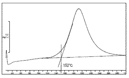
反応開始温度の測定方法
本発明における反応開始温度とは示差走査熱量測定(通称DSC)における発熱カーブのオンセット温度として測定される。
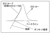
ここでオンセット(反応開始温度)温度は以下のように定義される。試験に用いる上記液状樹脂組成物(アンダーフィル剤)を10mg程度アルミ製のパンに採取し、示差走査熱量測定器(METLER社製 DSC821)にて10℃/分で昇温しDSCカーブを得る。得られたDSCの発熱カーブを図1に示すように、1階微分のピークとなる点での接線と直線で定義されたベースラインの交点をオンセット温度と定義した。
Method for Measuring Reaction Start Temperature The reaction start temperature in the present invention is measured as an onset temperature of an exothermic curve in differential scanning calorimetry (commonly called DSC).
Here, the onset (reaction start temperature) temperature is defined as follows. About 10 mg of the liquid resin composition (underfill agent) used in the test is collected in an aluminum pan and heated at 10 ° C./min with a differential scanning calorimeter (DSC821 manufactured by METLER) to obtain a DSC curve. As shown in FIG. 1, the DSC exothermic curve was defined as the onset temperature at the intersection of the tangent line and the baseline defined by a straight line at the point where the peak of the first-order derivative was obtained.
フラックス残渣は100℃以上の高温、即ちアンダーフィル材の注入温度や硬化させる場合の温度領域においてアンダーフィル材の粘度と同程度まで粘度が低下し、その際エポキシと反応し固形物層を形成する。その層の中に充填剤が進入することは難しく充填剤のほとんど無い層となる。エポキシ樹脂組成物の反応開始温度が低い場合、即ち反応が早い場合、エポキシとフラックスの反応も早く開始し、浮遊層を防止できる。またフラックスとエポキシの反応物はフラックス活性を持たないため、はんだ表面の酸化物層を還元することが抑制されるため放出される水が低減でき、結果としてボイドの低減が可能となる。 The flux residue has a viscosity lower than the viscosity of the underfill material at a high temperature of 100 ° C. or higher, that is, the temperature at which the underfill material is injected or cured, and forms a solid layer by reacting with the epoxy. . It is difficult for the filler to enter the layer, resulting in a layer with almost no filler. When the reaction start temperature of the epoxy resin composition is low, that is, when the reaction is fast, the reaction between the epoxy and the flux starts early, and the floating layer can be prevented. Further, since the reaction product of the flux and the epoxy does not have the flux activity, the reduction of the oxide layer on the solder surface is suppressed, so that the released water can be reduced, and as a result, the void can be reduced.
好ましくは硬化開始温度を160℃以下とすることであるが、155℃以下とすることがさらに好ましい。またアンダーフィル材は前記のように硬化させて素子を封止するが、単にその工程のコストを低減させる目的で硬化促進材を添加させることも可能である。使用可能な硬化促進材としてはカルボン酸類が好適に使用可能であるが、アクリル等でマイクロカプセル化したものが樹脂の可使時間の短縮を防ぐことができるため更に好ましい。 The curing start temperature is preferably 160 ° C. or lower, but more preferably 155 ° C. or lower. In addition, the underfill material is cured as described above to seal the element, but it is also possible to add a curing accelerator for the purpose of simply reducing the cost of the process. Carboxylic acids can be suitably used as usable curing accelerators, but those that are microencapsulated with acrylic or the like are more preferable because they can prevent shortening the pot life of the resin.
本発明の液状エポキシ樹脂組成物は、例えば、液状エポキシ樹脂、芳香族アミン系硬化剤、硬化促進剤、充填剤及びその他の添加剤等を同時に又は別々に、必要により加熱処理を加えながら、撹拌、溶解、混合、分散させることにより得ることができる。これらの混合、撹拌、分散等の装置としては、特に限定されるものではないが、撹拌、加熱装置を備えたライカイ機、3本ロール、ボールミル、プラネタリーミキサー等を用いることができる。またこれら装置を適宜組み合わせて使用してもよい。 The liquid epoxy resin composition of the present invention is stirred, for example, by adding a liquid epoxy resin, an aromatic amine curing agent, a curing accelerator, a filler and other additives at the same time or separately, if necessary with heat treatment. , Dissolved, mixed, and dispersed. The apparatus for mixing, stirring, dispersing and the like is not particularly limited, and a lykai machine, a three roll, a ball mill, a planetary mixer and the like equipped with a stirring and heating device can be used. Moreover, you may use combining these apparatuses suitably.
なお、本発明において、封止材として用いる液状エポキシ樹脂組成物の粘度は、25℃において100Pa・s以下、特に5〜80Pa・sのものが好ましい。 In the present invention, the viscosity of the liquid epoxy resin composition used as the sealing material is preferably 100 Pa · s or less, particularly 5 to 80 Pa · s at 25 ° C.
本発明の液状封止樹脂組成物を用いてフリップチップタイプの半導体素子を封止し、半導体装置を製作する方法は公知の方法を用いることができる。 A known method can be used as a method of sealing a flip chip type semiconductor element using the liquid sealing resin composition of the present invention and manufacturing a semiconductor device.
以下、本発明の実施例および比較例を示して具体的に説明するが、本発明は下記実施例に制限されるものではない。 Examples of the present invention and comparative examples will be described below in detail, but the present invention is not limited to the following examples.
評価は日立超LSI社製のフリップチップ評価キット 半導体素子としてJTEG Phase 2E175 バンプ高さ50μm、ピッチ175μm、15mm×15mm×0.6mmt はんだ組成(Sn−3.0Ag−0.5Cu)を用い基板としてJKIT TYPE VI 電極数5,184ピンを用い、フラックスにTSF−6502(Kester社製)もしくはGelflux 2000BT(Cobar社製)をあらかじめ基板及び素子の突起電極部に塗布したものをフリップチップボンダーで位置決めし、更にIRリフロー炉を用いはんだ接続を行った。また参考としてフラックスを用いずフリップチップボンダーで位置決めする際、260℃に加熱し接続をおこなったパッケージでも評価を行った。 Evaluation is a flip chip evaluation kit manufactured by Hitachi Ultra LSI Co., Ltd. JTEG Phase 2E175 Bump height 50 μm, Pitch 175 μm, 15 mm × 15 mm × 0.6 mmt Solder composition (Sn-3.0Ag-0.5Cu) as a substrate JKIT TYPE VI The number of electrodes is 5,184, and TSF-6502 (manufactured by Kester) or Gelflux 2000BT (manufactured by Cobar) is applied to the substrate and the protruding electrode part of the element as a flux and positioned with a flip chip bonder. Further, solder connection was performed using an IR reflow furnace. Also, as a reference, when positioning with a flip chip bonder without using a flux, evaluation was also performed on a package that was heated to 260 ° C. and connected.
[実施例1〜3、比較例1〜3] [Examples 1-3, Comparative Examples 1-3]
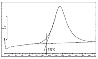
上表1で示す成分を3本ロールで均一に混練することにより、6種の樹脂組成物を得た。ここで反応開始温度は上表により得られた樹脂組成物を10mgアルミパンにとり示差走査熱量測定器(METLER社製 DSC821)を用い10℃/分の昇温速度の条件にて測定した。測定したDSCチャートを図2に示す。 Six types of resin compositions were obtained by uniformly kneading the components shown in Table 1 above with three rolls. Here, the reaction start temperature was measured using a differential scanning calorimeter (DSC821 manufactured by METTLER) at a temperature rising rate of 10 ° C./min. The measured DSC chart is shown in FIG.
これらの樹脂組成物を用いて、以下に示す試験を行った。
ここで用いた材料は以下のものである。
(A)液状エポキシ樹脂
エポキシ樹脂A:ビスフェノールF型エポキシ樹脂(日本化薬(株)製、RE303S−L)
エポキシ樹脂B:下記式(3)で示される3官能型エポキシ樹脂(ジャパンエポキシレジン(株)製、エピコート630H)
The test shown below was done using these resin compositions.
The materials used here are as follows.
(A) Liquid epoxy resin epoxy resin A: bisphenol F type epoxy resin (manufactured by Nippon Kayaku Co., Ltd., RE303S-L)
Epoxy resin B: Trifunctional epoxy resin represented by the following formula (3) (Japan Epoxy Resin Co., Ltd., Epicoat 630H)
共重合体:下記式(5)の化合物と下記式(6)の化合物との付加反応生成物 Copolymer: addition reaction product of a compound of the following formula (5) and a compound of the following formula (6)
(B)硬化剤
硬化剤A:ジエチルジアミノジフェニルメタン(カヤハードA−A 日本化薬社製、)
硬化剤B:ジエチルトルエンジアミン(分子量;178)
(B) Curing agent Curing agent A: Diethyldiaminodiphenylmethane (Kayahard AA manufactured by Nippon Kayaku Co., Ltd.)
Curing agent B: diethyltoluenediamine (molecular weight; 178)
(C)無機充填材
球状シリカ:平均粒子径2.0μm、最大粒径15μmの真球状溶融シリカ(株式会社アドマテックス製)
(D)硬化促進剤
硬化促進剤:サリチル酸を20質量%内包したメタクリル酸メチルの重合体
(E)その他の添加剤
シランカップリング剤:γ−グリシドキシプロピルトリメトキシシラン(KBM403 信越化学工業製)
カーボンブラック:デンカブラック(電気化学工業製)
希釈剤:エチレングリコールモノブチルエーテルアセタート
(C) Inorganic filler spherical silica: true spherical fused silica having an average particle size of 2.0 μm and a maximum particle size of 15 μm (manufactured by Admatechs)
(D) Curing accelerator Curing accelerator: Polymer of methyl methacrylate containing 20% by mass of salicylic acid (E) Other additive Silane coupling agent: γ-glycidoxypropyltrimethoxysilane (KBM403, manufactured by Shin-Etsu Chemical Co., Ltd.) )
Carbon black: Denka Black (manufactured by Denki Kagaku Kogyo)
Diluent: ethylene glycol monobutyl ether acetate
前述の半導体パッケージを110℃の熱板上で加熱し、半導体素子の一辺に混練して均一となった上表1の樹脂組成物をディスペンスし充填させ、160℃のオーブンで120分間樹脂を硬化し、半導体装置を得た。 The above-mentioned semiconductor package is heated on a hot plate at 110 ° C., and kneaded on one side of the semiconductor element, and the resin composition shown in Table 1 above is dispensed and filled, and the resin is cured in an oven at 160 ° C. for 120 minutes. As a result, a semiconductor device was obtained.
上で得られた半導体装置を以下の方法で評価を行った。
[ボイド観察]
超音波断面観察装置(SONIX社製 Quantum 350)を用いボイドの発生状況を観察した。
[断面観察]
得られた半導体装置を断面研磨を行いフラックス層の浮きを観察した。
結果を表2に記す。
ここで用いたパッケージはフラックスとして以下のものを用いて接続させたものである。
パッケージA:TSF6502(KESTER社製)
パッケージB:Gelflux 2000BT(COBER社製)
参考としてパッケージC:フラックスを用いずフリップチップボンダーで位置決めする際、260℃に加熱し接続をおこなったパッケージ
The semiconductor device obtained above was evaluated by the following method.
[Void observation]
The occurrence of voids was observed using an ultrasonic cross-sectional observation apparatus (Quantum 350 manufactured by SONIX).
[Section observation]
The obtained semiconductor device was subjected to cross-sectional polishing, and the floating of the flux layer was observed.
The results are shown in Table 2.
The package used here is connected using the following flux.
Package A: TSF6502 (manufactured by KESTER)
Package B: Gelflux 2000BT (COBER)
For reference, package C: a package that is heated and connected to 260 ° C when positioning with a flip chip bonder without using flux
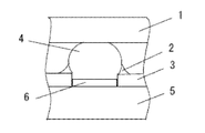
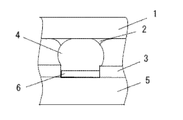
ここにおける断面観察においてフラックスの浮遊層無しの状態の模式図を図1に、浮き有りの模式図を図2にしめすが、参考に行ったパッケージCの断面はフラックスを用いていないためフラックス層自体が見られない。
In the cross-sectional observation here, the schematic diagram of the state without the floating layer of the flux is shown in FIG. 1, and the schematic diagram of the floating state is shown in FIG. Is not seen.
表に示した結果から、明らかなように実施例1〜3はフラックス層の浮きあがりも無く、またボイド性も改善されている。一方比較例はボイドの発生も多く、またフラックス層の浮きが見られる。また参考に行ったフラックスを用いなかったパッケージはボイドの発生がすべてない結果となった。この結果より上記の半導体装置でのボイドは、フラックスの残渣起因と考えられるが、本発明はそれを防止する効果があることが示された。
As is apparent from the results shown in the table, in Examples 1 to 3, there is no floating of the flux layer and the voidability is improved. On the other hand, in the comparative example, there are many voids and the flux layer is lifted. Moreover, the package which did not use the flux performed as a reference resulted in no generation of voids. From this result, it is considered that the void in the semiconductor device is caused by the residue of the flux, but the present invention has the effect of preventing it.
1 半導体素子
2 フラックス層
3 ソルダーレジスト
4 突起電極(ハンダ)
5 基板
6 基板電極
DESCRIPTION OF
5
Claims (4)
Priority Applications (1)
| Application Number | Priority Date | Filing Date | Title |
|---|---|---|---|
| JP2008319207A JP2010143949A (en) | 2008-12-16 | 2008-12-16 | Underfill material and semiconductor device using the same |
Applications Claiming Priority (1)
| Application Number | Priority Date | Filing Date | Title |
|---|---|---|---|
| JP2008319207A JP2010143949A (en) | 2008-12-16 | 2008-12-16 | Underfill material and semiconductor device using the same |
Publications (1)
| Publication Number | Publication Date |
|---|---|
| JP2010143949A true JP2010143949A (en) | 2010-07-01 |
Family
ID=42564702
Family Applications (1)
| Application Number | Title | Priority Date | Filing Date |
|---|---|---|---|
| JP2008319207A Pending JP2010143949A (en) | 2008-12-16 | 2008-12-16 | Underfill material and semiconductor device using the same |
Country Status (1)
| Country | Link |
|---|---|
| JP (1) | JP2010143949A (en) |
Cited By (1)
| Publication number | Priority date | Publication date | Assignee | Title |
|---|---|---|---|---|
| JP2012162585A (en) * | 2011-02-03 | 2012-08-30 | Namics Corp | Resin sealng material for semiconductor |
Citations (10)
| Publication number | Priority date | Publication date | Assignee | Title |
|---|---|---|---|---|
| JPH10231351A (en) * | 1997-02-18 | 1998-09-02 | Sumitomo Bakelite Co Ltd | Liquid injection sealing underfilling material |
| JP2004256646A (en) * | 2003-02-25 | 2004-09-16 | Matsushita Electric Works Ltd | Resin composition for underfill and semiconductor device |
| JP2006219601A (en) * | 2005-02-10 | 2006-08-24 | Hitachi Chem Co Ltd | Liquid epoxy resin composition for sealing |
| JP2006233127A (en) * | 2005-02-28 | 2006-09-07 | Sumitomo Bakelite Co Ltd | Liquid resin composition for sealing used for underfill and semiconductor device using the same and manufacturing method for the same |
| JP2006307189A (en) * | 2005-03-31 | 2006-11-09 | Sumitomo Bakelite Co Ltd | Liquid epoxy resin composition and semiconductor device using the same |
| JP2007231146A (en) * | 2006-03-01 | 2007-09-13 | Shin Etsu Chem Co Ltd | Liquid epoxy resin composition and semiconductor device |
| JP2008106181A (en) * | 2006-10-26 | 2008-05-08 | Matsushita Electric Works Ltd | Epoxy resin composition and semiconductor device |
| JP2008214548A (en) * | 2007-03-06 | 2008-09-18 | Sumitomo Bakelite Co Ltd | Liquid epoxy resin composition and semiconductor device using it |
| JP2009256583A (en) * | 2007-09-28 | 2009-11-05 | Sumitomo Bakelite Co Ltd | Liquid epoxy resin composition and semiconductor device using the same |
| JP2010189664A (en) * | 1999-04-13 | 2010-09-02 | Hitachi Chem Co Ltd | Epoxy resin composition for encapsulation and electronic part device |
-
2008
- 2008-12-16 JP JP2008319207A patent/JP2010143949A/en active Pending
Patent Citations (10)
| Publication number | Priority date | Publication date | Assignee | Title |
|---|---|---|---|---|
| JPH10231351A (en) * | 1997-02-18 | 1998-09-02 | Sumitomo Bakelite Co Ltd | Liquid injection sealing underfilling material |
| JP2010189664A (en) * | 1999-04-13 | 2010-09-02 | Hitachi Chem Co Ltd | Epoxy resin composition for encapsulation and electronic part device |
| JP2004256646A (en) * | 2003-02-25 | 2004-09-16 | Matsushita Electric Works Ltd | Resin composition for underfill and semiconductor device |
| JP2006219601A (en) * | 2005-02-10 | 2006-08-24 | Hitachi Chem Co Ltd | Liquid epoxy resin composition for sealing |
| JP2006233127A (en) * | 2005-02-28 | 2006-09-07 | Sumitomo Bakelite Co Ltd | Liquid resin composition for sealing used for underfill and semiconductor device using the same and manufacturing method for the same |
| JP2006307189A (en) * | 2005-03-31 | 2006-11-09 | Sumitomo Bakelite Co Ltd | Liquid epoxy resin composition and semiconductor device using the same |
| JP2007231146A (en) * | 2006-03-01 | 2007-09-13 | Shin Etsu Chem Co Ltd | Liquid epoxy resin composition and semiconductor device |
| JP2008106181A (en) * | 2006-10-26 | 2008-05-08 | Matsushita Electric Works Ltd | Epoxy resin composition and semiconductor device |
| JP2008214548A (en) * | 2007-03-06 | 2008-09-18 | Sumitomo Bakelite Co Ltd | Liquid epoxy resin composition and semiconductor device using it |
| JP2009256583A (en) * | 2007-09-28 | 2009-11-05 | Sumitomo Bakelite Co Ltd | Liquid epoxy resin composition and semiconductor device using the same |
Cited By (1)
| Publication number | Priority date | Publication date | Assignee | Title |
|---|---|---|---|---|
| JP2012162585A (en) * | 2011-02-03 | 2012-08-30 | Namics Corp | Resin sealng material for semiconductor |
Similar Documents
| Publication | Publication Date | Title |
|---|---|---|
| JP5228426B2 (en) | Liquid resin composition for electronic component sealing and electronic component device using the same | |
| CN102675599B (en) | Method for manufacturing semiconductor device | |
| JP5116152B2 (en) | Resin composition for manufacturing semiconductor devices | |
| JP2007308678A (en) | Liquid epoxy resin composition | |
| US20130197129A1 (en) | Liquid epoxy resin composition and semiconductor device | |
| JP2009024099A (en) | Liquid epoxy resin composition and semiconductor device | |
| JP7167912B2 (en) | Liquid encapsulating resin composition, electronic component device, and method for manufacturing electronic component device | |
| JP2002097257A (en) | Liquid epoxy resin composition and semiconductor device | |
| JP3912515B2 (en) | Liquid epoxy resin composition and semiconductor device | |
| JP3716237B2 (en) | Sealant resin composition | |
| JP6816426B2 (en) | Underfill material and electronic component equipment using it | |
| JP3773022B2 (en) | Flip chip type semiconductor device | |
| JP2007182562A (en) | Liquid resin composition for electronic element and electronic element device | |
| JP2009173744A (en) | Underfill agent composition | |
| JP5317695B2 (en) | COF mounting sealant and semiconductor component sealed using the same | |
| JP2010077234A (en) | Liquid epoxy resin composition and semiconductor device | |
| JP5275297B2 (en) | Liquid epoxy resin composition and semiconductor device sealed with cured product obtained by curing liquid epoxy resin composition | |
| JP2007182561A (en) | Liquid resin composition for electronic components, and electronic component device using the same | |
| JP5013536B2 (en) | Underfill agent composition | |
| JP2010111747A (en) | Underfill agent composition | |
| JP4221585B2 (en) | Liquid epoxy resin composition and semiconductor device | |
| CN1970623B (en) | Liquid epoxy resin composition | |
| JP2012082281A (en) | Liquid epoxy resin composition and semiconductor device | |
| JP4737364B2 (en) | Liquid epoxy resin composition and semiconductor device | |
| JP4622221B2 (en) | Epoxy resin composition and semiconductor device |
Legal Events
| Date | Code | Title | Description |
|---|---|---|---|
| A621 | Written request for application examination |
Free format text: JAPANESE INTERMEDIATE CODE: A621 Effective date: 20101126 |
|
| A977 | Report on retrieval |
Free format text: JAPANESE INTERMEDIATE CODE: A971007 Effective date: 20120425 |
|
| A131 | Notification of reasons for refusal |
Free format text: JAPANESE INTERMEDIATE CODE: A131 Effective date: 20120522 |
|
| RD03 | Notification of appointment of power of attorney |
Free format text: JAPANESE INTERMEDIATE CODE: A7423 Effective date: 20120523 |
|
| A02 | Decision of refusal |
Free format text: JAPANESE INTERMEDIATE CODE: A02 Effective date: 20121003 |