JP2010502005A - 平坦なテーブル表面を整列させるための方法および装置 - Google Patents
平坦なテーブル表面を整列させるための方法および装置 Download PDFInfo
- Publication number
- JP2010502005A JP2010502005A JP2009524919A JP2009524919A JP2010502005A JP 2010502005 A JP2010502005 A JP 2010502005A JP 2009524919 A JP2009524919 A JP 2009524919A JP 2009524919 A JP2009524919 A JP 2009524919A JP 2010502005 A JP2010502005 A JP 2010502005A
- Authority
- JP
- Japan
- Prior art keywords
- position sensor
- table surface
- height
- reference line
- line
- Prior art date
- Legal status (The legal status is an assumption and is not a legal conclusion. Google has not performed a legal analysis and makes no representation as to the accuracy of the status listed.)
- Pending
Links
- 238000000034 method Methods 0.000 title claims description 46
- 238000005259 measurement Methods 0.000 claims abstract description 35
- 238000012937 correction Methods 0.000 claims description 7
- 230000015654 memory Effects 0.000 claims description 7
- 238000004590 computer program Methods 0.000 claims description 2
- 230000006872 improvement Effects 0.000 description 14
- 239000011521 glass Substances 0.000 description 10
- 238000004519 manufacturing process Methods 0.000 description 9
- 230000006870 function Effects 0.000 description 4
- 239000000758 substrate Substances 0.000 description 4
- 238000013461 design Methods 0.000 description 3
- 238000010586 diagram Methods 0.000 description 3
- XUIMIQQOPSSXEZ-UHFFFAOYSA-N Silicon Chemical compound [Si] XUIMIQQOPSSXEZ-UHFFFAOYSA-N 0.000 description 2
- 230000004888 barrier function Effects 0.000 description 2
- 230000008901 benefit Effects 0.000 description 2
- 238000002425 crystallisation Methods 0.000 description 2
- 230000008025 crystallization Effects 0.000 description 2
- 238000003384 imaging method Methods 0.000 description 2
- 238000009434 installation Methods 0.000 description 2
- 230000003287 optical effect Effects 0.000 description 2
- 229910052710 silicon Inorganic materials 0.000 description 2
- 239000010703 silicon Substances 0.000 description 2
- 229910021417 amorphous silicon Inorganic materials 0.000 description 1
- 238000013459 approach Methods 0.000 description 1
- 230000015572 biosynthetic process Effects 0.000 description 1
- 238000004422 calculation algorithm Methods 0.000 description 1
- 238000004364 calculation method Methods 0.000 description 1
- 230000008859 change Effects 0.000 description 1
- 238000011161 development Methods 0.000 description 1
- 238000006073 displacement reaction Methods 0.000 description 1
- 238000011156 evaluation Methods 0.000 description 1
- 239000004973 liquid crystal related substance Substances 0.000 description 1
- 239000011159 matrix material Substances 0.000 description 1
- 238000002844 melting Methods 0.000 description 1
- 230000008018 melting Effects 0.000 description 1
- 229910021420 polycrystalline silicon Inorganic materials 0.000 description 1
- 230000008569 process Effects 0.000 description 1
- 238000012545 processing Methods 0.000 description 1
- 230000003068 static effect Effects 0.000 description 1
- 238000005303 weighing Methods 0.000 description 1
Images




Classifications
-
- G—PHYSICS
- G01—MEASURING; TESTING
- G01B—MEASURING LENGTH, THICKNESS OR SIMILAR LINEAR DIMENSIONS; MEASURING ANGLES; MEASURING AREAS; MEASURING IRREGULARITIES OF SURFACES OR CONTOURS
- G01B11/00—Measuring arrangements characterised by the use of optical techniques
- G01B11/26—Measuring arrangements characterised by the use of optical techniques for measuring angles or tapers; for testing the alignment of axes
- G01B11/27—Measuring arrangements characterised by the use of optical techniques for measuring angles or tapers; for testing the alignment of axes for testing the alignment of axes
- G01B11/272—Measuring arrangements characterised by the use of optical techniques for measuring angles or tapers; for testing the alignment of axes for testing the alignment of axes using photoelectric detection means
-
- G—PHYSICS
- G01—MEASURING; TESTING
- G01B—MEASURING LENGTH, THICKNESS OR SIMILAR LINEAR DIMENSIONS; MEASURING ANGLES; MEASURING AREAS; MEASURING IRREGULARITIES OF SURFACES OR CONTOURS
- G01B11/00—Measuring arrangements characterised by the use of optical techniques
- G01B11/02—Measuring arrangements characterised by the use of optical techniques for measuring length, width or thickness
- G01B11/06—Measuring arrangements characterised by the use of optical techniques for measuring length, width or thickness for measuring thickness ; e.g. of sheet material
- G01B11/0608—Height gauges
-
- G—PHYSICS
- G01—MEASURING; TESTING
- G01D—MEASURING NOT SPECIALLY ADAPTED FOR A SPECIFIC VARIABLE; ARRANGEMENTS FOR MEASURING TWO OR MORE VARIABLES NOT COVERED IN A SINGLE OTHER SUBCLASS; TARIFF METERING APPARATUS; MEASURING OR TESTING NOT OTHERWISE PROVIDED FOR
- G01D11/00—Component parts of measuring arrangements not specially adapted for a specific variable
- G01D11/30—Supports specially adapted for an instrument; Supports specially adapted for a set of instruments
-
- G—PHYSICS
- G01—MEASURING; TESTING
- G01N—INVESTIGATING OR ANALYSING MATERIALS BY DETERMINING THEIR CHEMICAL OR PHYSICAL PROPERTIES
- G01N21/00—Investigating or analysing materials by the use of optical means, i.e. using sub-millimetre waves, infrared, visible or ultraviolet light
- G01N21/01—Arrangements or apparatus for facilitating the optical investigation
- G01N2021/0181—Memory or computer-assisted visual determination
Landscapes
- Physics & Mathematics (AREA)
- General Physics & Mathematics (AREA)
- Length Measuring Devices By Optical Means (AREA)
Abstract
Description
前記テーブル表面に接続された第1の位置センサを用意するステップ、
前記テーブル表面から垂直に離間して配置された少なくとも1つの第2の位置センサを用意するステップ、
前記第1の位置センサを使用することによって、前記基準線に対する少なくとも1つの第1のテーブル高さを割り出すステップ、
前記第1の位置センサを前記少なくとも1つの第2の位置センサに垂直に位置させ、該第2の位置センサを使用することによって前記第1の位置センサに対する基準高さを割り出すステップ、
前記テーブル表面を第1の移動方向に沿って動かし、前記第2の位置センサを使用することによって前記基準高さに対する複数の第2のテーブル高さを割り出すステップ、
前記第2のテーブル高さによって測定平面を決定するステップ、および
前記テーブル表面を前記測定平面に平行に整列させるステップ
を含んでいる方法によって達成される。
Claims (13)
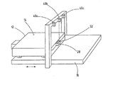
- 基準線(46)に対して横方向に延びる第1の移動方向(20)に沿って平坦なテーブル表面(14)を基準線(46)から所定の間隔をおいて移動させるために、該テーブル表面(14)を前記基準線(46)に対して整列させるための方法であって、
前記テーブル表面(14)に接続された第1の位置センサ(28)を用意するステップ、
前記テーブル表面(14)から垂直に離間して配置された少なくとも1つの第2の位置センサ(40)を用意するステップ、
前記第1の位置センサ(28)を使用することによって、前記基準線(46)に対する少なくとも1つの第1のテーブル高さを割り出すステップ(82)、
前記第1の位置センサ(28)を前記少なくとも1つの第2の位置センサ(40)に垂直に位置させ、前記第2の位置センサ(40)を使用することによって前記第1の位置センサ(28)に対する基準高さを割り出すステップ(92)、
前記テーブル表面(14)を第1の移動方向(20)に沿って動かし、前記第2の位置センサ(40)を使用することによって前記基準高さに対する複数の第2のテーブル高さを割り出すステップ(94)、
前記第2のテーブル高さによって測定平面(72)を決定するステップ、および
前記テーブル表面(14)を前記測定平面(72)に平行に整列させるステップ
を含んでいる方法。 - 少なくとも2つの前記第2の位置センサ(40a、40b、40c)が用意され、これらの位置センサが、前記第1の移動方向(20)に対する横方向に互いにずらされて配置され、前記第2のテーブル高さが、前記少なくとも2つの第2の位置センサ(40a、40b、40c)を使用することによって割り出され、前記測定平面(72)が決定されることを特徴とする請求項1に記載の方法。
- 前記テーブル表面(14)が、前記測定平面を決定するために、前記第1の移動方向(20)に対して横方向に動かされることを特徴とする請求項1に記載の方法。
- 前記基準線(46)が、前記テーブル表面(14)を横切って走るレーザ線であり、前記第1の位置センサ(28)が、前記レーザ線を検出するように設計されていることを特徴とする請求項1〜3のいずれか1項に記載の方法。
- 前記レーザ線(46)が、扇状に広げられて前記テーブル表面(14)に垂直に突き当たるレーザビーム(42)の焦線であることを特徴とする請求項4に記載の方法。
- 前記第1の位置センサ(28)が、前記レーザ線(46)を取得するためのカメラ(30)を含んでいることを特徴とする請求項4または5に記載の方法。
- 前記第1の位置センサ(28)が、少なくとも1つの基準面(32)を有しており、該基準面(32)が、前記基準高さを割り出すために前記少なくとも1つの第2の位置センサ(40)によって取得されることを特徴とする請求項1〜6のいずれか1項に記載の方法。
- 前記第1の位置センサ(28)が、第2の移動方向(34)に沿ってテーブル表面(14)に対して動かされ、前記基準線(46)に対する複数の前記第1のテーブル高さが記録され、前記第2の移動方向(34)と前記基準線(46)との間の傾き(68)の角度を表す補正値が決定されることを特徴とする請求項1〜7のいずれか1項に記載の方法。
- 前記第1のテーブル高さが、前記基準線(46)が前記第1の位置センサ(28)によって検出されるまで、前記テーブル表面(14)を垂線方向(24)に動かすことによって割り出されることを特徴とする請求項1〜8のいずれか1項に記載の方法。
- 前記テーブル表面(14)が、メモリ(62)に恒久的に保存された制御値(56、58)によって整列させられることを特徴とする請求項1〜9のいずれか1項に記載の方法。
- 前記テーブル表面(14)が、該テーブル表面に垂直な垂直軸(50)を中心にして回転させられ、前記測定平面(72)の決定および前記テーブル表面(14)の整列が、回転後に繰り返されることを特徴とする請求項1〜10のいずれか1項に記載の方法。
- コンピュータ上で実行されたときに請求項1〜11のいずれか1項に記載の方法を実行するように設計されているプログラムコードを含んでいるコンピュータプログラム製品。
- 基準線(46)に対して横方向に延びる第1の移動方向(20)に沿って平坦なテーブル表面(14)を前記基準線(46)から所定の間隔をおいて移動させるために、前記テーブル表面(14)を前記基準線(46)に対して整列させるための装置であって、
前記テーブル表面(14)に接続された第1の位置センサ(28)、
テーブル表面(14)から垂直に離間して配置された少なくとも1つの第2の位置センサ(40)、
前記第1の位置センサ(28)を使用することによって、前記基準線(46)に対する少なくとも1つの第1のテーブル高さを割り出すための第1の測定装置(26、60、82)、
前記第1の位置センサ(28)に対する前記第2の位置センサ(40)の基準高さを割り出すための第2の測定装置(40、60、92)、
前記第2の位置センサ(40)を使用することによって、前記基準高さに対する複数の第2のテーブル高さを割り出すための第3の測定装置(40、60、94)、
前記第2のテーブル高さによって測定平面(72)を決定するための演算ユニット(54)、および
前記テーブル表面(14)を第1の移動方向(20)に沿って動かすため、および前記テーブル表面(14)を前記測定平面(72)に平行に整列させるための駆動装置(18、22)
を備えている装置。
Applications Claiming Priority (2)
| Application Number | Priority Date | Filing Date | Title |
|---|---|---|---|
| DE102006041657A DE102006041657A1 (de) | 2006-08-24 | 2006-08-24 | Verfahren und Vorrichtung zum Ausrichten einer ebenen Tischoberfläche |
| PCT/EP2007/006791 WO2008022693A1 (de) | 2006-08-24 | 2007-08-01 | Verfahren und vorrichtung zum ausrichten einer ebenen tischoberfläche |
Publications (1)
| Publication Number | Publication Date |
|---|---|
| JP2010502005A true JP2010502005A (ja) | 2010-01-21 |
Family
ID=38658503
Family Applications (1)
| Application Number | Title | Priority Date | Filing Date |
|---|---|---|---|
| JP2009524919A Pending JP2010502005A (ja) | 2006-08-24 | 2007-08-01 | 平坦なテーブル表面を整列させるための方法および装置 |
Country Status (4)
| Country | Link |
|---|---|
| JP (1) | JP2010502005A (ja) |
| KR (1) | KR20090052329A (ja) |
| DE (1) | DE102006041657A1 (ja) |
| WO (1) | WO2008022693A1 (ja) |
Cited By (1)
| Publication number | Priority date | Publication date | Assignee | Title |
|---|---|---|---|---|
| KR101914101B1 (ko) * | 2011-06-28 | 2018-11-02 | 삼성전자 주식회사 | 척의 제어 장치 및 방법, 노광 장치 및 그 제어 방법 |
Families Citing this family (1)
| Publication number | Priority date | Publication date | Assignee | Title |
|---|---|---|---|---|
| KR101428405B1 (ko) | 2013-08-07 | 2014-08-07 | 현대자동차주식회사 | 차량용 휠얼라이먼트 측정장치, 그를 이용한 측정시스템 및 측정방법 |
Citations (4)
| Publication number | Priority date | Publication date | Assignee | Title |
|---|---|---|---|---|
| JPH07201699A (ja) * | 1993-12-28 | 1995-08-04 | Nikon Corp | ステージ装置 |
| JPH10270360A (ja) * | 1997-03-26 | 1998-10-09 | Seiko Epson Corp | 結晶性半導体膜の製造方法、およびアニール装置および薄膜トランジスタの製造方法および液晶表示装置用アクティブマトリクス基板 |
| JP2000349043A (ja) * | 1999-06-08 | 2000-12-15 | Sumitomo Heavy Ind Ltd | 矩形ビーム用精密焦点合せ方法 |
| JP2008546187A (ja) * | 2005-05-26 | 2008-12-18 | サイマー インコーポレイテッド | ラインビームとして成形されたレーザと基板上に堆積された膜との間の相互作用を実現するためのシステム及び方法 |
Family Cites Families (2)
| Publication number | Priority date | Publication date | Assignee | Title |
|---|---|---|---|---|
| JP2728042B2 (ja) * | 1995-08-22 | 1998-03-18 | 日本電気株式会社 | 基板アライメント装置 |
| US7221463B2 (en) * | 2003-03-14 | 2007-05-22 | Canon Kabushiki Kaisha | Positioning apparatus, exposure apparatus, and method for producing device |
-
2006
- 2006-08-24 DE DE102006041657A patent/DE102006041657A1/de not_active Withdrawn
-
2007
- 2007-08-01 KR KR1020097003667A patent/KR20090052329A/ko not_active Ceased
- 2007-08-01 WO PCT/EP2007/006791 patent/WO2008022693A1/de not_active Ceased
- 2007-08-01 JP JP2009524919A patent/JP2010502005A/ja active Pending
Patent Citations (4)
| Publication number | Priority date | Publication date | Assignee | Title |
|---|---|---|---|---|
| JPH07201699A (ja) * | 1993-12-28 | 1995-08-04 | Nikon Corp | ステージ装置 |
| JPH10270360A (ja) * | 1997-03-26 | 1998-10-09 | Seiko Epson Corp | 結晶性半導体膜の製造方法、およびアニール装置および薄膜トランジスタの製造方法および液晶表示装置用アクティブマトリクス基板 |
| JP2000349043A (ja) * | 1999-06-08 | 2000-12-15 | Sumitomo Heavy Ind Ltd | 矩形ビーム用精密焦点合せ方法 |
| JP2008546187A (ja) * | 2005-05-26 | 2008-12-18 | サイマー インコーポレイテッド | ラインビームとして成形されたレーザと基板上に堆積された膜との間の相互作用を実現するためのシステム及び方法 |
Cited By (1)
| Publication number | Priority date | Publication date | Assignee | Title |
|---|---|---|---|---|
| KR101914101B1 (ko) * | 2011-06-28 | 2018-11-02 | 삼성전자 주식회사 | 척의 제어 장치 및 방법, 노광 장치 및 그 제어 방법 |
Also Published As
| Publication number | Publication date |
|---|---|
| KR20090052329A (ko) | 2009-05-25 |
| WO2008022693A1 (de) | 2008-02-28 |
| DE102006041657A1 (de) | 2008-03-13 |
Similar Documents
| Publication | Publication Date | Title |
|---|---|---|
| JP3511450B2 (ja) | 光学式測定装置の位置校正方法 | |
| TWI645267B (zh) | 一種光學測量裝置和方法 | |
| TWI433256B (zh) | 定位工具之x-y定位的校準方法及具有這種定位工具的裝置 | |
| CN105423917B (zh) | 位置敏感探测器定位误差的标定方法 | |
| JP5350169B2 (ja) | オフセット量校正方法および表面性状測定機 | |
| JP6794536B2 (ja) | 光学式測定装置及び方法 | |
| JP2009069151A (ja) | 座標測定器の移動要素の空間位置を決定するための手段及び方法 | |
| KR102856484B1 (ko) | 간섭 측정 디바이스 | |
| CN107883866B (zh) | 一种光学测量装置和方法 | |
| US20130161484A1 (en) | Auto-focusing apparatus and method with timing-sequential light spots | |
| US9366975B2 (en) | Stage transferring device and position measuring method thereof | |
| US11709050B2 (en) | Position measurement method using a calibration plate to correct a detection value from the position detector | |
| US8149383B2 (en) | Method for determining the systematic error in the measurement of positions of edges of structures on a substrate resulting from the substrate topology | |
| JP2007305696A (ja) | 位置決め装置の精度測定方法 | |
| JP2009025304A (ja) | 基板上の構造位置の測定値の補正値決定方法 | |
| KR20090052329A (ko) | 평면형 테이블 표면을 정렬하기 위한 방법 및 디바이스 | |
| CN112908898B (zh) | 控片量测方法及量测装置 | |
| JPH0854234A (ja) | 三次元座標位置計測方法 | |
| CN109269441B (zh) | 一种弓形架系统几何性能的误差检测方法 | |
| JP5781397B2 (ja) | 円形状測定方法および装置 | |
| JP2977307B2 (ja) | 試料面高さ測定方法 | |
| CN105807571A (zh) | 一种光刻机用调焦调平系统及其调焦调平方法 | |
| JPH09199573A (ja) | 位置決めステージ装置およびこれを用いた露光装置 | |
| KR102870541B1 (ko) | 한 쌍의 센서를 이용한 웨이퍼 전영역 두께 측정 방법 및 장치 | |
| CN111272095A (zh) | 一种高精度二维位置传感器对心检测装置和方法 |
Legal Events
| Date | Code | Title | Description |
|---|---|---|---|
| A621 | Written request for application examination |
Free format text: JAPANESE INTERMEDIATE CODE: A621 Effective date: 20100602 |
|
| A977 | Report on retrieval |
Free format text: JAPANESE INTERMEDIATE CODE: A971007 Effective date: 20121206 |
|
| A131 | Notification of reasons for refusal |
Free format text: JAPANESE INTERMEDIATE CODE: A131 Effective date: 20130108 |
|
| A601 | Written request for extension of time |
Free format text: JAPANESE INTERMEDIATE CODE: A601 Effective date: 20130327 |
|
| A602 | Written permission of extension of time |
Free format text: JAPANESE INTERMEDIATE CODE: A602 Effective date: 20130403 |
|
| A02 | Decision of refusal |
Free format text: JAPANESE INTERMEDIATE CODE: A02 Effective date: 20131105 |