JP2012184773A - 立軸ポンプ - Google Patents
立軸ポンプ Download PDFInfo
- Publication number
- JP2012184773A JP2012184773A JP2012148671A JP2012148671A JP2012184773A JP 2012184773 A JP2012184773 A JP 2012184773A JP 2012148671 A JP2012148671 A JP 2012148671A JP 2012148671 A JP2012148671 A JP 2012148671A JP 2012184773 A JP2012184773 A JP 2012184773A
- Authority
- JP
- Japan
- Prior art keywords
- pump
- impeller
- vertical shaft
- load receiving
- divided bodies
- Prior art date
- Legal status (The legal status is an assumption and is not a legal conclusion. Google has not performed a legal analysis and makes no representation as to the accuracy of the status listed.)
- Pending
Links
- 230000002093 peripheral effect Effects 0.000 claims description 9
- 238000012423 maintenance Methods 0.000 abstract description 6
- 238000005086 pumping Methods 0.000 abstract description 2
- 239000000725 suspension Substances 0.000 description 21
- XLYOFNOQVPJJNP-UHFFFAOYSA-N water Substances O XLYOFNOQVPJJNP-UHFFFAOYSA-N 0.000 description 17
- 238000009434 installation Methods 0.000 description 13
- 238000007689 inspection Methods 0.000 description 8
- 238000000034 method Methods 0.000 description 5
- 239000003638 chemical reducing agent Substances 0.000 description 3
- 230000007797 corrosion Effects 0.000 description 3
- 238000005260 corrosion Methods 0.000 description 3
- 230000001771 impaired effect Effects 0.000 description 3
- 239000007788 liquid Substances 0.000 description 3
- 238000010586 diagram Methods 0.000 description 2
- 238000003780 insertion Methods 0.000 description 2
- 230000037431 insertion Effects 0.000 description 2
- 238000012986 modification Methods 0.000 description 2
- 230000004048 modification Effects 0.000 description 2
- NJPPVKZQTLUDBO-UHFFFAOYSA-N novaluron Chemical compound C1=C(Cl)C(OC(F)(F)C(OC(F)(F)F)F)=CC=C1NC(=O)NC(=O)C1=C(F)C=CC=C1F NJPPVKZQTLUDBO-UHFFFAOYSA-N 0.000 description 2
- 230000002159 abnormal effect Effects 0.000 description 1
- 238000010276 construction Methods 0.000 description 1
- 230000008878 coupling Effects 0.000 description 1
- 238000010168 coupling process Methods 0.000 description 1
- 238000005859 coupling reaction Methods 0.000 description 1
- 238000000354 decomposition reaction Methods 0.000 description 1
- -1 electric motor Substances 0.000 description 1
- 230000008595 infiltration Effects 0.000 description 1
- 238000001764 infiltration Methods 0.000 description 1
- 230000002035 prolonged effect Effects 0.000 description 1
- 230000002787 reinforcement Effects 0.000 description 1
- 239000002002 slurry Substances 0.000 description 1
- 238000009423 ventilation Methods 0.000 description 1
Images




Landscapes
- Structures Of Non-Positive Displacement Pumps (AREA)
Abstract
【解決手段】本発明の立軸ポンプは、回転軸6と、回転軸6に連結された羽根車10と、羽根車10の回転を支持する水中軸受12と、回転軸6および羽根車10を収容するポンプケーシング2とを備える。ポンプケーシング2は、複数の分割体1a,1b,3から構成され、これら分割体1a,1b,3には、それぞれ、少なくとも1つの分割体の荷重を支持することができる荷重受け部25A,25B,25Cが設けられている。
【選択図】図3
Description
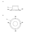
本発明の好ましい態様は、前記荷重受け部は、前記複数の分割体の外周面にそれぞれ固定されていることを特徴とする。
本発明の好ましい態様は、前記荷重受け部は、前記複数の分割体に着脱可能に取り付けられることを特徴とする。
本参考例の好ましい態様は、前記水中軸受は、上端が密閉された空間内に配置されていることを特徴とする。
本参考例の好ましい態様は、前記ポンプケーシングは、複数の分割体から構成され、前記分割体には、前記分割体の荷重を支持する荷重受け部が設けられていることを特徴とする。
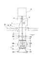
図2は本発明の第1の実施形態に係る立軸ポンプの全体構成を示す断面図である。
図2に示すように、立軸ポンプは、吸込ベルマウス1a及びポンプボウル1bを有するインペラケーシング1と、インペラケーシング1を水槽内に吊り下げる吊下管3と、吊下管3の上端に接続される吐出曲管4と、インペラケーシング1内に収容される羽根車10と、羽根車10が固定される回転軸(立軸)6とを備えている。吊下管3は、水槽上部のポンプ据付床22に形成された挿通孔24を通して下方に延び、吊下管3の上端に設けられた据付用ベース23を介してポンプ据付床22に固定される。回転軸6は、吐出曲管4、吊下管3、及びインペラケーシング1内を通って鉛直方向に延びている。なお、インペラケーシング1及び吊下管3によりポンプケーシング2が構成される。
L×F=f2×(L−H) ・・・(1)
すなわち、
f2=L×F/(L−H) ・・・(2)
L×F=f2´×(L+H´) ・・・(3)
すなわち、
f2´=L×F/(L+H´) ・・・(4)
ここで、H´≒0であるから、式(4)から次の式が導かれる。
f2´=F ・・・(5)
上記式(2)および式(5)から以下の式が導かれる。
f2´/f2=(L−H)/L<1 ・・・(6)
よって、f2´<f2となる。このことから、水中軸受12に作用する力は、第1の実施形態に係る支持構造第よりも、第2の実施形態に係る支持構造の方が小さくなることがわかる。その結果、水中軸受12の摩耗の度合いおよび取替頻度を低くすることができる。
1a 吸込ベルマウス
1b ポンプボウル
2 ポンプケーシング
3 吊下管
4 吐出曲管
6 回転軸
7,17 支持部材
10 羽根車
10a インペラハブ
10b インペラ
11 外軸受
12,15 水中軸受
13 ボウルブッシュ
14 ガイドベーン
18 駆動源
19 ハンドホール
22 ポンプ据付床
23 据付用ベース
24 ポンプ挿通孔
25A〜25E 荷重受け部
26 昇降機
27 台座
29 内部空間
30 固定軸
31 支持部材
Claims (4)
- 回転軸と、
前記回転軸に連結された羽根車と、
前記羽根車の回転を支持する水中軸受と、
前記回転軸および前記羽根車を収容するポンプケーシングとを備え、
前記ポンプケーシングは、複数の分割体から構成され、
前記複数の分割体には、それぞれ、前記複数の分割体の少なくとも1つの荷重を支持することができる荷重受け部が設けられていることを特徴とする立軸ポンプ。 - 前記複数の分割体の分解および組み立て時には、前記複数の分割体のうちの下方の分割体は、上方の分割体に設けられた前記荷重受け部に係止された昇降機により前記上方の分割体から吊り下げられることが可能となっていることを特徴とする請求項1に記載の立軸ポンプ。
- 前記荷重受け部は、前記複数の分割体の外周面にそれぞれ固定されていることを特徴とする請求項1または2に記載の立軸ポンプ。
- 前記荷重受け部は、前記複数の分割体に着脱可能に取り付けられることを特徴とする請求項1または2に記載の立軸ポンプ。
Priority Applications (1)
| Application Number | Priority Date | Filing Date | Title |
|---|---|---|---|
| JP2012148671A JP2012184773A (ja) | 2012-07-02 | 2012-07-02 | 立軸ポンプ |
Applications Claiming Priority (1)
| Application Number | Priority Date | Filing Date | Title |
|---|---|---|---|
| JP2012148671A JP2012184773A (ja) | 2012-07-02 | 2012-07-02 | 立軸ポンプ |
Related Parent Applications (1)
| Application Number | Title | Priority Date | Filing Date |
|---|---|---|---|
| JP2007340278A Division JP5155653B2 (ja) | 2007-12-28 | 2007-12-28 | 立軸ポンプ |
Publications (1)
| Publication Number | Publication Date |
|---|---|
| JP2012184773A true JP2012184773A (ja) | 2012-09-27 |
Family
ID=47015039
Family Applications (1)
| Application Number | Title | Priority Date | Filing Date |
|---|---|---|---|
| JP2012148671A Pending JP2012184773A (ja) | 2012-07-02 | 2012-07-02 | 立軸ポンプ |
Country Status (1)
| Country | Link |
|---|---|
| JP (1) | JP2012184773A (ja) |
Cited By (3)
| Publication number | Priority date | Publication date | Assignee | Title |
|---|---|---|---|---|
| CN106574623A (zh) * | 2014-08-22 | 2017-04-19 | 株式会社荏原制作所 | 立轴泵 |
| CN111946655A (zh) * | 2020-08-05 | 2020-11-17 | 江苏新浪泵业科技有限公司 | 一种立式无密封自吸泵 |
| JP7518254B2 (ja) | 2020-02-17 | 2024-07-17 | 株式会社電業社機械製作所 | 立軸ポンプ |
Citations (4)
| Publication number | Priority date | Publication date | Assignee | Title |
|---|---|---|---|---|
| JPS438440Y1 (ja) * | 1965-02-12 | 1968-04-15 | ||
| JPS60188895A (ja) * | 1984-03-09 | 1985-09-26 | 株式会社日立製作所 | 立軸ポンプの保守装置 |
| JPS61283798A (ja) * | 1985-06-07 | 1986-12-13 | Dengiyoushiya Kikai Seisakusho:Kk | プルアウト形立軸ポンプの外筒部品据付方法 |
| JP2004196525A (ja) * | 2002-12-20 | 2004-07-15 | Shin Meiwa Ind Co Ltd | 水中ポンプ吊下げ用チェーンの上端支持装置 |
-
2012
- 2012-07-02 JP JP2012148671A patent/JP2012184773A/ja active Pending
Patent Citations (4)
| Publication number | Priority date | Publication date | Assignee | Title |
|---|---|---|---|---|
| JPS438440Y1 (ja) * | 1965-02-12 | 1968-04-15 | ||
| JPS60188895A (ja) * | 1984-03-09 | 1985-09-26 | 株式会社日立製作所 | 立軸ポンプの保守装置 |
| JPS61283798A (ja) * | 1985-06-07 | 1986-12-13 | Dengiyoushiya Kikai Seisakusho:Kk | プルアウト形立軸ポンプの外筒部品据付方法 |
| JP2004196525A (ja) * | 2002-12-20 | 2004-07-15 | Shin Meiwa Ind Co Ltd | 水中ポンプ吊下げ用チェーンの上端支持装置 |
Cited By (4)
| Publication number | Priority date | Publication date | Assignee | Title |
|---|---|---|---|---|
| CN106574623A (zh) * | 2014-08-22 | 2017-04-19 | 株式会社荏原制作所 | 立轴泵 |
| CN106574623B (zh) * | 2014-08-22 | 2018-12-11 | 株式会社荏原制作所 | 立轴泵 |
| JP7518254B2 (ja) | 2020-02-17 | 2024-07-17 | 株式会社電業社機械製作所 | 立軸ポンプ |
| CN111946655A (zh) * | 2020-08-05 | 2020-11-17 | 江苏新浪泵业科技有限公司 | 一种立式无密封自吸泵 |
Similar Documents
| Publication | Publication Date | Title |
|---|---|---|
| JP2012184773A (ja) | 立軸ポンプ | |
| JP5671334B2 (ja) | 立軸ポンプ | |
| CN100549427C (zh) | 大型潜水电泵的安装方法 | |
| JP7454516B2 (ja) | ロータ吊り具、ロータ支持治具、ロータの吊り上げ方法、及び回転機械の分解方法 | |
| CN1100205C (zh) | 水力机械 | |
| JP5155653B2 (ja) | 立軸ポンプ | |
| JP5344751B2 (ja) | 立軸ポンプ | |
| CN104847598A (zh) | 风力发电机组及变桨驱动部件的更换装置和更换方法 | |
| CN205297940U (zh) | 一种上充泵 | |
| CN106662109B (zh) | 立轴泵 | |
| JP6235833B2 (ja) | ポンプ吊上げ治具、ポンプ吊上げ方法、ポンプ分解方法 | |
| JP6948278B2 (ja) | 点検用の歩廊を備えたポンプシステム | |
| CN109185008A (zh) | 一种大型轴流转浆式四体联吊组装平衡施工方法 | |
| JP2011106331A (ja) | コラム式水中ポンプ | |
| CN215748961U (zh) | 600mw哈汽机组主机轴承箱盖拆装专用组合工具 | |
| BR112020009220A2 (pt) | método para converter uma célula de flotação aspirada naturalmente em uma célula de flotação de gás forçado e aparelho do mesmo | |
| JP7345990B2 (ja) | 立軸ポンプ | |
| CN209507412U (zh) | 一种平衡梁 | |
| JP7129357B2 (ja) | 車室半体の上下反転方法、それに用いる回転シャフトブラケット及び反転用架台 | |
| JP2013096245A (ja) | 水力機械およびその分解方法 | |
| CN221015702U (zh) | 一种磁力搅拌外磁转子防跳动装置 | |
| CN222846313U (zh) | 液压站在抓斗筒体内的安装结构 | |
| JP2004162558A (ja) | 立軸ポンプ | |
| CN220283310U (zh) | 一种蜗壳内件吊装装置 | |
| CN216009036U (zh) | 一种适用于大型机组的找正装置 |
Legal Events
| Date | Code | Title | Description |
|---|---|---|---|
| A621 | Written request for application examination |
Free format text: JAPANESE INTERMEDIATE CODE: A621 Effective date: 20120702 |
|
| A977 | Report on retrieval |
Free format text: JAPANESE INTERMEDIATE CODE: A971007 Effective date: 20130522 |
|
| A131 | Notification of reasons for refusal |
Free format text: JAPANESE INTERMEDIATE CODE: A131 Effective date: 20130528 |
|
| A521 | Written amendment |
Free format text: JAPANESE INTERMEDIATE CODE: A523 Effective date: 20130723 |
|
| A131 | Notification of reasons for refusal |
Free format text: JAPANESE INTERMEDIATE CODE: A131 Effective date: 20130903 |
|
| A02 | Decision of refusal |
Free format text: JAPANESE INTERMEDIATE CODE: A02 Effective date: 20140107 |