JP2012193788A - 制御弁 - Google Patents
制御弁 Download PDFInfo
- Publication number
- JP2012193788A JP2012193788A JP2011057662A JP2011057662A JP2012193788A JP 2012193788 A JP2012193788 A JP 2012193788A JP 2011057662 A JP2011057662 A JP 2011057662A JP 2011057662 A JP2011057662 A JP 2011057662A JP 2012193788 A JP2012193788 A JP 2012193788A
- Authority
- JP
- Japan
- Prior art keywords
- signal pressure
- communication
- spool
- pressure passage
- pilot
- Prior art date
- Legal status (The legal status is an assumption and is not a legal conclusion. Google has not performed a legal analysis and makes no representation as to the accuracy of the status listed.)
- Granted
Links
Images


Classifications
-
- F—MECHANICAL ENGINEERING; LIGHTING; HEATING; WEAPONS; BLASTING
- F16—ENGINEERING ELEMENTS AND UNITS; GENERAL MEASURES FOR PRODUCING AND MAINTAINING EFFECTIVE FUNCTIONING OF MACHINES OR INSTALLATIONS; THERMAL INSULATION IN GENERAL
- F16K—VALVES; TAPS; COCKS; ACTUATING-FLOATS; DEVICES FOR VENTING OR AERATING
- F16K3/00—Gate valves or sliding valves, i.e. cut-off apparatus with closing members having a sliding movement along the seat for opening and closing
- F16K3/22—Gate valves or sliding valves, i.e. cut-off apparatus with closing members having a sliding movement along the seat for opening and closing with sealing faces shaped as surfaces of solids of revolution
- F16K3/24—Gate valves or sliding valves, i.e. cut-off apparatus with closing members having a sliding movement along the seat for opening and closing with sealing faces shaped as surfaces of solids of revolution with cylindrical valve members
- F16K3/26—Gate valves or sliding valves, i.e. cut-off apparatus with closing members having a sliding movement along the seat for opening and closing with sealing faces shaped as surfaces of solids of revolution with cylindrical valve members with fluid passages in the valve member
-
- F—MECHANICAL ENGINEERING; LIGHTING; HEATING; WEAPONS; BLASTING
- F15—FLUID-PRESSURE ACTUATORS; HYDRAULICS OR PNEUMATICS IN GENERAL
- F15B—SYSTEMS ACTING BY MEANS OF FLUIDS IN GENERAL; FLUID-PRESSURE ACTUATORS, e.g. SERVOMOTORS; DETAILS OF FLUID-PRESSURE SYSTEMS, NOT OTHERWISE PROVIDED FOR
- F15B13/00—Details of servomotor systems ; Valves for servomotor systems
- F15B13/02—Fluid distribution or supply devices characterised by their adaptation to the control of servomotors
- F15B13/04—Fluid distribution or supply devices characterised by their adaptation to the control of servomotors for use with a single servomotor
- F15B13/042—Fluid distribution or supply devices characterised by their adaptation to the control of servomotors for use with a single servomotor operated by fluid pressure
- F15B13/043—Fluid distribution or supply devices characterised by their adaptation to the control of servomotors for use with a single servomotor operated by fluid pressure with electrically-controlled pilot valves
-
- F—MECHANICAL ENGINEERING; LIGHTING; HEATING; WEAPONS; BLASTING
- F15—FLUID-PRESSURE ACTUATORS; HYDRAULICS OR PNEUMATICS IN GENERAL
- F15B—SYSTEMS ACTING BY MEANS OF FLUIDS IN GENERAL; FLUID-PRESSURE ACTUATORS, e.g. SERVOMOTORS; DETAILS OF FLUID-PRESSURE SYSTEMS, NOT OTHERWISE PROVIDED FOR
- F15B13/00—Details of servomotor systems ; Valves for servomotor systems
- F15B13/02—Fluid distribution or supply devices characterised by their adaptation to the control of servomotors
- F15B13/04—Fluid distribution or supply devices characterised by their adaptation to the control of servomotors for use with a single servomotor
- F15B13/0401—Valve members; Fluid interconnections therefor
- F15B13/0402—Valve members; Fluid interconnections therefor for linearly sliding valves, e.g. spool valves
-
- F—MECHANICAL ENGINEERING; LIGHTING; HEATING; WEAPONS; BLASTING
- F15—FLUID-PRESSURE ACTUATORS; HYDRAULICS OR PNEUMATICS IN GENERAL
- F15B—SYSTEMS ACTING BY MEANS OF FLUIDS IN GENERAL; FLUID-PRESSURE ACTUATORS, e.g. SERVOMOTORS; DETAILS OF FLUID-PRESSURE SYSTEMS, NOT OTHERWISE PROVIDED FOR
- F15B13/00—Details of servomotor systems ; Valves for servomotor systems
- F15B13/02—Fluid distribution or supply devices characterised by their adaptation to the control of servomotors
- F15B13/04—Fluid distribution or supply devices characterised by their adaptation to the control of servomotors for use with a single servomotor
- F15B13/042—Fluid distribution or supply devices characterised by their adaptation to the control of servomotors for use with a single servomotor operated by fluid pressure
-
- F—MECHANICAL ENGINEERING; LIGHTING; HEATING; WEAPONS; BLASTING
- F16—ENGINEERING ELEMENTS AND UNITS; GENERAL MEASURES FOR PRODUCING AND MAINTAINING EFFECTIVE FUNCTIONING OF MACHINES OR INSTALLATIONS; THERMAL INSULATION IN GENERAL
- F16K—VALVES; TAPS; COCKS; ACTUATING-FLOATS; DEVICES FOR VENTING OR AERATING
- F16K11/00—Multiple-way valves, e.g. mixing valves; Pipe fittings incorporating such valves
- F16K11/02—Multiple-way valves, e.g. mixing valves; Pipe fittings incorporating such valves with all movable sealing faces moving as one unit
- F16K11/06—Multiple-way valves, e.g. mixing valves; Pipe fittings incorporating such valves with all movable sealing faces moving as one unit comprising only sliding valves, i.e. sliding closure elements
- F16K11/065—Multiple-way valves, e.g. mixing valves; Pipe fittings incorporating such valves with all movable sealing faces moving as one unit comprising only sliding valves, i.e. sliding closure elements with linearly sliding closure members
- F16K11/07—Multiple-way valves, e.g. mixing valves; Pipe fittings incorporating such valves with all movable sealing faces moving as one unit comprising only sliding valves, i.e. sliding closure elements with linearly sliding closure members with cylindrical slides
-
- F—MECHANICAL ENGINEERING; LIGHTING; HEATING; WEAPONS; BLASTING
- F16—ENGINEERING ELEMENTS AND UNITS; GENERAL MEASURES FOR PRODUCING AND MAINTAINING EFFECTIVE FUNCTIONING OF MACHINES OR INSTALLATIONS; THERMAL INSULATION IN GENERAL
- F16K—VALVES; TAPS; COCKS; ACTUATING-FLOATS; DEVICES FOR VENTING OR AERATING
- F16K31/00—Actuating devices; Operating means; Releasing devices
- F16K31/12—Actuating devices; Operating means; Releasing devices actuated by fluid
- F16K31/122—Actuating devices; Operating means; Releasing devices actuated by fluid the fluid acting on a piston
- F16K31/124—Actuating devices; Operating means; Releasing devices actuated by fluid the fluid acting on a piston servo actuated
-
- F—MECHANICAL ENGINEERING; LIGHTING; HEATING; WEAPONS; BLASTING
- F15—FLUID-PRESSURE ACTUATORS; HYDRAULICS OR PNEUMATICS IN GENERAL
- F15B—SYSTEMS ACTING BY MEANS OF FLUIDS IN GENERAL; FLUID-PRESSURE ACTUATORS, e.g. SERVOMOTORS; DETAILS OF FLUID-PRESSURE SYSTEMS, NOT OTHERWISE PROVIDED FOR
- F15B2211/00—Circuits for servomotor systems
- F15B2211/70—Output members, e.g. hydraulic motors or cylinders or control therefor
- F15B2211/78—Control of multiple output members
- F15B2211/782—Concurrent control, e.g. synchronisation of two or more actuators
-
- Y—GENERAL TAGGING OF NEW TECHNOLOGICAL DEVELOPMENTS; GENERAL TAGGING OF CROSS-SECTIONAL TECHNOLOGIES SPANNING OVER SEVERAL SECTIONS OF THE IPC; TECHNICAL SUBJECTS COVERED BY FORMER USPC CROSS-REFERENCE ART COLLECTIONS [XRACs] AND DIGESTS
- Y10—TECHNICAL SUBJECTS COVERED BY FORMER USPC
- Y10T—TECHNICAL SUBJECTS COVERED BY FORMER US CLASSIFICATION
- Y10T137/00—Fluid handling
- Y10T137/8593—Systems
- Y10T137/86493—Multi-way valve unit
- Y10T137/86879—Reciprocating valve unit
Landscapes
- Engineering & Computer Science (AREA)
- General Engineering & Computer Science (AREA)
- Mechanical Engineering (AREA)
- Physics & Mathematics (AREA)
- Fluid Mechanics (AREA)
- Multiple-Way Valves (AREA)
- Fluid-Driven Valves (AREA)
- Fluid-Pressure Circuits (AREA)
Abstract
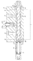
【解決手段】 スプール12の両端に連通溝20,21を形成し、これら連通溝20,21はスプールが図示のノーマル位置にあるとき、パイロット室14,15にそれぞれ連通する。そして、スプール12が例えば図面右方向に移動したとき、一方の連通溝20と信号圧通路18とが連通状態を保って、他方の連通溝21が信号圧通路19から離隔する。反対にスプール12が図面左方向に移動すると、他方の連通溝21と信号圧通路19とが連通状態を保って、一方の連通溝20が信号圧通路18から離隔する。
【選択図】 図1
Description
この従来の制御弁は、その弁本体1にスプール2を摺動自在に組み込むとともに、このスプール2にはセンタリングスプリング3のばね力を作用させている。このようにしたスプール2の両端はパイロット室4,5に臨ませ、いずれか一方のパイロット室4あるいは5に導かれたパイロット圧の作用でスプール2が切り換わり、弁本体1に形成した一対のアクチュエータポート6,7のうち、いずれか一方のアクチュエータポートを図示していないポンプに連通させ、他方のアクチュエータポートを図示していないタンクに連通させる構成にしている。
このとき、一方のパイロット室4に導かれたパイロット圧は、チェック弁9を押し開いて信号圧通路8に導かれ、この通路8から他の機器に伝達されて、この制御弁に接続した図示していないアクチュエータと、他の機器とを同期させるようにしている。
このとき、他方のパイロット室5に導かれたパイロット圧は、連通孔10からチェック弁11を押し開いて信号圧通路8に導かれ、この通路8から他の機器に伝達される。
しかも、上記従来の制御弁の場合には、パイロット室同士の連通を遮断するために2つのチェック弁を必要とするので、その分、部品点数が多くなるという問題もあった。
しかも、スプールがパイロット室の圧力作用でいずれかに移動したときにも、この一方のパイロット室と信号圧通路とは上記連通溝を介して連通し、他方のパイロット室と信号圧通路との連通が遮断されるので、他の機器には信号圧通路を介して確実に信号圧が伝達される。
第3の発明によれば、連通溝を形成するためにスプールをわざわざ長くしなくてもよいので、全体を小型化できる。
一方のパイロット室14にパイロット圧を導くと、そのパイロット圧の作用でスプール12が図面右方向に移動して、他方のアクチュエータポート17を図示していないポンプに連通し、一方のアクチュエータポート16を図示していないタンクに連通する。
そして、このときには連通溝20と信号圧通路18とが連通状態を保っているので、パイロット室14の圧力は連通溝20を介して信号圧通路18に導かれる。しかし、他方の連通溝21は上記スプール12の右方向の移動にともなって信号圧通路19から離隔するので、一方のパイロット室14の圧力が、他方のパイロット室15からタンクに抜けてしまうことはない。
したがって、信号圧通路18,19に圧力がこもったりせず、この信号圧通路18,19に接続した他の機器を誤動作させることもない。
そして、このときには連通溝21が信号圧通路19との連通状態を保っているので、パイロット室15の圧力は連通溝21を介して信号圧通路19に導かれる。しかし、連通溝20は上記スプール12の左方向の移動にともなって信号圧通路18から離隔するので、他方のパイロット室15の圧力が、一方のパイロット室14からタンクに抜けてしまうことはない。
したがって、信号圧通路18,19に圧力がこもったりせず、この信号圧通路18,19に接続した他の機器を誤動作させることもない。
さらに、スプール12が他方のパイロット室15の圧力作用で図面左方向に移動したとき、他方の連通溝23が信号圧通路24との連通状態を保つとともに、一方の連通溝22が信号圧通路24から離隔する。
なお、一つの信号圧通路24を挟んでその両側に連通溝22,23を設け、連通溝23をスプール12に形成した連通孔25を介して他方のパイロット室15に連通させた構成以外は第1実施形態と同じである。
一方のパイロット室14にパイロット圧を導くと、そのパイロット圧の作用でスプール12が図面右方向に移動して、他方のアクチュエータポート17を図示していないポンプに連通し、一方のアクチュエータポート16を図示していないタンクに連通する。
したがって、信号圧通路24に圧力がこもったりせず、この信号圧通路24に接続した他の機器を誤動作させることもない。
したがって、信号圧通路24に圧力がこもったりせず、この信号圧通路24に接続した他の機器を誤動作させることもない。
12 スプール
14,15 パイロット室
18,19 信号圧通路
20,21 連通溝
22,23 連通溝
24 信号圧通路
25 連通孔
Claims (3)
- 弁本体に、スプールを摺動自在に設けるとともに、このスプールの両端をパイロット室に臨ませ、これらいずれか一方のパイロット室に導かれたパイロット圧の作用で上記スプールが切り換わる一方、上記パイロット室のパイロット圧を他の機器の信号圧として導く信号圧通路を設けた制御弁において、上記スプールには一対の連通溝を形成し、これら一対の連通溝は、スプールがノーマル位置にあるとき上記パイロット室と上記信号圧通路とを連通させる一方、一方の連通溝は、スプールが一方に移動したとき信号圧通路との連通状態を保って一方のパイロット室と信号圧通路とを連通させ、スプールが他方に移動したとき信号圧通路と離隔して一方のパイロット室と信号圧通路との連通を遮断する一方、他方の連通溝は、スプールが他方に移動したとき信号圧通路との連通状態を保って他方のパイロット室と信号圧通路とを連通させ、スプールが一方に移動したとき信号圧通路と離隔して他方のパイロット室と信号圧通路との連通を遮断する構成にした制御弁。
- 上記スプールの両端それぞれに上記連通溝を形成し、弁本体にはこれら連通溝に対応させた信号圧通路を形成するとともに、両信号圧通路を下流側において合流させてなる請求項1記載の制御弁。
- 上記スプールの一端に一方の連通溝を形成し、他方の連通溝を一つの信号圧通路を挟んで反対側に形成するとともに、スプールがノーマル位置にあるとき両連通溝が信号圧通路に連通する構成にし、スプールが一方に移動したとき一方の連通溝が信号圧通路と連通状態を保つとともに他方の連通溝が信号圧通路から離隔し、スプールが他方に移動したとき他方の連通溝と信号圧通路との連通状態を保つとともに一方の連通溝が信号圧通路から離隔する構成にする一方、一方の連通溝は一方のパイロット室に開口させ、他方の連通溝はスプールに形成した連通孔を介して他方のパイロット室に連通させた請求項1記載の制御弁。
Priority Applications (6)
| Application Number | Priority Date | Filing Date | Title |
|---|---|---|---|
| JP2011057662A JP5602073B2 (ja) | 2011-03-16 | 2011-03-16 | 制御弁 |
| EP12758307.8A EP2687765B1 (en) | 2011-03-16 | 2012-01-27 | Control valve |
| PCT/JP2012/051773 WO2012124385A1 (ja) | 2011-03-16 | 2012-01-27 | 制御弁 |
| CN201280003109.XA CN103140706B (zh) | 2011-03-16 | 2012-01-27 | 控制阀 |
| US13/696,389 US8844899B2 (en) | 2011-03-16 | 2012-01-27 | Control valve |
| KR1020127028897A KR101397218B1 (ko) | 2011-03-16 | 2012-01-27 | 제어 밸브 |
Applications Claiming Priority (1)
| Application Number | Priority Date | Filing Date | Title |
|---|---|---|---|
| JP2011057662A JP5602073B2 (ja) | 2011-03-16 | 2011-03-16 | 制御弁 |
Publications (2)
| Publication Number | Publication Date |
|---|---|
| JP2012193788A true JP2012193788A (ja) | 2012-10-11 |
| JP5602073B2 JP5602073B2 (ja) | 2014-10-08 |
Family
ID=46830466
Family Applications (1)
| Application Number | Title | Priority Date | Filing Date |
|---|---|---|---|
| JP2011057662A Expired - Fee Related JP5602073B2 (ja) | 2011-03-16 | 2011-03-16 | 制御弁 |
Country Status (6)
| Country | Link |
|---|---|
| US (1) | US8844899B2 (ja) |
| EP (1) | EP2687765B1 (ja) |
| JP (1) | JP5602073B2 (ja) |
| KR (1) | KR101397218B1 (ja) |
| CN (1) | CN103140706B (ja) |
| WO (1) | WO2012124385A1 (ja) |
Families Citing this family (6)
| Publication number | Priority date | Publication date | Assignee | Title |
|---|---|---|---|---|
| JP5602074B2 (ja) * | 2011-03-16 | 2014-10-08 | カヤバ工業株式会社 | 制御弁 |
| US9556970B2 (en) * | 2013-07-19 | 2017-01-31 | Control Components, Inc. | Cascade trim for control valve |
| US10281934B2 (en) * | 2016-06-16 | 2019-05-07 | Parker-Hannifin Corporation | Hydraulic control valve with controlled flow and valve safety disable |
| US11255354B2 (en) * | 2018-03-09 | 2022-02-22 | Kyb Corporation | Control valve |
| JP7139297B2 (ja) * | 2019-09-25 | 2022-09-20 | 日立建機株式会社 | 流量制御弁 |
| US12595854B2 (en) * | 2024-09-17 | 2026-04-07 | Hamilton Sundstrand Corporation | Compact hydraulically centered three-way transfer valve |
Citations (7)
| Publication number | Priority date | Publication date | Assignee | Title |
|---|---|---|---|---|
| JPS6256602A (ja) * | 1985-09-05 | 1987-03-12 | Yutani Juko Kk | 切換弁 |
| JPH11141696A (ja) * | 1997-11-10 | 1999-05-25 | Hitachi Constr Mach Co Ltd | スプール型方向切換弁システム |
| JPH11280705A (ja) * | 1998-03-27 | 1999-10-15 | Shin Caterpillar Mitsubishi Ltd | 油圧弁操作装置 |
| JP2000097210A (ja) * | 1998-09-18 | 2000-04-04 | Kayaba Ind Co Ltd | 油圧制御装置 |
| JP2001221357A (ja) * | 2000-02-09 | 2001-08-17 | Kayaba Ind Co Ltd | 積層バルブ |
| JP2001241559A (ja) * | 2000-03-01 | 2001-09-07 | Aichi Corp | スプール弁 |
| JP2009013753A (ja) * | 2007-07-09 | 2009-01-22 | Kayaba Ind Co Ltd | 建設機械用車両の走行制御装置 |
Family Cites Families (7)
| Publication number | Priority date | Publication date | Assignee | Title |
|---|---|---|---|---|
| US2157240A (en) * | 1935-02-21 | 1939-05-09 | Ex Cell O Corp | Valve structure |
| US2634086A (en) * | 1950-08-15 | 1953-04-07 | Sundstrand Machine Tool Co | Valve with self-contained stem centering device |
| US2841168A (en) * | 1952-11-19 | 1958-07-01 | Kleelavite Company Ltd | Hydraulic control valve apparatus |
| US3023781A (en) * | 1958-05-09 | 1962-03-06 | Raytheon Co | Hydraulic servo valves |
| US3160174A (en) * | 1961-03-28 | 1964-12-08 | Parker Hannifin Corp | Remote power shift circuits for spool valves and the like |
| US5313983A (en) * | 1993-03-29 | 1994-05-24 | Dana Corporation | Remote hydraulic control systems |
| KR100631067B1 (ko) * | 2004-05-04 | 2006-10-02 | 볼보 컨스트럭션 이키프먼트 홀딩 스웨덴 에이비 | 홀딩밸브의 응답성이 개선된 유압제어밸브 |
-
2011
- 2011-03-16 JP JP2011057662A patent/JP5602073B2/ja not_active Expired - Fee Related
-
2012
- 2012-01-27 EP EP12758307.8A patent/EP2687765B1/en not_active Not-in-force
- 2012-01-27 WO PCT/JP2012/051773 patent/WO2012124385A1/ja not_active Ceased
- 2012-01-27 US US13/696,389 patent/US8844899B2/en not_active Expired - Fee Related
- 2012-01-27 KR KR1020127028897A patent/KR101397218B1/ko not_active Expired - Fee Related
- 2012-01-27 CN CN201280003109.XA patent/CN103140706B/zh not_active Expired - Fee Related
Patent Citations (7)
| Publication number | Priority date | Publication date | Assignee | Title |
|---|---|---|---|---|
| JPS6256602A (ja) * | 1985-09-05 | 1987-03-12 | Yutani Juko Kk | 切換弁 |
| JPH11141696A (ja) * | 1997-11-10 | 1999-05-25 | Hitachi Constr Mach Co Ltd | スプール型方向切換弁システム |
| JPH11280705A (ja) * | 1998-03-27 | 1999-10-15 | Shin Caterpillar Mitsubishi Ltd | 油圧弁操作装置 |
| JP2000097210A (ja) * | 1998-09-18 | 2000-04-04 | Kayaba Ind Co Ltd | 油圧制御装置 |
| JP2001221357A (ja) * | 2000-02-09 | 2001-08-17 | Kayaba Ind Co Ltd | 積層バルブ |
| JP2001241559A (ja) * | 2000-03-01 | 2001-09-07 | Aichi Corp | スプール弁 |
| JP2009013753A (ja) * | 2007-07-09 | 2009-01-22 | Kayaba Ind Co Ltd | 建設機械用車両の走行制御装置 |
Also Published As
| Publication number | Publication date |
|---|---|
| EP2687765A4 (en) | 2014-11-12 |
| EP2687765B1 (en) | 2017-08-16 |
| CN103140706A (zh) | 2013-06-05 |
| KR20130004511A (ko) | 2013-01-10 |
| EP2687765A1 (en) | 2014-01-22 |
| JP5602073B2 (ja) | 2014-10-08 |
| CN103140706B (zh) | 2014-07-30 |
| WO2012124385A1 (ja) | 2012-09-20 |
| US8844899B2 (en) | 2014-09-30 |
| KR101397218B1 (ko) | 2014-05-20 |
| US20130048889A1 (en) | 2013-02-28 |
Similar Documents
| Publication | Publication Date | Title |
|---|---|---|
| JP5602074B2 (ja) | 制御弁 | |
| JP5602073B2 (ja) | 制御弁 | |
| KR20120115111A (ko) | 파일럿식 3위치 스위칭 밸브 | |
| CN104421463A (zh) | 带残压排气阀的五口切换阀 | |
| KR101541684B1 (ko) | 유압 제어 장치 | |
| JP2009013753A (ja) | 建設機械用車両の走行制御装置 | |
| JP6355606B2 (ja) | ロードセンシング回路におけるバルブ構造 | |
| JP5730369B2 (ja) | 切換弁 | |
| JP6284469B2 (ja) | 油圧回路 | |
| JP6200634B2 (ja) | 油圧制御弁 | |
| JP2008175281A (ja) | 油圧制御装置 | |
| JP6045419B2 (ja) | 油圧制御装置 | |
| JP5822232B2 (ja) | 切換弁 | |
| JP4907143B2 (ja) | バルブ構造 | |
| JP4020878B2 (ja) | 油圧制御装置 | |
| JP2019157949A (ja) | 制御弁 | |
| WO2019053783A1 (ja) | コントロールバルブ | |
| JP2008008386A (ja) | 多連形切換弁 | |
| WO2015049728A1 (ja) | 流量制御弁 | |
| JP2004270776A (ja) | 多連弁装置 |
Legal Events
| Date | Code | Title | Description |
|---|---|---|---|
| A621 | Written request for application examination |
Free format text: JAPANESE INTERMEDIATE CODE: A621 Effective date: 20131126 |
|
| TRDD | Decision of grant or rejection written | ||
| A01 | Written decision to grant a patent or to grant a registration (utility model) |
Free format text: JAPANESE INTERMEDIATE CODE: A01 Effective date: 20140729 |
|
| A61 | First payment of annual fees (during grant procedure) |
Free format text: JAPANESE INTERMEDIATE CODE: A61 Effective date: 20140819 |
|
| R151 | Written notification of patent or utility model registration |
Ref document number: 5602073 Country of ref document: JP Free format text: JAPANESE INTERMEDIATE CODE: R151 |
|
| S533 | Written request for registration of change of name |
Free format text: JAPANESE INTERMEDIATE CODE: R313533 |
|
| R350 | Written notification of registration of transfer |
Free format text: JAPANESE INTERMEDIATE CODE: R350 |
|
| R250 | Receipt of annual fees |
Free format text: JAPANESE INTERMEDIATE CODE: R250 |
|
| LAPS | Cancellation because of no payment of annual fees |