JP2013201901A - 田植機 - Google Patents
田植機 Download PDFInfo
- Publication number
- JP2013201901A JP2013201901A JP2012070645A JP2012070645A JP2013201901A JP 2013201901 A JP2013201901 A JP 2013201901A JP 2012070645 A JP2012070645 A JP 2012070645A JP 2012070645 A JP2012070645 A JP 2012070645A JP 2013201901 A JP2013201901 A JP 2013201901A
- Authority
- JP
- Japan
- Prior art keywords
- engine
- exhaust
- suction fan
- fan
- machine body
- Prior art date
- Legal status (The legal status is an assumption and is not a legal conclusion. Google has not performed a legal analysis and makes no representation as to the accuracy of the status listed.)
- Granted
Links
- 235000007164 Oryza sativa Nutrition 0.000 title claims abstract description 30
- 235000009566 rice Nutrition 0.000 title claims abstract description 30
- 240000007594 Oryza sativa Species 0.000 title 1
- 238000001816 cooling Methods 0.000 claims abstract description 79
- 230000005540 biological transmission Effects 0.000 claims abstract description 56
- 241000209094 Oryza Species 0.000 claims abstract description 29
- 230000002093 peripheral effect Effects 0.000 abstract description 6
- 239000003921 oil Substances 0.000 description 34
- 238000009423 ventilation Methods 0.000 description 22
- 230000000694 effects Effects 0.000 description 10
- 239000003550 marker Substances 0.000 description 8
- 239000010705 motor oil Substances 0.000 description 8
- 230000007246 mechanism Effects 0.000 description 5
- 230000002411 adverse Effects 0.000 description 4
- 238000003466 welding Methods 0.000 description 4
- 210000000078 claw Anatomy 0.000 description 3
- 230000006866 deterioration Effects 0.000 description 3
- 229920001971 elastomer Polymers 0.000 description 3
- 239000005060 rubber Substances 0.000 description 3
- 238000004891 communication Methods 0.000 description 2
- 239000002184 metal Substances 0.000 description 2
- 230000009466 transformation Effects 0.000 description 2
- 241000196324 Embryophyta Species 0.000 description 1
- 230000008901 benefit Effects 0.000 description 1
- 230000015556 catabolic process Effects 0.000 description 1
- 230000008859 change Effects 0.000 description 1
- 230000007423 decrease Effects 0.000 description 1
- 238000006731 degradation reaction Methods 0.000 description 1
- 238000005516 engineering process Methods 0.000 description 1
- 238000002955 isolation Methods 0.000 description 1
- 238000000034 method Methods 0.000 description 1
- 238000012986 modification Methods 0.000 description 1
- 230000004048 modification Effects 0.000 description 1
- 210000003205 muscle Anatomy 0.000 description 1
- 230000000149 penetrating effect Effects 0.000 description 1
- 230000008569 process Effects 0.000 description 1
- 238000004080 punching Methods 0.000 description 1
- 238000000926 separation method Methods 0.000 description 1
- 230000001502 supplementing effect Effects 0.000 description 1
- 239000013585 weight reducing agent Substances 0.000 description 1
Images





Landscapes
- Arrangement Or Mounting Of Propulsion Units For Vehicles (AREA)
Abstract
【解決手段】本願発明の田植機1は、走行機体2に搭載されたエンジン5と、前記エンジン5の動力を変速して前記走行機体2の走行部3,4に伝達するミッションケース6と、前記走行機体2に装着された苗植付装置23とを備える。前記エンジン5の一側面にエンジン空冷用の吸引ファン71を設ける。前記走行機体2を構成する左右一対の機体フレーム50の間に、前記エンジン5を前記両機体フレーム50よりも下側に突出するように配置する。前記エンジン5を上方から覆うフロントボンネット11よりも下側で、前記吸引ファン71に対峙させてオイルクーラ79を配置する。
【選択図】図7
Description
まず、図1及び図2を参照しながら、田植機1の概要について説明する。実施形態の田植機1は、走行部としての左右一対の前車輪3及び同じく左右一対の後車輪4によって支持された走行機体2を備えている。走行機体2の前部にはエンジン5が搭載され、エンジン5からの動力をこの後方のミッションケース6に伝達して、前車輪3及び後車輪4を駆動させることにより、前後進走行するように構成されている。ミッションケース6の左右側方にフロントアクスルケース7を突出させ、フロントアクスルケース7から左右外向きに延びる前車軸に前車輪3が舵取り可能に取り付けられている。ミッションケース6の後方に筒状フレーム8を突出させ、筒状フレーム8の後端側にリヤアクスルケース9を固設し、リヤアクスルケース9から左右外向きに延びる後車軸に後車輪4が取り付けられている。
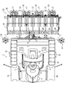
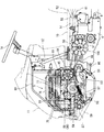
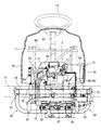
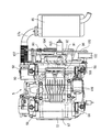
次に、図3〜図12を参照しながら、走行機体2に対するエンジン5の支持構造並びにエンジン5周辺構造について説明する。図3及び図4に示すように、走行機体2は前後に延びる左右一対の機体フレーム50を備えている。各機体フレーム50は前部フレーム51と後部フレーム52とに二分割されている。前部フレーム51の後端部と後部フレーム52の前端部とが左右横長の中間連結フレーム53に溶接固定されている。左右一対の前部フレーム51の前端部は前フレーム54に溶接固定されている。左右一対の後部フレーム52の後端側は後フレーム55に溶接固定されている。前フレーム54、左右両前部フレーム51及び中間連結フレーム53は平面視四角枠状に構成されている。同様に、中間連結フレーム53、左右両後部フレーム52及び後フレーム55も平面視四角枠状に構成されている。
上記の実施形態によると、走行機体2に搭載されたエンジン5と、前記エンジン5の動力を変速して前記走行機体2の走行部3,4に伝達するミッションケース6と、前記走行機体2に装着された苗植付装置23とを備えており、前記エンジン5の一側面にエンジン空冷用の吸引ファン71が設けられている田植機1であって、前記エンジン5のうち前記吸引ファン71と反対側の他側面には、前記他側面から突出した出力軸70を挟んで一方に、前記エンジン5の排気系に連通する排気管87(87b)を延長させ、他方にはジェネレータ94が配置されているから、前記出力軸70を挟んだ両側に前記排気管87(87b)と前記ジェネレータ94とを振り分けて、前記排気管87(87b)の熱による前記ジェネレータ94への悪影響を抑制しながら、前記エンジン5の他側面側に前記排気管87(87b)と前記ジェネレータ94とをコンパクトにまとめて配置できる。
本願発明は、前述の実施形態に限らず、様々な態様に具体化できる。各部の構成は図示の実施形態に限定されるものではなく、本願発明の趣旨を逸脱しない範囲で種々変更が可能である。
2 走行機体
5 エンジン
6 ミッションケース
23 苗植付装置
50 機体フレーム
57 エンジン台
58 防振ゴム
70 出力軸
71 吸引ファン
75 流通口
76 クリーナケース
77 上部通風路
79 第2オイルクーラ
80 ボンネットフレーム
83 電装部品
84 通風ダクト
85 上部排風路
86 下部排風路
87 排気管
88 遮蔽カバー
91 排出ファン
94 ジェネレータ
95 固定ブラケット
96,99 伝達ベルト
98 ミッション入力プーリ
101 張力付与部材
108 抜き穴
Claims (3)
- 走行機体に搭載されたエンジンと、前記エンジンの動力を変速して前記走行機体の走行部に伝達するミッションケースと、前記走行機体に装着された苗植付装置とを備えており、前記エンジンの一側面にエンジン空冷用の吸引ファンが設けられている田植機であって、
前記走行機体を構成する左右一対の機体フレームの間に、前記エンジンが前記両機体フレームよりも下側に突出するように配置されており、
前記エンジンを上方から覆うフロントボンネットよりも下側で、前記吸引ファンに対峙させてオイルクーラが配置されている、
田植機。 - 前記フロントボンネットの下部側に形成された流通口に、前記オイルクーラの上方に配置された電装部品を臨ませ、
前記エンジンを取り囲むように前記フロントボンネット内に設けられたボンネットフレームに、前記オイルクーラ及び前記電装部品を支持させている、
請求項1に記載の田植機。 - 前記エンジンのうち前記吸引ファンと反対側の他側面に、前記吸引ファンとは別個に、排出ファンが設けられている、
請求項1又は2に記載の田植機。
Priority Applications (5)
| Application Number | Priority Date | Filing Date | Title |
|---|---|---|---|
| JP2012070645A JP5964100B2 (ja) | 2012-03-27 | 2012-03-27 | 田植機 |
| IN7465DEN2014 IN2014DN07465A (ja) | 2012-03-27 | 2013-03-19 | |
| KR1020147025543A KR20140138717A (ko) | 2012-03-27 | 2013-03-19 | 이앙기 |
| PCT/JP2013/057837 WO2013146475A1 (ja) | 2012-03-27 | 2013-03-19 | 田植機 |
| CN201380016705.6A CN104219944B (zh) | 2012-03-27 | 2013-03-19 | 插秧机 |
Applications Claiming Priority (1)
| Application Number | Priority Date | Filing Date | Title |
|---|---|---|---|
| JP2012070645A JP5964100B2 (ja) | 2012-03-27 | 2012-03-27 | 田植機 |
Publications (2)
| Publication Number | Publication Date |
|---|---|
| JP2013201901A true JP2013201901A (ja) | 2013-10-07 |
| JP5964100B2 JP5964100B2 (ja) | 2016-08-03 |
Family
ID=49521688
Family Applications (1)
| Application Number | Title | Priority Date | Filing Date |
|---|---|---|---|
| JP2012070645A Expired - Fee Related JP5964100B2 (ja) | 2012-03-27 | 2012-03-27 | 田植機 |
Country Status (1)
| Country | Link |
|---|---|
| JP (1) | JP5964100B2 (ja) |
Cited By (1)
| Publication number | Priority date | Publication date | Assignee | Title |
|---|---|---|---|---|
| CN111942136A (zh) * | 2019-05-14 | 2020-11-17 | 陕西保利特种车制造有限公司 | 一种车外可调试的动力总成 |
Citations (5)
| Publication number | Priority date | Publication date | Assignee | Title |
|---|---|---|---|---|
| JPS6343940U (ja) * | 1986-09-08 | 1988-03-24 | ||
| JP2000326738A (ja) * | 1999-05-18 | 2000-11-28 | Kubota Corp | 水田作業機の原動部 |
| JP2003088221A (ja) * | 2001-09-14 | 2003-03-25 | Iseki & Co Ltd | コンバイン |
| JP2004001746A (ja) * | 2003-06-13 | 2004-01-08 | Kubota Corp | 乗用型移植機の原動部構造 |
| JP2010168043A (ja) * | 2010-03-05 | 2010-08-05 | Yanmar Co Ltd | 田植機 |
-
2012
- 2012-03-27 JP JP2012070645A patent/JP5964100B2/ja not_active Expired - Fee Related
Patent Citations (5)
| Publication number | Priority date | Publication date | Assignee | Title |
|---|---|---|---|---|
| JPS6343940U (ja) * | 1986-09-08 | 1988-03-24 | ||
| JP2000326738A (ja) * | 1999-05-18 | 2000-11-28 | Kubota Corp | 水田作業機の原動部 |
| JP2003088221A (ja) * | 2001-09-14 | 2003-03-25 | Iseki & Co Ltd | コンバイン |
| JP2004001746A (ja) * | 2003-06-13 | 2004-01-08 | Kubota Corp | 乗用型移植機の原動部構造 |
| JP2010168043A (ja) * | 2010-03-05 | 2010-08-05 | Yanmar Co Ltd | 田植機 |
Cited By (2)
| Publication number | Priority date | Publication date | Assignee | Title |
|---|---|---|---|---|
| CN111942136A (zh) * | 2019-05-14 | 2020-11-17 | 陕西保利特种车制造有限公司 | 一种车外可调试的动力总成 |
| CN111942136B (zh) * | 2019-05-14 | 2022-04-01 | 陕西保利特种车制造有限公司 | 一种车外可调试的动力总成 |
Also Published As
| Publication number | Publication date |
|---|---|
| JP5964100B2 (ja) | 2016-08-03 |
Similar Documents
| Publication | Publication Date | Title |
|---|---|---|
| JP2001199251A (ja) | 作業車の原動部冷却構造 | |
| JP3862674B2 (ja) | 乗用型移植機 | |
| JP5997469B2 (ja) | 田植機 | |
| JP5288290B2 (ja) | 作業車輌の原動部構造 | |
| WO2013146475A1 (ja) | 田植機 | |
| WO2013146476A1 (ja) | 田植機 | |
| JP5829963B2 (ja) | 田植機 | |
| JP4988888B2 (ja) | 田植機 | |
| JP5844191B2 (ja) | 田植機 | |
| JP5964100B2 (ja) | 田植機 | |
| JP5844192B2 (ja) | 田植機 | |
| JP6015960B2 (ja) | コンバイン | |
| JP5844190B2 (ja) | 田植機 | |
| JP6032569B2 (ja) | 作業車輌の原動部構造 | |
| TWI569715B (zh) | 作業車輛的原動部構造 | |
| JP3599479B2 (ja) | 乗用型移植機 | |
| JP4134596B2 (ja) | スクータ型自動二輪車用ベルト式自動変速機の冷却構造 | |
| JP5765817B2 (ja) | 田植機 | |
| JP5737522B2 (ja) | 作業車両の原動部構造 | |
| JP7243667B2 (ja) | 作業車両 | |
| JP5174075B2 (ja) | 乗用型作業機 | |
| JP4462573B2 (ja) | バーチカルエンジン搭載作業車の冷却機構 | |
| JP2011075106A (ja) | 作業機 |
Legal Events
| Date | Code | Title | Description |
|---|---|---|---|
| A621 | Written request for application examination |
Free format text: JAPANESE INTERMEDIATE CODE: A621 Effective date: 20140806 |
|
| A131 | Notification of reasons for refusal |
Free format text: JAPANESE INTERMEDIATE CODE: A131 Effective date: 20151209 |
|
| A521 | Request for written amendment filed |
Free format text: JAPANESE INTERMEDIATE CODE: A523 Effective date: 20160202 |
|
| TRDD | Decision of grant or rejection written | ||
| A01 | Written decision to grant a patent or to grant a registration (utility model) |
Free format text: JAPANESE INTERMEDIATE CODE: A01 Effective date: 20160622 |
|
| A61 | First payment of annual fees (during grant procedure) |
Free format text: JAPANESE INTERMEDIATE CODE: A61 Effective date: 20160629 |
|
| R150 | Certificate of patent or registration of utility model |
Ref document number: 5964100 Country of ref document: JP Free format text: JAPANESE INTERMEDIATE CODE: R150 |
|
| R250 | Receipt of annual fees |
Free format text: JAPANESE INTERMEDIATE CODE: R250 |
|
| S533 | Written request for registration of change of name |
Free format text: JAPANESE INTERMEDIATE CODE: R313533 |
|
| R350 | Written notification of registration of transfer |
Free format text: JAPANESE INTERMEDIATE CODE: R350 |
|
| LAPS | Cancellation because of no payment of annual fees |