JP2014181802A - 緩衝弁 - Google Patents
緩衝弁 Download PDFInfo
- Publication number
- JP2014181802A JP2014181802A JP2013058256A JP2013058256A JP2014181802A JP 2014181802 A JP2014181802 A JP 2014181802A JP 2013058256 A JP2013058256 A JP 2013058256A JP 2013058256 A JP2013058256 A JP 2013058256A JP 2014181802 A JP2014181802 A JP 2014181802A
- Authority
- JP
- Japan
- Prior art keywords
- spool
- pair
- primary
- chamber
- spools
- Prior art date
- Legal status (The legal status is an assumption and is not a legal conclusion. Google has not performed a legal analysis and makes no representation as to the accuracy of the status listed.)
- Granted
Links
Images


Classifications
-
- F—MECHANICAL ENGINEERING; LIGHTING; HEATING; WEAPONS; BLASTING
- F15—FLUID-PRESSURE ACTUATORS; HYDRAULICS OR PNEUMATICS IN GENERAL
- F15B—SYSTEMS ACTING BY MEANS OF FLUIDS IN GENERAL; FLUID-PRESSURE ACTUATORS, e.g. SERVOMOTORS; DETAILS OF FLUID-PRESSURE SYSTEMS, NOT OTHERWISE PROVIDED FOR
- F15B13/00—Details of servomotor systems ; Valves for servomotor systems
- F15B13/02—Fluid distribution or supply devices characterised by their adaptation to the control of servomotors
- F15B13/04—Fluid distribution or supply devices characterised by their adaptation to the control of servomotors for use with a single servomotor
- F15B13/042—Fluid distribution or supply devices characterised by their adaptation to the control of servomotors for use with a single servomotor operated by fluid pressure
- F15B13/0422—Fluid distribution or supply devices characterised by their adaptation to the control of servomotors for use with a single servomotor operated by fluid pressure with manually-operated pilot valves, e.g. joysticks
-
- F—MECHANICAL ENGINEERING; LIGHTING; HEATING; WEAPONS; BLASTING
- F16—ENGINEERING ELEMENTS AND UNITS; GENERAL MEASURES FOR PRODUCING AND MAINTAINING EFFECTIVE FUNCTIONING OF MACHINES OR INSTALLATIONS; THERMAL INSULATION IN GENERAL
- F16K—VALVES; TAPS; COCKS; ACTUATING-FLOATS; DEVICES FOR VENTING OR AERATING
- F16K47/00—Means in valves for absorbing fluid energy
- F16K47/02—Means in valves for absorbing fluid energy for preventing water-hammer or noise
- F16K47/023—Means in valves for absorbing fluid energy for preventing water-hammer or noise for preventing water-hammer, e.g. damping of the valve movement
-
- F—MECHANICAL ENGINEERING; LIGHTING; HEATING; WEAPONS; BLASTING
- F15—FLUID-PRESSURE ACTUATORS; HYDRAULICS OR PNEUMATICS IN GENERAL
- F15B—SYSTEMS ACTING BY MEANS OF FLUIDS IN GENERAL; FLUID-PRESSURE ACTUATORS, e.g. SERVOMOTORS; DETAILS OF FLUID-PRESSURE SYSTEMS, NOT OTHERWISE PROVIDED FOR
- F15B13/00—Details of servomotor systems ; Valves for servomotor systems
- F15B13/02—Fluid distribution or supply devices characterised by their adaptation to the control of servomotors
- F15B13/04—Fluid distribution or supply devices characterised by their adaptation to the control of servomotors for use with a single servomotor
- F15B13/0401—Valve members; Fluid interconnections therefor
- F15B13/0402—Valve members; Fluid interconnections therefor for linearly sliding valves, e.g. spool valves
-
- F—MECHANICAL ENGINEERING; LIGHTING; HEATING; WEAPONS; BLASTING
- F15—FLUID-PRESSURE ACTUATORS; HYDRAULICS OR PNEUMATICS IN GENERAL
- F15B—SYSTEMS ACTING BY MEANS OF FLUIDS IN GENERAL; FLUID-PRESSURE ACTUATORS, e.g. SERVOMOTORS; DETAILS OF FLUID-PRESSURE SYSTEMS, NOT OTHERWISE PROVIDED FOR
- F15B13/00—Details of servomotor systems ; Valves for servomotor systems
- F15B13/02—Fluid distribution or supply devices characterised by their adaptation to the control of servomotors
- F15B13/04—Fluid distribution or supply devices characterised by their adaptation to the control of servomotors for use with a single servomotor
- F15B13/0401—Valve members; Fluid interconnections therefor
- F15B13/0407—Means for damping the valve member movement
-
- F—MECHANICAL ENGINEERING; LIGHTING; HEATING; WEAPONS; BLASTING
- F16—ENGINEERING ELEMENTS AND UNITS; GENERAL MEASURES FOR PRODUCING AND MAINTAINING EFFECTIVE FUNCTIONING OF MACHINES OR INSTALLATIONS; THERMAL INSULATION IN GENERAL
- F16K—VALVES; TAPS; COCKS; ACTUATING-FLOATS; DEVICES FOR VENTING OR AERATING
- F16K11/00—Multiple-way valves, e.g. mixing valves; Pipe fittings incorporating such valves
- F16K11/10—Multiple-way valves, e.g. mixing valves; Pipe fittings incorporating such valves with two or more closure members not moving as a unit
-
- F—MECHANICAL ENGINEERING; LIGHTING; HEATING; WEAPONS; BLASTING
- F16—ENGINEERING ELEMENTS AND UNITS; GENERAL MEASURES FOR PRODUCING AND MAINTAINING EFFECTIVE FUNCTIONING OF MACHINES OR INSTALLATIONS; THERMAL INSULATION IN GENERAL
- F16K—VALVES; TAPS; COCKS; ACTUATING-FLOATS; DEVICES FOR VENTING OR AERATING
- F16K47/00—Means in valves for absorbing fluid energy
- F16K47/04—Means in valves for absorbing fluid energy for decreasing pressure or noise level, the throttle being incorporated in the closure member
-
- F—MECHANICAL ENGINEERING; LIGHTING; HEATING; WEAPONS; BLASTING
- F15—FLUID-PRESSURE ACTUATORS; HYDRAULICS OR PNEUMATICS IN GENERAL
- F15B—SYSTEMS ACTING BY MEANS OF FLUIDS IN GENERAL; FLUID-PRESSURE ACTUATORS, e.g. SERVOMOTORS; DETAILS OF FLUID-PRESSURE SYSTEMS, NOT OTHERWISE PROVIDED FOR
- F15B2211/00—Circuits for servomotor systems
- F15B2211/60—Circuit components or control therefor
- F15B2211/635—Circuits providing pilot pressure to pilot pressure-controlled fluid circuit elements
- F15B2211/6355—Circuits providing pilot pressure to pilot pressure-controlled fluid circuit elements having valve means
-
- F—MECHANICAL ENGINEERING; LIGHTING; HEATING; WEAPONS; BLASTING
- F15—FLUID-PRESSURE ACTUATORS; HYDRAULICS OR PNEUMATICS IN GENERAL
- F15B—SYSTEMS ACTING BY MEANS OF FLUIDS IN GENERAL; FLUID-PRESSURE ACTUATORS, e.g. SERVOMOTORS; DETAILS OF FLUID-PRESSURE SYSTEMS, NOT OTHERWISE PROVIDED FOR
- F15B2211/00—Circuits for servomotor systems
- F15B2211/60—Circuit components or control therefor
- F15B2211/67—Methods for controlling pilot pressure
-
- F—MECHANICAL ENGINEERING; LIGHTING; HEATING; WEAPONS; BLASTING
- F15—FLUID-PRESSURE ACTUATORS; HYDRAULICS OR PNEUMATICS IN GENERAL
- F15B—SYSTEMS ACTING BY MEANS OF FLUIDS IN GENERAL; FLUID-PRESSURE ACTUATORS, e.g. SERVOMOTORS; DETAILS OF FLUID-PRESSURE SYSTEMS, NOT OTHERWISE PROVIDED FOR
- F15B2211/00—Circuits for servomotor systems
- F15B2211/80—Other types of control related to particular problems or conditions
- F15B2211/86—Control during or prevention of abnormal conditions
- F15B2211/8606—Control during or prevention of abnormal conditions the abnormal condition being a shock
-
- Y—GENERAL TAGGING OF NEW TECHNOLOGICAL DEVELOPMENTS; GENERAL TAGGING OF CROSS-SECTIONAL TECHNOLOGIES SPANNING OVER SEVERAL SECTIONS OF THE IPC; TECHNICAL SUBJECTS COVERED BY FORMER USPC CROSS-REFERENCE ART COLLECTIONS [XRACs] AND DIGESTS
- Y10—TECHNICAL SUBJECTS COVERED BY FORMER USPC
- Y10T—TECHNICAL SUBJECTS COVERED BY FORMER US CLASSIFICATION
- Y10T137/00—Fluid handling
- Y10T137/8593—Systems
- Y10T137/87169—Supply and exhaust
- Y10T137/87193—Pilot-actuated
Landscapes
- Engineering & Computer Science (AREA)
- General Engineering & Computer Science (AREA)
- Mechanical Engineering (AREA)
- Physics & Mathematics (AREA)
- Fluid Mechanics (AREA)
- Multiple-Way Valves (AREA)
- Sliding Valves (AREA)
- Details Of Valves (AREA)
- Mining & Mineral Resources (AREA)
- Civil Engineering (AREA)
- Structural Engineering (AREA)
Abstract
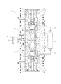
【解決手段】緩衝弁1は、一対の一次室25A,25Bおよび一対の二次室26A,26Bを有するハウジング2を備えている。ハウジング2内には、第1スプール3および一対の第2スプール4A,4Bが配置され、それらの間には付勢部材6が配置されている。第1スプール3には、タンクポート23と連通する第1内部通路35が形成されている。各第2スプールは、一次室と二次室との間に形成された開口(27Aまたは27B)を開閉するランド部43を有し、各第2スプールには、絞り46を有する第2内部通路45が形成されている。一方の第2スプールが第1スプール3に向かって移動すると、第1内部通路35が他方の第2スプール側の二次室と連通する。
【選択図】図1
Description
本発明は上述した実施形態に限定されるものではなく、本発明の要旨を逸脱しない範囲で種々の変形が可能である。
2 ハウジング
21A,21B 一次ポート
22A,22B 二次ポート
23 タンクポート
25A,25B 一次室
26A,26B 二次室
27A,27B 連通路
3 第1スプール
35 第1内部通路
4A,4B 第2スプール
43 ランド部
45 第2内部通路
46 絞り
6 付勢部材
Claims (4)
- 一対の一次ポートと連通する一対の一次室、および前記一対の一次室の内側に一対の二次ポートと連通する一対の二次室を有し、前記一対の二次室の間にタンクポートが形成されたハウジングと、
前記一対の二次室に跨って延びる第1スプールであって前記タンクポートと連通する第1内部通路が形成された第1スプールと、
前記第1スプールの両側に配置された、各々が、前記一次室と前記二次室との間に形成された開口を開閉するランド部を有する一対の第2スプールであって、各々に、絞りを有する第2内部通路が前記一次室と前記二次室とをつなぐように形成された第2スプールと、
前記第1スプールと前記一対の第2スプールのそれぞれとの間に配置された、それらを互いに離間する方向に付勢する付勢部材と、を備え、
前記一対の第2スプールの一方が前記第1スプールに向かって移動したときに、前記第1スプールが中立位置から前記一対の第2スプールの他方に向かって移動して、前記第1内部通路が前記一対の第2スプールの他方側の前記二次室に連通する、緩衝弁。 - 前記第1スプールおよび前記一対の第2スプールが並ぶ方向から見たときに、前記ランド部の投影面積は、前記第1スプールの投影面積よりも大きい、請求項1に記載の緩衝弁。
- 前記開口は円筒面により規定されており、前記開口に摺接する前記ランド部は円盤状であり、
前記第1スプールは断面円形状の棒状であり、
前記ランド部の直径は、前記第1スプールの最大径よりも大きい、請求項2に記載の緩衝弁。 - 前記第1スプールは、その軸方向に分割された2つのスプール体によって形成されている、請求項1乃至3の何れか一項に記載の緩衝弁。
Priority Applications (7)
| Application Number | Priority Date | Filing Date | Title |
|---|---|---|---|
| JP2013058256A JP5848721B2 (ja) | 2013-03-21 | 2013-03-21 | 緩衝弁 |
| CA2872605A CA2872605A1 (en) | 2013-03-21 | 2014-03-07 | Cushion valve |
| CN201480002073.2A CN104508344B (zh) | 2013-03-21 | 2014-03-07 | 缓冲阀 |
| EP14768244.7A EP2977659A1 (en) | 2013-03-21 | 2014-03-07 | Shock-absorbing valve |
| KR1020157013603A KR20150074164A (ko) | 2013-03-21 | 2014-03-07 | 완충 밸브 |
| US14/406,787 US20150144212A1 (en) | 2013-03-21 | 2014-03-07 | Cushion valve |
| PCT/JP2014/001275 WO2014147987A1 (ja) | 2013-03-21 | 2014-03-07 | 緩衝弁 |
Applications Claiming Priority (1)
| Application Number | Priority Date | Filing Date | Title |
|---|---|---|---|
| JP2013058256A JP5848721B2 (ja) | 2013-03-21 | 2013-03-21 | 緩衝弁 |
Publications (2)
| Publication Number | Publication Date |
|---|---|
| JP2014181802A true JP2014181802A (ja) | 2014-09-29 |
| JP5848721B2 JP5848721B2 (ja) | 2016-01-27 |
Family
ID=51579688
Family Applications (1)
| Application Number | Title | Priority Date | Filing Date |
|---|---|---|---|
| JP2013058256A Active JP5848721B2 (ja) | 2013-03-21 | 2013-03-21 | 緩衝弁 |
Country Status (7)
| Country | Link |
|---|---|
| US (1) | US20150144212A1 (ja) |
| EP (1) | EP2977659A1 (ja) |
| JP (1) | JP5848721B2 (ja) |
| KR (1) | KR20150074164A (ja) |
| CN (1) | CN104508344B (ja) |
| CA (1) | CA2872605A1 (ja) |
| WO (1) | WO2014147987A1 (ja) |
Cited By (1)
| Publication number | Priority date | Publication date | Assignee | Title |
|---|---|---|---|---|
| CN104930004A (zh) * | 2015-05-27 | 2015-09-23 | 北京航天发射技术研究所 | 可单向通气反向超压泄放的缓冲阀 |
Families Citing this family (7)
| Publication number | Priority date | Publication date | Assignee | Title |
|---|---|---|---|---|
| US9903396B2 (en) * | 2016-03-08 | 2018-02-27 | Caterpillar Inc. | Valve assembly |
| CN106870499B (zh) * | 2017-04-28 | 2018-12-21 | 太原科技大学 | 一种阻尼缓冲阀 |
| JP6931308B2 (ja) * | 2017-09-26 | 2021-09-01 | 川崎重工業株式会社 | 揺れ戻し防止装置 |
| CN107725887B (zh) * | 2017-11-10 | 2019-08-23 | 徐工集团工程机械有限公司 | 一种液压阀缓冲机构及液压缓冲控制方法 |
| EP3680491B1 (en) * | 2018-03-09 | 2024-12-04 | KYB Corporation | Control valve |
| CN110792807B (zh) * | 2018-08-03 | 2024-07-26 | 天津艾浮瑞特科技有限公司 | 前混式双砂罐除锈机砂水混合自动清砂自动换向控制装置 |
| US10724553B2 (en) | 2018-12-06 | 2020-07-28 | Warner Electric Technology Llc | Three position metering valve for a self-contained electro-hydraulic actuator |
Citations (6)
| Publication number | Priority date | Publication date | Assignee | Title |
|---|---|---|---|---|
| JPS6244105U (ja) * | 1985-09-06 | 1987-03-17 | ||
| JPS6244305U (ja) * | 1985-09-06 | 1987-03-17 | ||
| JPH061802U (ja) * | 1992-06-18 | 1994-01-14 | 住友建機株式会社 | パイロット油圧回路 |
| JPH08312801A (ja) * | 1995-05-18 | 1996-11-26 | Nishina Kogyo Kk | ショックレスバルブ |
| JPH0972305A (ja) * | 1995-09-07 | 1997-03-18 | Sumitomo Constr Mach Co Ltd | パイロット操作方向制御弁の油圧回路 |
| JP2001165104A (ja) * | 1999-12-06 | 2001-06-19 | Shin Caterpillar Mitsubishi Ltd | ショックレスバルブおよび流体圧回路 |
Family Cites Families (3)
| Publication number | Priority date | Publication date | Assignee | Title |
|---|---|---|---|---|
| CN1011733B (zh) * | 1985-09-06 | 1991-02-20 | 日立建机株式会社 | 具有压力补偿功能的流量控制阀 |
| JPS6469878A (en) * | 1987-09-10 | 1989-03-15 | Diesel Kiki Co | Solenoid proportional pressure control valve |
| GB9211898D0 (en) * | 1992-06-05 | 1992-07-15 | Vickers Systems Ltd | Two-stage hydraulic valves |
-
2013
- 2013-03-21 JP JP2013058256A patent/JP5848721B2/ja active Active
-
2014
- 2014-03-07 US US14/406,787 patent/US20150144212A1/en not_active Abandoned
- 2014-03-07 CN CN201480002073.2A patent/CN104508344B/zh active Active
- 2014-03-07 WO PCT/JP2014/001275 patent/WO2014147987A1/ja not_active Ceased
- 2014-03-07 KR KR1020157013603A patent/KR20150074164A/ko not_active Ceased
- 2014-03-07 CA CA2872605A patent/CA2872605A1/en not_active Abandoned
- 2014-03-07 EP EP14768244.7A patent/EP2977659A1/en not_active Withdrawn
Patent Citations (6)
| Publication number | Priority date | Publication date | Assignee | Title |
|---|---|---|---|---|
| JPS6244105U (ja) * | 1985-09-06 | 1987-03-17 | ||
| JPS6244305U (ja) * | 1985-09-06 | 1987-03-17 | ||
| JPH061802U (ja) * | 1992-06-18 | 1994-01-14 | 住友建機株式会社 | パイロット油圧回路 |
| JPH08312801A (ja) * | 1995-05-18 | 1996-11-26 | Nishina Kogyo Kk | ショックレスバルブ |
| JPH0972305A (ja) * | 1995-09-07 | 1997-03-18 | Sumitomo Constr Mach Co Ltd | パイロット操作方向制御弁の油圧回路 |
| JP2001165104A (ja) * | 1999-12-06 | 2001-06-19 | Shin Caterpillar Mitsubishi Ltd | ショックレスバルブおよび流体圧回路 |
Cited By (1)
| Publication number | Priority date | Publication date | Assignee | Title |
|---|---|---|---|---|
| CN104930004A (zh) * | 2015-05-27 | 2015-09-23 | 北京航天发射技术研究所 | 可单向通气反向超压泄放的缓冲阀 |
Also Published As
| Publication number | Publication date |
|---|---|
| JP5848721B2 (ja) | 2016-01-27 |
| CN104508344A (zh) | 2015-04-08 |
| WO2014147987A1 (ja) | 2014-09-25 |
| KR20150074164A (ko) | 2015-07-01 |
| US20150144212A1 (en) | 2015-05-28 |
| EP2977659A1 (en) | 2016-01-27 |
| CA2872605A1 (en) | 2014-09-25 |
| CN104508344B (zh) | 2016-08-10 |
Similar Documents
| Publication | Publication Date | Title |
|---|---|---|
| JP5848721B2 (ja) | 緩衝弁 | |
| US9027597B2 (en) | Operating device | |
| KR101312839B1 (ko) | 건설 기계의 유압 제어 밸브 | |
| CN103765066B (zh) | 切换阀 | |
| EP3553324A1 (en) | Valve and hydraulic system with the same | |
| JP2006283785A (ja) | 油圧回路およびその弁装置 | |
| WO2019216195A1 (ja) | 弁装置 | |
| WO2019216193A1 (ja) | 電磁流量制御弁 | |
| WO2022080311A1 (ja) | 方向・流量制御弁および液圧システム | |
| JP4463028B2 (ja) | スプール弁 | |
| KR20180003030U (ko) | 메인스풀의 절환 지연구조를 포함하는 레귤레이터 | |
| JP7033463B2 (ja) | スプール弁装置 | |
| JP2010127373A (ja) | 油圧パイロット式電磁比例制御弁 | |
| JP4578207B2 (ja) | 弁装置 | |
| JP2007177821A (ja) | 油圧駆動装置 | |
| JP2007255468A (ja) | 油圧制御装置 | |
| JP5049496B2 (ja) | 制御回路 | |
| JP2000104842A (ja) | 圧力制御弁 | |
| JP7798647B2 (ja) | 方向制御弁 | |
| JP6741815B1 (ja) | 弁装置 | |
| JP7346037B2 (ja) | 流量制御弁 | |
| JP2019196777A (ja) | スプール弁 | |
| JP2001165104A (ja) | ショックレスバルブおよび流体圧回路 | |
| JP2002156053A (ja) | 方向切換弁 | |
| WO2024116647A1 (ja) | 流体圧制御装置 |
Legal Events
| Date | Code | Title | Description |
|---|---|---|---|
| A621 | Written request for application examination |
Free format text: JAPANESE INTERMEDIATE CODE: A621 Effective date: 20150212 |
|
| TRDD | Decision of grant or rejection written | ||
| A01 | Written decision to grant a patent or to grant a registration (utility model) |
Free format text: JAPANESE INTERMEDIATE CODE: A01 Effective date: 20151104 |
|
| A61 | First payment of annual fees (during grant procedure) |
Free format text: JAPANESE INTERMEDIATE CODE: A61 Effective date: 20151127 |
|
| R150 | Certificate of patent or registration of utility model |
Ref document number: 5848721 Country of ref document: JP Free format text: JAPANESE INTERMEDIATE CODE: R150 |
|
| R250 | Receipt of annual fees |
Free format text: JAPANESE INTERMEDIATE CODE: R250 |
|
| R250 | Receipt of annual fees |
Free format text: JAPANESE INTERMEDIATE CODE: R250 |
|
| R250 | Receipt of annual fees |
Free format text: JAPANESE INTERMEDIATE CODE: R250 |