JP2017007075A - 作業設備 - Google Patents
作業設備 Download PDFInfo
- Publication number
- JP2017007075A JP2017007075A JP2015128612A JP2015128612A JP2017007075A JP 2017007075 A JP2017007075 A JP 2017007075A JP 2015128612 A JP2015128612 A JP 2015128612A JP 2015128612 A JP2015128612 A JP 2015128612A JP 2017007075 A JP2017007075 A JP 2017007075A
- Authority
- JP
- Japan
- Prior art keywords
- work
- welding
- workpiece
- robot
- sealer
- Prior art date
- Legal status (The legal status is an assumption and is not a legal conclusion. Google has not performed a legal analysis and makes no representation as to the accuracy of the status listed.)
- Granted
Links
Images

Landscapes
- Manipulator (AREA)
Abstract
Description
2の塗布位置に向かって移動するシーラガンにシーラを連続して吐出させる。また、制御装置は、シーラガンが第2の塗布位置の上方位置に到着したとき又はその直前に、シーラガンによるシーラの吐出及びその移動を停止させ、同時に搬送装置によるワークの搬送も停止させる。これにより、ワークWには、第1の塗布位置から第2の塗布位置までシーラがライン状に塗布されることになる。
2 搬送装置
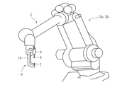
3a 溶接ロボット(作業ロボット)
3b 溶接ロボット(作業ロボット)
4 制御装置
6 溶接ガン(エンドエフェクタ)
TD 搬送方向
W ワーク
WP1 第1の打点(第1の作業位置)
WP2 第2の打点(第2の作業位置)
Claims (1)
- ワークに設定される複数の作業位置に対して作業を行う作業設備において、
前記ワークを所定の搬送方向に搬送する搬送装置と、エンドエフェクタを操作して前記複数の作業位置に対して作業を行う作業ロボットと、前記搬送装置及び前記作業ロボットを制御する制御装置とを備え、
前記ワークにおける前記複数の作業位置は、前記搬送方向の下流側に位置する第1の作業位置と、前記搬送方向の上流側に位置する第2の作業位置とを含み、
前記制御装置は、前記搬送装置による前記ワークの搬送を停止させて前記第1の作業位置に対して前記エンドエフェクタによる作業を行い、前記第1の作業位置に対する作業の終了後に、前記第2の作業位置に対して作業を行うべく、前記作業ロボットにより前記エンドエフェクタを前記第1の作業位置から前記第2の作業位置に向かって移動させつつ、前記搬送装置により前記ワークを前記搬送方向に沿って搬送させることを特徴とする作業設備。
Priority Applications (1)
| Application Number | Priority Date | Filing Date | Title |
|---|---|---|---|
| JP2015128612A JP6508827B2 (ja) | 2015-06-26 | 2015-06-26 | 作業設備 |
Applications Claiming Priority (1)
| Application Number | Priority Date | Filing Date | Title |
|---|---|---|---|
| JP2015128612A JP6508827B2 (ja) | 2015-06-26 | 2015-06-26 | 作業設備 |
Publications (2)
| Publication Number | Publication Date |
|---|---|
| JP2017007075A true JP2017007075A (ja) | 2017-01-12 |
| JP6508827B2 JP6508827B2 (ja) | 2019-05-08 |
Family
ID=57761128
Family Applications (1)
| Application Number | Title | Priority Date | Filing Date |
|---|---|---|---|
| JP2015128612A Expired - Fee Related JP6508827B2 (ja) | 2015-06-26 | 2015-06-26 | 作業設備 |
Country Status (1)
| Country | Link |
|---|---|
| JP (1) | JP6508827B2 (ja) |
Citations (4)
| Publication number | Priority date | Publication date | Assignee | Title |
|---|---|---|---|---|
| JPS5847672A (ja) * | 1981-09-12 | 1983-03-19 | Mazda Motor Corp | 搬送車両のブリ−ダバルブ自動エアブロ−装置 |
| JPH04189487A (ja) * | 1990-11-20 | 1992-07-07 | Tokico Ltd | 工業用ロボット |
| JPH091484A (ja) * | 1995-06-20 | 1997-01-07 | Toyota Motor Corp | 走行軸付きロボットのティーチングプログラム修正方法 |
| JPH1039909A (ja) * | 1996-07-23 | 1998-02-13 | Kawasaki Heavy Ind Ltd | 複数台ロボットの作業計画方法 |
-
2015
- 2015-06-26 JP JP2015128612A patent/JP6508827B2/ja not_active Expired - Fee Related
Patent Citations (4)
| Publication number | Priority date | Publication date | Assignee | Title |
|---|---|---|---|---|
| JPS5847672A (ja) * | 1981-09-12 | 1983-03-19 | Mazda Motor Corp | 搬送車両のブリ−ダバルブ自動エアブロ−装置 |
| JPH04189487A (ja) * | 1990-11-20 | 1992-07-07 | Tokico Ltd | 工業用ロボット |
| JPH091484A (ja) * | 1995-06-20 | 1997-01-07 | Toyota Motor Corp | 走行軸付きロボットのティーチングプログラム修正方法 |
| JPH1039909A (ja) * | 1996-07-23 | 1998-02-13 | Kawasaki Heavy Ind Ltd | 複数台ロボットの作業計画方法 |
Also Published As
| Publication number | Publication date |
|---|---|
| JP6508827B2 (ja) | 2019-05-08 |
Similar Documents
| Publication | Publication Date | Title |
|---|---|---|
| KR102448070B1 (ko) | 밴딩가공장치 | |
| KR101554033B1 (ko) | 차량용 휠 캐리어 브라켓의 탭 가공을 위한 다축 자동 탭핑 장치 | |
| US20140283357A1 (en) | Workpiece assembly system and method for assembling workpiece | |
| KR101309518B1 (ko) | 롤러 헤밍 장치 | |
| KR102037889B1 (ko) | 롤 단조기와 그 롤 단조 방법 | |
| CN104801869A (zh) | 一种汽车轮罩自动化焊接生产线及其生产方法 | |
| JP6063466B2 (ja) | テーパー構造作成 | |
| US20140259613A1 (en) | Workpiece assembling apparatus and workpiece assembling method | |
| CN110062679B (zh) | 用于借助于至少两个可被彼此独立地控制的传送装置以在接合之前调整工件的头端之间和/或尾端之间的偏移来接合工件的方法及设备 | |
| JP5598137B2 (ja) | 車体骨格部材及びその製造法 | |
| JP6508827B2 (ja) | 作業設備 | |
| CN206952068U (zh) | 一种步进梁精锻设备 | |
| US20240238908A1 (en) | Transmission pole manufacturing line and method of manufacturing | |
| KR101761673B1 (ko) | 단조 매니퓰레이터 | |
| JP2013198910A (ja) | 部品の搬送および結合装置 | |
| CN204524573U (zh) | 一种汽车轮罩自动化焊接生产线 | |
| KR100728559B1 (ko) | 단조용 소재의 이송장치 | |
| CN109689307B (zh) | 工件自动输送机 | |
| US9764436B2 (en) | Production line for machining at least one surface component and method for machining the at least one surface component in the production line | |
| KR101602164B1 (ko) | 다방향 단조방식을 이용한 파이프의 가공장치 | |
| JP6057321B2 (ja) | ローラヘム加工装置 | |
| JP2011073068A (ja) | 生産システム | |
| JP2010201462A (ja) | 鍛造方法 | |
| CN104354083B (zh) | 一种去毛刺机及其换位机构 | |
| JP5355262B2 (ja) | ワーク搬送装置及びその方法 |
Legal Events
| Date | Code | Title | Description |
|---|---|---|---|
| A621 | Written request for application examination |
Free format text: JAPANESE INTERMEDIATE CODE: A621 Effective date: 20180516 |
|
| A977 | Report on retrieval |
Free format text: JAPANESE INTERMEDIATE CODE: A971007 Effective date: 20190313 |
|
| TRDD | Decision of grant or rejection written | ||
| A01 | Written decision to grant a patent or to grant a registration (utility model) |
Free format text: JAPANESE INTERMEDIATE CODE: A01 Effective date: 20190401 |
|
| A61 | First payment of annual fees (during grant procedure) |
Free format text: JAPANESE INTERMEDIATE CODE: A61 Effective date: 20190401 |
|
| R150 | Certificate of patent or registration of utility model |
Ref document number: 6508827 Country of ref document: JP Free format text: JAPANESE INTERMEDIATE CODE: R150 |
|
| R250 | Receipt of annual fees |
Free format text: JAPANESE INTERMEDIATE CODE: R250 |
|
| R250 | Receipt of annual fees |
Free format text: JAPANESE INTERMEDIATE CODE: R250 |
|
| R250 | Receipt of annual fees |
Free format text: JAPANESE INTERMEDIATE CODE: R250 |
|
| LAPS | Cancellation because of no payment of annual fees |