JP2017207475A - 粗さ測定センサー、粗さ測定センサーを備えた装置、及びそれらの使用 - Google Patents
粗さ測定センサー、粗さ測定センサーを備えた装置、及びそれらの使用 Download PDFInfo
- Publication number
- JP2017207475A JP2017207475A JP2017075028A JP2017075028A JP2017207475A JP 2017207475 A JP2017207475 A JP 2017207475A JP 2017075028 A JP2017075028 A JP 2017075028A JP 2017075028 A JP2017075028 A JP 2017075028A JP 2017207475 A JP2017207475 A JP 2017207475A
- Authority
- JP
- Japan
- Prior art keywords
- sensor
- skid
- roughness measuring
- roughness
- measuring sensor
- Prior art date
- Legal status (The legal status is an assumption and is not a legal conclusion. Google has not performed a legal analysis and makes no representation as to the accuracy of the status listed.)
- Granted
Links
Images





Classifications
-
- G—PHYSICS
- G01—MEASURING; TESTING
- G01B—MEASURING LENGTH, THICKNESS OR SIMILAR LINEAR DIMENSIONS; MEASURING ANGLES; MEASURING AREAS; MEASURING IRREGULARITIES OF SURFACES OR CONTOURS
- G01B5/00—Measuring arrangements characterised by the use of mechanical techniques
- G01B5/28—Measuring arrangements characterised by the use of mechanical techniques for measuring roughness or irregularity of surfaces
-
- G—PHYSICS
- G01—MEASURING; TESTING
- G01B—MEASURING LENGTH, THICKNESS OR SIMILAR LINEAR DIMENSIONS; MEASURING ANGLES; MEASURING AREAS; MEASURING IRREGULARITIES OF SURFACES OR CONTOURS
- G01B5/00—Measuring arrangements characterised by the use of mechanical techniques
- G01B5/20—Measuring arrangements characterised by the use of mechanical techniques for measuring contours or curvatures
- G01B5/202—Measuring arrangements characterised by the use of mechanical techniques for measuring contours or curvatures of gears
-
- G—PHYSICS
- G01—MEASURING; TESTING
- G01B—MEASURING LENGTH, THICKNESS OR SIMILAR LINEAR DIMENSIONS; MEASURING ANGLES; MEASURING AREAS; MEASURING IRREGULARITIES OF SURFACES OR CONTOURS
- G01B7/00—Measuring arrangements characterised by the use of electric or magnetic techniques
- G01B7/28—Measuring arrangements characterised by the use of electric or magnetic techniques for measuring contours or curvatures
- G01B7/283—Measuring arrangements characterised by the use of electric or magnetic techniques for measuring contours or curvatures of gears
-
- G—PHYSICS
- G01—MEASURING; TESTING
- G01B—MEASURING LENGTH, THICKNESS OR SIMILAR LINEAR DIMENSIONS; MEASURING ANGLES; MEASURING AREAS; MEASURING IRREGULARITIES OF SURFACES OR CONTOURS
- G01B7/00—Measuring arrangements characterised by the use of electric or magnetic techniques
- G01B7/34—Measuring arrangements characterised by the use of electric or magnetic techniques for measuring roughness or irregularity of surfaces
-
- G—PHYSICS
- G01—MEASURING; TESTING
- G01B—MEASURING LENGTH, THICKNESS OR SIMILAR LINEAR DIMENSIONS; MEASURING ANGLES; MEASURING AREAS; MEASURING IRREGULARITIES OF SURFACES OR CONTOURS
- G01B7/00—Measuring arrangements characterised by the use of electric or magnetic techniques
- G01B7/34—Measuring arrangements characterised by the use of electric or magnetic techniques for measuring roughness or irregularity of surfaces
- G01B7/345—Measuring arrangements characterised by the use of electric or magnetic techniques for measuring roughness or irregularity of surfaces for measuring evenness
Landscapes
- Physics & Mathematics (AREA)
- General Physics & Mathematics (AREA)
- A Measuring Device Byusing Mechanical Method (AREA)
- Length Measuring Devices With Unspecified Measuring Means (AREA)
Abstract
Description
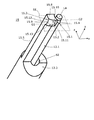
この配置は、特にスキッド15.3とセンサーアーム13.1との間の短距離、及び機械的に頑丈な構成を可能にする。
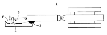
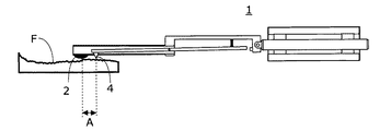
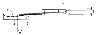
2 スキッド
3 センサー
4 センサー先端
7 歯
8 歯根
10 測定デバイス/装置
11 部品/歯車
12 (粗さ)センサーシステム
12.1 (スプリング)平行四辺形構造
13 ドライバー
13.1 レバーアーム/センサーアーム
13.3 中空円筒
14 センタリング手段
15 (粗さ)測定センサー
15.1 最低接点
15.2 最低摺動点
15.3 スキッド
15.4 センサー先端
15.5 後端
15.6 アダプター板
15.7 板
15.8 端部表面/端面
15.9 底側面
15.10 底の横エッジ
15.11 底の縦エッジ
15.12 外側の底の縦エッジ
15.13 底の横エッジ
19 ハウジング
40 平行四辺形構造
41 対で配置された要素
42 対で配置された要素
43 基準/指示要素
44 定型化した測定トランスデューサー
A 距離
A1 横方向距離
A2 縦方向の距離
A3 横方向距離
A4 縦方向の距離
B1 領域
B2 領域
A1 回転軸
D1 直径
F 表面
G1 直線
G2 直線
LA 前後軸
P1 ポイント
P2 ポイント
P3 矢印
SE 交差面
x、y、z 座標
ω1 回転運動
Claims (11)
- 摺動素子及びセンサー先端(15.4)を備え、ここでセンサー先端(15.4)は、センサーアーム(13.1)の外面端の領域に配置され、センサーアームは、前後軸(LA)と平行な長手方向伸張部分を有してこ状様式にて装着される、粗さ測定センサー(15)であって、
摺動素子は、スキッド(15.3)の形態で形成されており、
スキッド(15.3)は、前後軸(LA)に垂直に位置する交差面(SE)で見た状態において、センサー先端(15.4)の横に隣接して配置されており、
センサー先端(15.4)は、前後軸(LA)に垂直に位置する横断面(SE)で見た状態において、最低接点(15.1)を定義し、スキッド(15.3)は、横断面(SE)で見た状態において、最低摺動点(15.2)を有する湾曲したプログレッション部を有する、
ことを特徴とする粗さ測定センサー。 - センサーアーム(13.1)は、その外面端の領域において円柱、中空円筒、あるいは他のロッド形状要素の形状を有し、センサー先端(15.4)は、ロッド形状要素の外周に配置され、ここでセンサー先端(15.4)は、好ましくは前後軸(LA)に対して半径方向に延在する、請求項1に記載の粗さ測定センサー。
- センサー先端(15.4)は、ロッド形状要素を部分的にあるいは完全に突き抜けている、請求項2に記載の粗さ測定センサー。
- スキッド(15.3)の最低摺動点(15.2)は、スキッド(15.3)の底の縦エッジ(15.11)から横方向距離(A1)を有し、及びスキッド(15.3)の底の横エッジ(15.10)から縦方向距離(A2)を有する、請求項1に記載の粗さ測定センサー。
- スキッド(15.3)は、縦断面で見た状態において凸状で湾曲したプログレッション部を有し、該凸状で湾曲したプログレッション部は、湾曲したプログレッション部の上り勾配がゼロに等しいポイント(P1)を有し、該ポイントは、センサー先端(15.4)の最低接点(15.1)と同じ横断面(SE)に位置する、請求項1から4のいずれかに記載の粗さ測定センサー。
- 少なくとも部分的に中空あるいは開口した形態で形成した領域を備え、センサーアーム(13.1)がレバーの形態で装着されることにより、上記領域の内側にレバーアームベアリングを収容する、請求項1から5のいずれかに記載の粗さ測定センサー。
- 当該粗さ測定センサーは、センサーアーム(13.1)の外面端領域に非対称な構成を有し、非対称構成では、スキッド(15.3)は、センサー先端(15.4)の右あるいは左の横方向に位置する、請求項1から6のいずれかに記載の粗さ測定センサー。
- 当該粗さ測定センサー(15)は、センサーアーム(13.1)の外面端領域に対称な構成を有し、対称構成では、一つのスキッド(15.3)がセンサー先端(15.4)の右の横方向に位置し、一つのスキッド(15.3)がセンサー先端(15.4)の左の横方向に位置する、請求項1から6のいずれかに記載の粗さ測定センサー。
- 粗さセンサーシステム(12)及び請求項1から8のいずれかに記載の粗さ測定センサー(15)を有する装置であって、
粗さセンサーシステム(12)は、歯車(11)の歯面の表面粗さを測定するために構成されている、
ことを特徴とする装置。 - 歯車(11)の歯面の表面粗さを測定する間、歯面に沿った輪郭方向に均一な方法にて粗さ測定センサー(15)を前後軸(LA)に案内することを可能にするため、一つもしくは幾つかのセンサー軸を備える、請求項11に記載の装置。
- 歯車(11)の歯面の表面粗さを測定する請求項1から8のいずれかに記載の粗さ測定センサー(15)の使用であって、
粗さ測定センサー(15)の前後軸(LA)は、歯面に沿った輪郭方向において均一な方法でガイドされ、好ましくは歯根(8)の領域における出発点から歯頭の領域における終点まで引かれるような、
使用。
Applications Claiming Priority (2)
| Application Number | Priority Date | Filing Date | Title |
|---|---|---|---|
| EP16163956.2 | 2016-04-06 | ||
| EP16163956.2A EP3228974B1 (de) | 2016-04-06 | 2016-04-06 | Rauheitsmesstaster, vorrichtung mit rauheitsmesstaster und entsprechende verwendung |
Publications (2)
| Publication Number | Publication Date |
|---|---|
| JP2017207475A true JP2017207475A (ja) | 2017-11-24 |
| JP6976070B2 JP6976070B2 (ja) | 2021-12-01 |
Family
ID=55701770
Family Applications (1)
| Application Number | Title | Priority Date | Filing Date |
|---|---|---|---|
| JP2017075028A Active JP6976070B2 (ja) | 2016-04-06 | 2017-04-05 | 粗さ測定センサー、粗さ測定センサーを備えた装置、及びそれらの使用 |
Country Status (4)
| Country | Link |
|---|---|
| US (1) | US10539407B2 (ja) |
| EP (1) | EP3228974B1 (ja) |
| JP (1) | JP6976070B2 (ja) |
| CN (1) | CN107270805B (ja) |
Families Citing this family (7)
| Publication number | Priority date | Publication date | Assignee | Title |
|---|---|---|---|---|
| DE202017105125U1 (de) * | 2017-08-25 | 2017-09-01 | Klingelnberg Gmbh | Vorrichtung mit Tastsystem und mit berührungslos arbeitendem Sensor |
| EP3569976B1 (de) | 2018-05-16 | 2023-07-05 | Klingelnberg GmbH | Rauheitsmesstaster, vorrichtung mit rauheitsmesstaster und entsprechende verwendung |
| WO2020058840A1 (en) * | 2018-09-17 | 2020-03-26 | Anupam Lavania | A mechanism for aligning and orienting a probe in an optical system |
| DE202019103139U1 (de) | 2019-06-04 | 2019-06-21 | Klingelnberg Gmbh | Messvorrichtung zum Abtasten einer Oberfläche eines Bauteils und Koordinatenmesssystem mit einer solchen Messvorrichtung |
| CN112361940A (zh) * | 2020-12-01 | 2021-02-12 | 中建八局科技建设有限公司 | 平整度测量尺及测量方法 |
| WO2026012529A1 (de) | 2024-07-09 | 2026-01-15 | Klingelnberg Gmbh | Hybrider rauheitstaster |
| CN119559229B (zh) * | 2025-01-24 | 2025-03-28 | 西安威而信精密仪器有限公司 | 一种基于机器视觉的磨齿齿面粗糙度测量方法 |
Citations (7)
| Publication number | Priority date | Publication date | Assignee | Title |
|---|---|---|---|---|
| JPS6367912U (ja) * | 1986-10-23 | 1988-05-07 | ||
| JPH02150503U (ja) * | 1989-05-25 | 1990-12-26 | ||
| JPH06213656A (ja) * | 1993-01-18 | 1994-08-05 | Mitsutoyo Corp | 表面粗さ測定装置 |
| US6000282A (en) * | 1998-02-17 | 1999-12-14 | Seagate Technology, Inc. | System and method for uniform frequency response independent of slider contact location in glide tests |
| JP2009503461A (ja) * | 2005-07-27 | 2009-01-29 | カール マール ホールディング ゲーエムベーハー | 粗度走査装置 |
| JP2010117196A (ja) * | 2008-11-12 | 2010-05-27 | Mitsubishi Heavy Ind Ltd | 歯車測定方法 |
| DE102014110801A1 (de) * | 2014-07-30 | 2016-02-04 | Hexagon Metrology Gmbh | Verfahren zur Ausrichtung eines an einem Koordinatenmessgerät angeordneten Rauheitssensors sowie Koordinatenmessgerät zur Durchführung des Verfahrens |
Family Cites Families (17)
| Publication number | Priority date | Publication date | Assignee | Title |
|---|---|---|---|---|
| DE2535912A1 (de) * | 1975-08-12 | 1977-02-17 | Salje Ernst | Verfahren und vorrichtung zur rauhigkeitspruefung von oberflaechen |
| US4712208A (en) * | 1977-12-12 | 1987-12-08 | Dolby Ray Milton | Disc reproducing system for compensating mechanical imperfections |
| US4776212A (en) * | 1987-06-19 | 1988-10-11 | Federal Products Corporation | Pocket surface roughness gage |
| JPH0820247B2 (ja) * | 1988-11-09 | 1996-03-04 | 株式会社ミツトヨ | 表面粗さ計のノーズピース |
| US5136527A (en) * | 1990-10-05 | 1992-08-04 | Precision Devices, Inc. | Surface finish measuring device and method for gear teeth |
| US6397667B1 (en) * | 1997-12-26 | 2002-06-04 | Mitutoyo Corporation | Surface property measuring device |
| JP3443054B2 (ja) * | 1999-11-01 | 2003-09-02 | 株式会社ミツトヨ | 表面性状測定機用検出器 |
| ATE378571T1 (de) | 2004-04-23 | 2007-11-15 | Klingelnberg Gmbh | Vorrichtung mit abnehmbarem messtaster und messgerät mit einer solchen vorrichtung |
| DE102005007002B4 (de) * | 2005-02-16 | 2006-12-28 | Carl Mahr Holding Gmbh | Rauheitsmessgerät mit wechselbarem Tastarm |
| US20110027754A1 (en) * | 2005-03-31 | 2011-02-03 | Richard Golden | Dental pliers with adjustable bumper |
| CN101458058B (zh) * | 2007-12-12 | 2010-09-29 | 鸿富锦精密工业(深圳)有限公司 | 量测装置 |
| EP2199732B1 (de) | 2008-12-19 | 2017-10-11 | Klingelnberg AG | Vorrichtung mit Rauheitsmesstaster |
| JP6104557B2 (ja) * | 2012-10-18 | 2017-03-29 | 株式会社ミツトヨ | 表面粗さ測定ユニット、三次元測定装置 |
| CN202885760U (zh) * | 2012-10-29 | 2013-04-17 | 苏州市中瑞模具有限公司 | 变形检测治具 |
| DE202013102048U1 (de) * | 2013-05-10 | 2013-05-21 | Breitmeier Messtechnik Gmbh | Oberflächenmikrostrukturmessgerät mit Hilfs-Abstandsmeßsystem |
| DE202013102044U1 (de) * | 2013-05-10 | 2013-05-21 | Breitmeier Messtechnik Gmbh | Oberflächenmikrostrukturmessgerät mit Bilderfassung |
| JP5846462B1 (ja) * | 2014-10-28 | 2016-01-20 | 株式会社東京精密 | 形状測定装置 |
-
2016
- 2016-04-06 EP EP16163956.2A patent/EP3228974B1/de active Active
-
2017
- 2017-04-05 JP JP2017075028A patent/JP6976070B2/ja active Active
- 2017-04-05 US US15/479,963 patent/US10539407B2/en active Active
- 2017-04-06 CN CN201710219948.XA patent/CN107270805B/zh active Active
Patent Citations (7)
| Publication number | Priority date | Publication date | Assignee | Title |
|---|---|---|---|---|
| JPS6367912U (ja) * | 1986-10-23 | 1988-05-07 | ||
| JPH02150503U (ja) * | 1989-05-25 | 1990-12-26 | ||
| JPH06213656A (ja) * | 1993-01-18 | 1994-08-05 | Mitsutoyo Corp | 表面粗さ測定装置 |
| US6000282A (en) * | 1998-02-17 | 1999-12-14 | Seagate Technology, Inc. | System and method for uniform frequency response independent of slider contact location in glide tests |
| JP2009503461A (ja) * | 2005-07-27 | 2009-01-29 | カール マール ホールディング ゲーエムベーハー | 粗度走査装置 |
| JP2010117196A (ja) * | 2008-11-12 | 2010-05-27 | Mitsubishi Heavy Ind Ltd | 歯車測定方法 |
| DE102014110801A1 (de) * | 2014-07-30 | 2016-02-04 | Hexagon Metrology Gmbh | Verfahren zur Ausrichtung eines an einem Koordinatenmessgerät angeordneten Rauheitssensors sowie Koordinatenmessgerät zur Durchführung des Verfahrens |
Also Published As
| Publication number | Publication date |
|---|---|
| JP6976070B2 (ja) | 2021-12-01 |
| US20170292823A1 (en) | 2017-10-12 |
| US10539407B2 (en) | 2020-01-21 |
| CN107270805A (zh) | 2017-10-20 |
| CN107270805B (zh) | 2021-04-09 |
| EP3228974A1 (de) | 2017-10-11 |
| EP3228974B1 (de) | 2022-06-01 |
Similar Documents
| Publication | Publication Date | Title |
|---|---|---|
| JP6976070B2 (ja) | 粗さ測定センサー、粗さ測定センサーを備えた装置、及びそれらの使用 | |
| CN102405393B (zh) | 具有粗糙度测量传感器的装置和相应方法 | |
| EP2631592B1 (de) | Messgerät und Verfahren zur Messung der Rauheit einer Oberfläche eines Körpers | |
| EP1975557B1 (en) | Apparatus, method and program for measuring surface texture | |
| JP2016536603A (ja) | 工作機械内で使用するための粗さ測定機器及び工作機械内で粗さ測定する方法 | |
| CN101745845B (zh) | 一种金属零件外轮廓形状的测量方法及加工精度的检测方法 | |
| JP6310156B2 (ja) | 粗さセンサの測定条件を決定するための方法、ワーク表面の粗さを測定するための方法、コンピュータプログラム製品、及び方法を実行するように設計された測定装置 | |
| JPH08261748A (ja) | 粗さ測定用の装置を備えた座標測定装置 | |
| JP2017181135A (ja) | 走査型プローブ顕微鏡及びそのプローブ接触検出方法 | |
| CN107532892A (zh) | 用于检测粗糙度传感器的动态振动的方法、用于测量工件表面的粗糙度的方法、计算机程序产品以及用于实施方法的测量设备 | |
| JP2007248463A (ja) | ワイヤ取付具の幾何学的データを決定するための方法および装置 | |
| CN110500971B (zh) | 粗糙度测量探针,具有粗糙度测量探针的装置以及相对应的使用 | |
| US20190029505A1 (en) | Optical interference tomographic image generating apparatus and method for using same | |
| DE102009019129A1 (de) | Vorrichtung zur Positionierung eines Sensors | |
| KR102401245B1 (ko) | 기어 휠 워크피스의 이뿌리면 상의 접촉 측정 | |
| CN101520321B (zh) | 精度检测设备 | |
| DE202014101900U1 (de) | Manipulator zur räumlichen Orientierung eines Miniatur-Rauheitsmessgeräts | |
| EP2817584B9 (de) | Kugel-schaft-verbindung | |
| Chen et al. | Dynamic reflection behaviors of weld pool surface in pulsed GTAW | |
| JP2010190797A (ja) | 開先部最深位置検出装置および開先部最深位置検出方法 | |
| CN213021532U (zh) | 电容器凸顶检测装置 | |
| JP4149424B2 (ja) | ワーク罫書き装置 | |
| DE19504126A1 (de) | Vorrichtung und Verfahren zum berührungslosen Vermessen dreidimensionaler Objekte auf der Basis optischer Triangulation | |
| CN203881472U (zh) | 接触压力及摩擦力动态检测装置 | |
| JP2005161385A (ja) | 水中溶接装置および水中溶接方法 |
Legal Events
| Date | Code | Title | Description |
|---|---|---|---|
| A621 | Written request for application examination |
Free format text: JAPANESE INTERMEDIATE CODE: A621 Effective date: 20200221 |
|
| A977 | Report on retrieval |
Free format text: JAPANESE INTERMEDIATE CODE: A971007 Effective date: 20201222 |
|
| A131 | Notification of reasons for refusal |
Free format text: JAPANESE INTERMEDIATE CODE: A131 Effective date: 20210112 |
|
| A601 | Written request for extension of time |
Free format text: JAPANESE INTERMEDIATE CODE: A601 Effective date: 20210409 |
|
| A521 | Request for written amendment filed |
Free format text: JAPANESE INTERMEDIATE CODE: A523 Effective date: 20210420 |
|
| TRDD | Decision of grant or rejection written | ||
| A01 | Written decision to grant a patent or to grant a registration (utility model) |
Free format text: JAPANESE INTERMEDIATE CODE: A01 Effective date: 20211012 |
|
| A61 | First payment of annual fees (during grant procedure) |
Free format text: JAPANESE INTERMEDIATE CODE: A61 Effective date: 20211109 |
|
| R150 | Certificate of patent or registration of utility model |
Ref document number: 6976070 Country of ref document: JP Free format text: JAPANESE INTERMEDIATE CODE: R150 |
|
| R250 | Receipt of annual fees |
Free format text: JAPANESE INTERMEDIATE CODE: R250 |
|
| R250 | Receipt of annual fees |
Free format text: JAPANESE INTERMEDIATE CODE: R250 |