JP2019100231A - エンジンシステム及び可変圧縮装置の制御方法 - Google Patents
エンジンシステム及び可変圧縮装置の制御方法 Download PDFInfo
- Publication number
- JP2019100231A JP2019100231A JP2017230697A JP2017230697A JP2019100231A JP 2019100231 A JP2019100231 A JP 2019100231A JP 2017230697 A JP2017230697 A JP 2017230697A JP 2017230697 A JP2017230697 A JP 2017230697A JP 2019100231 A JP2019100231 A JP 2019100231A
- Authority
- JP
- Japan
- Prior art keywords
- piston rod
- piston
- engine system
- working fluid
- compression ratio
- Prior art date
- Legal status (The legal status is an assumption and is not a legal conclusion. Google has not performed a legal analysis and makes no representation as to the accuracy of the status listed.)
- Pending
Links
Images



Classifications
-
- F—MECHANICAL ENGINEERING; LIGHTING; HEATING; WEAPONS; BLASTING
- F02—COMBUSTION ENGINES; HOT-GAS OR COMBUSTION-PRODUCT ENGINE PLANTS
- F02B—INTERNAL-COMBUSTION PISTON ENGINES; COMBUSTION ENGINES IN GENERAL
- F02B75/00—Other engines
- F02B75/04—Engines with variable distances between pistons at top dead-centre positions and cylinder heads
- F02B75/045—Engines with variable distances between pistons at top dead-centre positions and cylinder heads by means of a variable connecting rod length
-
- F—MECHANICAL ENGINEERING; LIGHTING; HEATING; WEAPONS; BLASTING
- F01—MACHINES OR ENGINES IN GENERAL; ENGINE PLANTS IN GENERAL; STEAM ENGINES
- F01B—MACHINES OR ENGINES, IN GENERAL OR OF POSITIVE-DISPLACEMENT TYPE, e.g. STEAM ENGINES
- F01B31/00—Component parts, details or accessories not provided for in, or of interest apart from, other groups
- F01B31/14—Changing of compression ratio
-
- F—MECHANICAL ENGINEERING; LIGHTING; HEATING; WEAPONS; BLASTING
- F02—COMBUSTION ENGINES; HOT-GAS OR COMBUSTION-PRODUCT ENGINE PLANTS
- F02B—INTERNAL-COMBUSTION PISTON ENGINES; COMBUSTION ENGINES IN GENERAL
- F02B25/00—Engines characterised by using fresh charge for scavenging cylinders
- F02B25/02—Engines characterised by using fresh charge for scavenging cylinders using unidirectional scavenging
- F02B25/04—Engines having ports both in cylinder head and in cylinder wall near bottom of piston stroke
-
- F—MECHANICAL ENGINEERING; LIGHTING; HEATING; WEAPONS; BLASTING
- F02—COMBUSTION ENGINES; HOT-GAS OR COMBUSTION-PRODUCT ENGINE PLANTS
- F02B—INTERNAL-COMBUSTION PISTON ENGINES; COMBUSTION ENGINES IN GENERAL
- F02B75/00—Other engines
- F02B75/04—Engines with variable distances between pistons at top dead-centre positions and cylinder heads
-
- F—MECHANICAL ENGINEERING; LIGHTING; HEATING; WEAPONS; BLASTING
- F02—COMBUSTION ENGINES; HOT-GAS OR COMBUSTION-PRODUCT ENGINE PLANTS
- F02B—INTERNAL-COMBUSTION PISTON ENGINES; COMBUSTION ENGINES IN GENERAL
- F02B75/00—Other engines
- F02B75/32—Engines characterised by connections between pistons and main shafts and not specific to preceding main groups
-
- F—MECHANICAL ENGINEERING; LIGHTING; HEATING; WEAPONS; BLASTING
- F02—COMBUSTION ENGINES; HOT-GAS OR COMBUSTION-PRODUCT ENGINE PLANTS
- F02D—CONTROLLING COMBUSTION ENGINES
- F02D15/00—Varying compression ratio
- F02D15/02—Varying compression ratio by alteration or displacement of piston stroke
-
- F—MECHANICAL ENGINEERING; LIGHTING; HEATING; WEAPONS; BLASTING
- F16—ENGINEERING ELEMENTS AND UNITS; GENERAL MEASURES FOR PRODUCING AND MAINTAINING EFFECTIVE FUNCTIONING OF MACHINES OR INSTALLATIONS; THERMAL INSULATION IN GENERAL
- F16C—SHAFTS; FLEXIBLE SHAFTS; ELEMENTS OR CRANKSHAFT MECHANISMS; ROTARY BODIES OTHER THAN GEARING ELEMENTS; BEARINGS
- F16C7/00—Connecting-rods or like links pivoted at both ends; Construction of connecting-rod heads
- F16C7/06—Adjustable connecting-rods
-
- F—MECHANICAL ENGINEERING; LIGHTING; HEATING; WEAPONS; BLASTING
- F02—COMBUSTION ENGINES; HOT-GAS OR COMBUSTION-PRODUCT ENGINE PLANTS
- F02D—CONTROLLING COMBUSTION ENGINES
- F02D19/00—Controlling engines characterised by their use of non-liquid fuels, pluralities of fuels, or non-fuel substances added to the combustible mixtures
- F02D19/06—Controlling engines characterised by their use of non-liquid fuels, pluralities of fuels, or non-fuel substances added to the combustible mixtures peculiar to engines working with pluralities of fuels, e.g. alternatively with light and heavy fuel oil, other than engines indifferent to the fuel consumed
- F02D19/08—Controlling engines characterised by their use of non-liquid fuels, pluralities of fuels, or non-fuel substances added to the combustible mixtures peculiar to engines working with pluralities of fuels, e.g. alternatively with light and heavy fuel oil, other than engines indifferent to the fuel consumed simultaneously using pluralities of fuels
- F02D19/10—Controlling engines characterised by their use of non-liquid fuels, pluralities of fuels, or non-fuel substances added to the combustible mixtures peculiar to engines working with pluralities of fuels, e.g. alternatively with light and heavy fuel oil, other than engines indifferent to the fuel consumed simultaneously using pluralities of fuels peculiar to compression-ignition engines in which the main fuel is gaseous
-
- Y—GENERAL TAGGING OF NEW TECHNOLOGICAL DEVELOPMENTS; GENERAL TAGGING OF CROSS-SECTIONAL TECHNOLOGIES SPANNING OVER SEVERAL SECTIONS OF THE IPC; TECHNICAL SUBJECTS COVERED BY FORMER USPC CROSS-REFERENCE ART COLLECTIONS [XRACs] AND DIGESTS
- Y02—TECHNOLOGIES OR APPLICATIONS FOR MITIGATION OR ADAPTATION AGAINST CLIMATE CHANGE
- Y02T—CLIMATE CHANGE MITIGATION TECHNOLOGIES RELATED TO TRANSPORTATION
- Y02T10/00—Road transport of goods or passengers
- Y02T10/10—Internal combustion engine [ICE] based vehicles
- Y02T10/30—Use of alternative fuels, e.g. biofuels
Landscapes
- Engineering & Computer Science (AREA)
- General Engineering & Computer Science (AREA)
- Mechanical Engineering (AREA)
- Chemical & Material Sciences (AREA)
- Combustion & Propulsion (AREA)
- Output Control And Ontrol Of Special Type Engine (AREA)
- Shafts, Cranks, Connecting Bars, And Related Bearings (AREA)
Abstract
Description
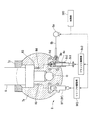
本実施形態のエンジンシステム100は、例えば大型タンカなど船舶に搭載され、図1に示すように、エンジン1と、過給機200と、制御部300(制御手段)と、位置検出部400(図5参照、検出手段)とを有している。なお、本実施形態においては、過給機200を補機として捉え、エンジン1(主機)と別体として説明する。但し、過給機200をエンジン1の一部として構成することも可能である。
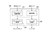
まず、制御部300は、温度取得部320により、温度センサからの入力に基づいて、作動油温度を算出する(ステップS1)。そして、制御部300は、温度取得部320により、算出した作動油温度が閾値以上であるかを判断する(ステップS2)。温度取得部320が作動油温度が閾値以上であると判断した場合、すなわち、ステップS2の判断がYESの場合、制御部300は、プランジャポンプ制御部330及びリリーフ弁制御部3により、それぞれプランジャポンプ8c及びリリーフ弁8fの駆動時間を算出し、プランジャポンプ8c及びリリーフ弁8cを駆動させる(ステップS3)。これにより、油圧室R3においては、内部の作動油が排出されると共に新たな作動油が供給され、油圧室R4内部の作動油の温度が低下する。
ピストン4が下死点に位置するときの筒内圧をP0、ピストン4が上死点に位置するときの筒内圧をP1としたとき、圧縮比εは、下記式1で示される。なおκは、ポリトロープ指数を示す。

上記第1実施形態の変形例を第2実施形態として説明する。なお、上記第1実施形態と同一の構成の部材については、同一の符号を付し、説明を省略する。
本実施形態においては、ピストンロッド位置取得部310は、位置検出部400からの入力に基づいて、ピストンロッド6の位置を算出する。
本実施形態におけるエンジンシステム100は、位置検出部400の代わりに、位置検出部500(検出手段)を有している。位置検出部500は、図6に示すように、センサ部510と、被検出部520とを有している。センサ部510は、掃気ポートSよりも燃焼室R1から離れた位置であるシリンダライナ3aの内周面下端側に埋設されて固定されている。センサ部510は、2つの被検出部520の移動に伴う被検出部520の表面との距離の変化により電気信号(ピストンロッド6の位置情報を含む信号)を発生させるセンサである。
本実施形態においては、ピストンロッド位置取得部310は、位置検出部500からの入力に基づいて、ピストンロッド6の位置を算出する。
2 架構
3 シリンダ部
3a シリンダライナ
3b シリンダヘッド
3c シリンダジャケット
4 ピストン
5 排気弁ユニット
5 ピストン
5a 排気弁
5b 排気弁筐
5c 排気弁駆動部
6 直接ピストンロッド
6 ピストンロッド
7 クロスヘッド
7a クロスヘッドピン
7b ガイドシュー
7c 蓋部材
8 油圧部
8a 供給ポンプ
8b 揺動管
8c プランジャポンプ
8c1 プランジャ
8c2 シリンダ
8c3 プランジャ駆動部
8d 第1逆止弁
8e 第2逆止弁
8f リリーフ弁
8f1 本体部
8f2 リリーフ弁駆動部
9 連接棒
10 クランク角センサ
11 クランク軸
12 掃気溜
13 排気溜
14 空気冷却器
100 エンジンシステム
200 過給機
300 制御部
310 ピストンロッド位置取得部
400 位置検出部
410 磁気センサ
411 凹凸部
412 凹凸部
420 ロッド部
421 ロッド
422 保持部
423 付勢バネ
424 磁性部材
430 通信部
500 位置検出部
510 センサ部
520 被検出部
H 排気ポート
O 出口孔
R1 燃焼室
R2 掃気室
R3 油圧室
R4 供給流路
R5 リリーフ流路
R6 補助流路
S 掃気ポート
Claims (5)
- 昇圧された作動流体が供給されることで、ピストンと接続されるピストンロッドが圧縮比を高める方向に移動される流体室を有する可変圧縮装置を備えるエンジンシステムであって、
前記作動流体を昇圧して前記流体室に供給する昇圧機構と、
前記ピストンロッドの位置情報を含む信号を出力する検出手段と、
前記位置情報に基づいて前記ピストンロッドの移動位置を保持するように前記昇圧機構を制御する制御手段と
を有することを特徴とするエンジンシステム。 - 前記検出手段は、前記シリンダライナに設けられると共に前記ピストンの位置情報を含む信号を出力することを特徴とする請求項1に記載のエンジンシステム。
- 前記検出手段は、ピストンロッドに固定された被検出部の移動を非接触で検出するセンサ部を有することを特徴とする請求項1に記載のエンジンシステム。
- 前記流体室と外部とを連通する流路に排出弁を有し、
前記制御手段は、前記昇圧機構と前記排出弁とを制御して前記作動流体を供給しつつ排出させることを特徴とする請求項1〜3のいずれか一項に記載のエンジンシステム。 - 昇圧された作動流体が供給されることで、ピストンと接続されるピストンロッドが圧縮比を高める方向に移動される流体室を有する可変圧縮装置の制御方法であって、
前記ピストンロッドの位置情報に基づいて、前記ピストンロッドの移動位置を保持するように、前記作動流体を昇圧して前記流体室に供給または前記作動流体を前記流体室から排出する昇圧機構を制御することを特徴とする可変圧縮装置の制御方法。
Priority Applications (6)
| Application Number | Priority Date | Filing Date | Title |
|---|---|---|---|
| JP2017230697A JP2019100231A (ja) | 2017-11-30 | 2017-11-30 | エンジンシステム及び可変圧縮装置の制御方法 |
| CN201880077857.XA CN111386391A (zh) | 2017-11-30 | 2018-11-30 | 发动机系统和可变压缩装置的控制方法 |
| KR1020207009651A KR102383382B1 (ko) | 2017-11-30 | 2018-11-30 | 엔진 시스템 및 가변 압축 장치의 제어 방법 |
| PCT/JP2018/044210 WO2019107549A1 (ja) | 2017-11-30 | 2018-11-30 | エンジンシステム及び可変圧縮装置の制御方法 |
| EP18882828.9A EP3719286A4 (en) | 2017-11-30 | 2018-11-30 | ENGINE SYSTEM AND METHOD OF CONTROLLING A VARIABLE COMPRESSION DEVICE |
| JP2022146034A JP2022171794A (ja) | 2017-11-30 | 2022-09-14 | エンジンシステム及び可変圧縮装置の制御方法 |
Applications Claiming Priority (1)
| Application Number | Priority Date | Filing Date | Title |
|---|---|---|---|
| JP2017230697A JP2019100231A (ja) | 2017-11-30 | 2017-11-30 | エンジンシステム及び可変圧縮装置の制御方法 |
Related Child Applications (1)
| Application Number | Title | Priority Date | Filing Date |
|---|---|---|---|
| JP2022146034A Division JP2022171794A (ja) | 2017-11-30 | 2022-09-14 | エンジンシステム及び可変圧縮装置の制御方法 |
Publications (1)
| Publication Number | Publication Date |
|---|---|
| JP2019100231A true JP2019100231A (ja) | 2019-06-24 |
Family
ID=66663972
Family Applications (2)
| Application Number | Title | Priority Date | Filing Date |
|---|---|---|---|
| JP2017230697A Pending JP2019100231A (ja) | 2017-11-30 | 2017-11-30 | エンジンシステム及び可変圧縮装置の制御方法 |
| JP2022146034A Pending JP2022171794A (ja) | 2017-11-30 | 2022-09-14 | エンジンシステム及び可変圧縮装置の制御方法 |
Family Applications After (1)
| Application Number | Title | Priority Date | Filing Date |
|---|---|---|---|
| JP2022146034A Pending JP2022171794A (ja) | 2017-11-30 | 2022-09-14 | エンジンシステム及び可変圧縮装置の制御方法 |
Country Status (5)
| Country | Link |
|---|---|
| EP (1) | EP3719286A4 (ja) |
| JP (2) | JP2019100231A (ja) |
| KR (1) | KR102383382B1 (ja) |
| CN (1) | CN111386391A (ja) |
| WO (1) | WO2019107549A1 (ja) |
Citations (3)
| Publication number | Priority date | Publication date | Assignee | Title |
|---|---|---|---|---|
| JP2000337305A (ja) * | 1999-05-17 | 2000-12-05 | Caterpillar Inc | 油圧シリンダの作動制御装置および方法 |
| JP2003130008A (ja) * | 2001-10-26 | 2003-05-08 | Smc Corp | 加圧シリンダの高速駆動方法及びその装置 |
| WO2015108182A1 (ja) * | 2014-01-20 | 2015-07-23 | 株式会社Ihi | エンジン |
Family Cites Families (12)
| Publication number | Priority date | Publication date | Assignee | Title |
|---|---|---|---|---|
| JPS59164406A (ja) * | 1983-03-03 | 1984-09-17 | Taiyo Tekko Kk | ストローク位置検出用ピストンロッドの製造方法 |
| JPS61283802A (ja) * | 1985-06-10 | 1986-12-13 | Toshiba Mach Co Ltd | ダイカストマシンにおける絶対位置検出装置 |
| JPS63164535U (ja) * | 1987-04-16 | 1988-10-26 | ||
| US7827943B2 (en) * | 2008-02-19 | 2010-11-09 | Tonand Brakes Inc | Variable compression ratio system |
| JP5120214B2 (ja) * | 2008-11-07 | 2013-01-16 | いすゞ自動車株式会社 | 内燃機関の可変圧縮比機構 |
| JP5169881B2 (ja) * | 2009-01-30 | 2013-03-27 | 日産自動車株式会社 | 内燃機関の可変圧縮比装置 |
| JP2011202621A (ja) * | 2010-03-26 | 2011-10-13 | Honda Motor Co Ltd | 内燃機関の制御装置 |
| JP2013256886A (ja) * | 2012-06-12 | 2013-12-26 | Toyota Central R&D Labs Inc | フリーピストン式発電機 |
| CN103541819B (zh) | 2012-07-17 | 2017-08-08 | 瓦锡兰瑞士公司 | 大型往复活塞式燃烧发动机及其控制设备和控制方法 |
| JP2015021433A (ja) * | 2013-07-19 | 2015-02-02 | 三菱自動車工業株式会社 | 可変圧縮比エンジンの制御装置 |
| KR101534709B1 (ko) * | 2013-12-18 | 2015-07-08 | 현대자동차 주식회사 | 가변 압축비 엔진 |
| JP6137341B2 (ja) * | 2014-01-20 | 2017-05-31 | 株式会社Ihi | クロスヘッド型エンジン |
-
2017
- 2017-11-30 JP JP2017230697A patent/JP2019100231A/ja active Pending
-
2018
- 2018-11-30 EP EP18882828.9A patent/EP3719286A4/en active Pending
- 2018-11-30 KR KR1020207009651A patent/KR102383382B1/ko active Active
- 2018-11-30 CN CN201880077857.XA patent/CN111386391A/zh active Pending
- 2018-11-30 WO PCT/JP2018/044210 patent/WO2019107549A1/ja not_active Ceased
-
2022
- 2022-09-14 JP JP2022146034A patent/JP2022171794A/ja active Pending
Patent Citations (3)
| Publication number | Priority date | Publication date | Assignee | Title |
|---|---|---|---|---|
| JP2000337305A (ja) * | 1999-05-17 | 2000-12-05 | Caterpillar Inc | 油圧シリンダの作動制御装置および方法 |
| JP2003130008A (ja) * | 2001-10-26 | 2003-05-08 | Smc Corp | 加圧シリンダの高速駆動方法及びその装置 |
| WO2015108182A1 (ja) * | 2014-01-20 | 2015-07-23 | 株式会社Ihi | エンジン |
Also Published As
| Publication number | Publication date |
|---|---|
| JP2022171794A (ja) | 2022-11-11 |
| EP3719286A1 (en) | 2020-10-07 |
| KR102383382B1 (ko) | 2022-04-08 |
| WO2019107549A1 (ja) | 2019-06-06 |
| KR20200042005A (ko) | 2020-04-22 |
| EP3719286A4 (en) | 2021-08-25 |
| CN111386391A (zh) | 2020-07-07 |
Similar Documents
| Publication | Publication Date | Title |
|---|---|---|
| US10087831B2 (en) | Engine | |
| KR102240874B1 (ko) | 가변 압축 장치 및 엔진 시스템 | |
| KR102371032B1 (ko) | 압축단 압력 제어 장치 및 엔진 시스템 | |
| KR102502627B1 (ko) | 엔진 시스템 | |
| KR102383655B1 (ko) | 엔진 시스템 | |
| JP2022171794A (ja) | エンジンシステム及び可変圧縮装置の制御方法 | |
| JP6946977B2 (ja) | 可変圧縮装置及びエンジンシステム | |
| KR102274364B1 (ko) | 가변 압축 장치 및 엔진 시스템 | |
| JP2019120165A (ja) | 可変圧縮装置及びエンジンシステム | |
| EP3674528B1 (en) | Variable compression device and engine system | |
| JP2019120237A (ja) | 圧縮比制御装置及びエンジンシステム | |
| JP2019019801A (ja) | 可変圧縮装置及びエンジンシステム |
Legal Events
| Date | Code | Title | Description |
|---|---|---|---|
| A621 | Written request for application examination |
Free format text: JAPANESE INTERMEDIATE CODE: A621 Effective date: 20200716 |
|
| A131 | Notification of reasons for refusal |
Free format text: JAPANESE INTERMEDIATE CODE: A131 Effective date: 20211102 |
|
| A521 | Request for written amendment filed |
Free format text: JAPANESE INTERMEDIATE CODE: A523 Effective date: 20211215 |
|
| A131 | Notification of reasons for refusal |
Free format text: JAPANESE INTERMEDIATE CODE: A131 Effective date: 20220325 |
|
| A521 | Request for written amendment filed |
Free format text: JAPANESE INTERMEDIATE CODE: A523 Effective date: 20220524 |
|
| A02 | Decision of refusal |
Free format text: JAPANESE INTERMEDIATE CODE: A02 Effective date: 20220614 |