JP2022013376A - 熱電発電モジュール - Google Patents
熱電発電モジュール Download PDFInfo
- Publication number
- JP2022013376A JP2022013376A JP2020115893A JP2020115893A JP2022013376A JP 2022013376 A JP2022013376 A JP 2022013376A JP 2020115893 A JP2020115893 A JP 2020115893A JP 2020115893 A JP2020115893 A JP 2020115893A JP 2022013376 A JP2022013376 A JP 2022013376A
- Authority
- JP
- Japan
- Prior art keywords
- substrate
- generation module
- power generation
- metal layer
- hole
- Prior art date
- Legal status (The legal status is an assumption and is not a legal conclusion. Google has not performed a legal analysis and makes no representation as to the accuracy of the status listed.)
- Granted
Links
Images




Classifications
-
- H—ELECTRICITY
- H10—SEMICONDUCTOR DEVICES; ELECTRIC SOLID-STATE DEVICES NOT OTHERWISE PROVIDED FOR
- H10N—ELECTRIC SOLID-STATE DEVICES NOT OTHERWISE PROVIDED FOR
- H10N10/00—Thermoelectric devices comprising a junction of dissimilar materials, i.e. devices exhibiting Seebeck or Peltier effects
- H10N10/80—Constructional details
- H10N10/82—Interconnections
-
- H—ELECTRICITY
- H10—SEMICONDUCTOR DEVICES; ELECTRIC SOLID-STATE DEVICES NOT OTHERWISE PROVIDED FOR
- H10N—ELECTRIC SOLID-STATE DEVICES NOT OTHERWISE PROVIDED FOR
- H10N10/00—Thermoelectric devices comprising a junction of dissimilar materials, i.e. devices exhibiting Seebeck or Peltier effects
- H10N10/01—Manufacture or treatment
-
- H—ELECTRICITY
- H10—SEMICONDUCTOR DEVICES; ELECTRIC SOLID-STATE DEVICES NOT OTHERWISE PROVIDED FOR
- H10N—ELECTRIC SOLID-STATE DEVICES NOT OTHERWISE PROVIDED FOR
- H10N10/00—Thermoelectric devices comprising a junction of dissimilar materials, i.e. devices exhibiting Seebeck or Peltier effects
- H10N10/10—Thermoelectric devices comprising a junction of dissimilar materials, i.e. devices exhibiting Seebeck or Peltier effects operating with only the Peltier or Seebeck effects
- H10N10/17—Thermoelectric devices comprising a junction of dissimilar materials, i.e. devices exhibiting Seebeck or Peltier effects operating with only the Peltier or Seebeck effects characterised by the structure or configuration of the cell or thermocouple forming the device
-
- H—ELECTRICITY
- H10—SEMICONDUCTOR DEVICES; ELECTRIC SOLID-STATE DEVICES NOT OTHERWISE PROVIDED FOR
- H10N—ELECTRIC SOLID-STATE DEVICES NOT OTHERWISE PROVIDED FOR
- H10N10/00—Thermoelectric devices comprising a junction of dissimilar materials, i.e. devices exhibiting Seebeck or Peltier effects
- H10N10/80—Constructional details
- H10N10/85—Thermoelectric active materials
- H10N10/851—Thermoelectric active materials comprising inorganic compositions
- H10N10/854—Thermoelectric active materials comprising inorganic compositions comprising only metals
Landscapes
- Engineering & Computer Science (AREA)
- Manufacturing & Machinery (AREA)
- Chemical & Material Sciences (AREA)
- Inorganic Chemistry (AREA)
- Cooling Or The Like Of Semiconductors Or Solid State Devices (AREA)
Abstract
Description
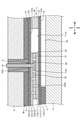
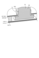
図1は、実施形態に係る熱電発電モジュールを示す断面図である。熱電発電モジュール1は、熱源側の高温側プレート2と、冷却側の低温側プレート4とで挟まれる。熱電発電モジュール1は、高温側プレート2と低温側プレート4とによって両側(図中の上下)に温度差を与えることによって、ゼーベック効果により発電する。
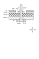
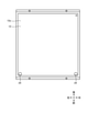
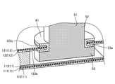
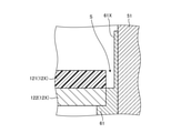
次に、半田61による、ターミナルピン51と貫通孔24との封止方法及び作用について説明する。貫通孔24へ下側からターミナルピン51を通し、第2電極23とターミナルピン51を半田61によって半田接合する。より詳しくは、貫通孔24に挿通されたターミナルピン51の頭部53の上面53aを第2電極23に接触させる。ターミナルピン51の頭部53の上面53aには半田61が塗布されている。この状態で焼成処理して、第2電極23とターミナルピン51を半田接合する。熱電変換素子21を半田接合している第2基板12の上面側はターミナルピン51の貫通孔24のみ円形に開口している。これにより、第2基板12の上面側において、正極と負極との短絡が規制される。
以上説明したように、本実施形態では、絶縁体層121を貫通して形成されてターミナルピン51を挿通する貫通孔24と、貫通孔24の周縁部に配置された環状の金属層123cとを有する。本実施形態では、ターミナルピン51の貫通孔24の周りに環状の金属層123cのパターンが残されている。本実施形態では、ターミナルピン51と貫通孔24との間の隙間Sは、半田61によって封止される。本実施形態では、絶縁体層121の上に環状の金属層123cが残されている。本実施形態は、環状の金属層123cの上に半田61が濡れ広がるので、絶縁体層121において貫通孔24の周縁部に半田61を濡れ広がらせることができる。これらにより、本実施形態によれば、ターミナルピン51と貫通孔24との隙間Sを覆うように、金属層123とターミナルピン51とを半田61によって半田接合することができる。本実施形態は、熱電発電モジュール1の外部と内部とを連通する貫通孔24とターミナルピン51との隙間Sを塞ぐことができる。このように、本実施形態は、熱電発電モジュール1からのターミナルピン51の引き出し部において、封止性を向上することができる。
Claims (4)
- 一対の基板と、
前記基板の上に配置された複数の電極と、
一対の前記電極の間に配置された熱電変換素子と、
前記電極に接続された端子と、
を備え、
前記基板は、電気絶縁性を有する材料で形成された絶縁体層と、前記絶縁体層を貫通して形成されて前記端子を挿通する貫通孔と、前記貫通孔の周縁部に配置された環状の金属層とを有し、
前記端子と前記貫通孔との間の隙間は、半田によって封止される、
熱電発電モジュール。 - 前記半田は、前記端子の周面と前記金属層とにおいて、フィレット形状を形成した、
請求項1に記載の熱電発電モジュール。 - 前記絶縁体層は、ポリイミド、フッ素、及びエポキシ樹脂の少なくとも1つを含む材料で形成される、
請求項1又は請求項2に記載の熱電発電モジュール。 - 前記金属層は、銅、ニッケル、ステンレス、アルミニウムの少なくとも1つを含む材料で形成される、
請求項1から請求項3のいずれか一項に記載の熱電発電モジュール。
Priority Applications (2)
| Application Number | Priority Date | Filing Date | Title |
|---|---|---|---|
| JP2020115893A JP7537924B2 (ja) | 2020-07-03 | 2020-07-03 | 熱電発電モジュール |
| US17/360,712 US11930708B2 (en) | 2020-07-03 | 2021-06-28 | Thermoelectric generation module |
Applications Claiming Priority (1)
| Application Number | Priority Date | Filing Date | Title |
|---|---|---|---|
| JP2020115893A JP7537924B2 (ja) | 2020-07-03 | 2020-07-03 | 熱電発電モジュール |
Publications (2)
| Publication Number | Publication Date |
|---|---|
| JP2022013376A true JP2022013376A (ja) | 2022-01-18 |
| JP7537924B2 JP7537924B2 (ja) | 2024-08-21 |
Family
ID=79167064
Family Applications (1)
| Application Number | Title | Priority Date | Filing Date |
|---|---|---|---|
| JP2020115893A Active JP7537924B2 (ja) | 2020-07-03 | 2020-07-03 | 熱電発電モジュール |
Country Status (2)
| Country | Link |
|---|---|
| US (1) | US11930708B2 (ja) |
| JP (1) | JP7537924B2 (ja) |
Cited By (3)
| Publication number | Priority date | Publication date | Assignee | Title |
|---|---|---|---|---|
| JP2024103394A (ja) * | 2023-01-20 | 2024-08-01 | Jfeスチール株式会社 | 熱電発電装置および熱電発電方法 |
| JP2024103393A (ja) * | 2023-01-20 | 2024-08-01 | Jfeスチール株式会社 | 熱電発電装置および熱電発電方法 |
| JP2024103392A (ja) * | 2023-01-20 | 2024-08-01 | Jfeスチール株式会社 | 熱電発電装置および熱電発電方法 |
Citations (6)
| Publication number | Priority date | Publication date | Assignee | Title |
|---|---|---|---|---|
| JPS605162U (ja) * | 1983-06-22 | 1985-01-14 | キヤノン株式会社 | 温調装置 |
| JPS62214645A (ja) * | 1986-03-14 | 1987-09-21 | Hitachi Chem Co Ltd | 半導体装置 |
| JPS62178552U (ja) * | 1986-04-30 | 1987-11-12 | ||
| US20150034138A1 (en) * | 2013-07-31 | 2015-02-05 | Behr Gmbh & Co. Kg | Thermoelectric module |
| JP2015225873A (ja) * | 2014-05-26 | 2015-12-14 | 京セラ株式会社 | 半導体素子収納用パッケージ、およびこれを備えた半導体装置 |
| WO2016002706A1 (ja) * | 2014-07-02 | 2016-01-07 | 株式会社Kelk | 熱電発電装置 |
Family Cites Families (4)
| Publication number | Priority date | Publication date | Assignee | Title |
|---|---|---|---|---|
| US4170819A (en) * | 1978-04-10 | 1979-10-16 | International Business Machines Corporation | Method of making conductive via holes in printed circuit boards |
| JP2011134945A (ja) * | 2009-12-25 | 2011-07-07 | Toshiba Corp | 電子機器 |
| KR101928005B1 (ko) * | 2011-12-01 | 2019-03-13 | 삼성전자주식회사 | 열전 냉각 패키지 및 이의 열관리 방법 |
| JP6404983B2 (ja) | 2017-04-05 | 2018-10-17 | 株式会社Kelk | 熱電発電モジュール |
-
2020
- 2020-07-03 JP JP2020115893A patent/JP7537924B2/ja active Active
-
2021
- 2021-06-28 US US17/360,712 patent/US11930708B2/en active Active
Patent Citations (8)
| Publication number | Priority date | Publication date | Assignee | Title |
|---|---|---|---|---|
| JPS605162U (ja) * | 1983-06-22 | 1985-01-14 | キヤノン株式会社 | 温調装置 |
| JPS62214645A (ja) * | 1986-03-14 | 1987-09-21 | Hitachi Chem Co Ltd | 半導体装置 |
| JPS62178552U (ja) * | 1986-04-30 | 1987-11-12 | ||
| US20150034138A1 (en) * | 2013-07-31 | 2015-02-05 | Behr Gmbh & Co. Kg | Thermoelectric module |
| JP2015225873A (ja) * | 2014-05-26 | 2015-12-14 | 京セラ株式会社 | 半導体素子収納用パッケージ、およびこれを備えた半導体装置 |
| WO2016002706A1 (ja) * | 2014-07-02 | 2016-01-07 | 株式会社Kelk | 熱電発電装置 |
| JP2016015838A (ja) * | 2014-07-02 | 2016-01-28 | 株式会社Kelk | 熱電発電装置 |
| US20170141281A1 (en) * | 2014-07-02 | 2017-05-18 | Kelk Ltd. | Thermoelectric Generator |
Cited By (6)
| Publication number | Priority date | Publication date | Assignee | Title |
|---|---|---|---|---|
| JP2024103394A (ja) * | 2023-01-20 | 2024-08-01 | Jfeスチール株式会社 | 熱電発電装置および熱電発電方法 |
| JP2024103393A (ja) * | 2023-01-20 | 2024-08-01 | Jfeスチール株式会社 | 熱電発電装置および熱電発電方法 |
| JP2024103392A (ja) * | 2023-01-20 | 2024-08-01 | Jfeスチール株式会社 | 熱電発電装置および熱電発電方法 |
| JP7740276B2 (ja) | 2023-01-20 | 2025-09-17 | Jfeスチール株式会社 | 熱電発電装置および熱電発電方法 |
| JP7806719B2 (ja) | 2023-01-20 | 2026-01-27 | Jfeスチール株式会社 | 熱電発電装置および熱電発電方法 |
| JP7841442B2 (ja) | 2023-01-20 | 2026-04-07 | Jfeスチール株式会社 | 熱電発電装置および熱電発電方法 |
Also Published As
| Publication number | Publication date |
|---|---|
| JP7537924B2 (ja) | 2024-08-21 |
| US20220005997A1 (en) | 2022-01-06 |
| US11930708B2 (en) | 2024-03-12 |
Similar Documents
| Publication | Publication Date | Title |
|---|---|---|
| JP5545964B2 (ja) | 熱電発電モジュール | |
| TWI424801B (zh) | 表面裝設電路保護裝置與電池保護電路總成 | |
| JP7537924B2 (ja) | 熱電発電モジュール | |
| JP3927784B2 (ja) | 熱電変換部材の製造方法 | |
| JP5965396B2 (ja) | 電池用負極端子および電池用負極端子の製造方法 | |
| JP2010109132A (ja) | 熱電モジュールを備えたパッケージおよびその製造方法 | |
| JP5066167B2 (ja) | 熱電デバイス及び熱電モジュール | |
| CN105122486B (zh) | 热电转换模块 | |
| JPWO2006019059A1 (ja) | 熱電冷却装置 | |
| JP2005333083A (ja) | 熱電変換素子モジュールの製造方法および熱電変換素子モジュール | |
| JP3134930U (ja) | 電池タブ | |
| JP2006269721A (ja) | 熱電モジュール及びその製造方法 | |
| JP2007109942A (ja) | 熱電モジュール及び熱電モジュールの製造方法 | |
| JP6404983B2 (ja) | 熱電発電モジュール | |
| JP2008177356A (ja) | 熱電発電素子 | |
| JP4913617B2 (ja) | サーモモジュールおよびその製造方法 | |
| US11387398B2 (en) | Thermoelectric power generation module | |
| JP2007109932A (ja) | 半導体装置 | |
| JP7162792B2 (ja) | 熱電変換モジュール | |
| JP7811083B2 (ja) | 熱電発電装置 | |
| JP2008098197A (ja) | 熱電変換素子およびその製造方法 | |
| JP2018018908A (ja) | 熱電変換器 | |
| US12114570B2 (en) | Thermoelectric generator module | |
| JP6920154B2 (ja) | 熱電モジュール | |
| JP4294965B2 (ja) | 熱電変換モジュール |
Legal Events
| Date | Code | Title | Description |
|---|---|---|---|
| A625 | Written request for application examination (by other person) |
Free format text: JAPANESE INTERMEDIATE CODE: A625 Effective date: 20230608 |
|
| A977 | Report on retrieval |
Free format text: JAPANESE INTERMEDIATE CODE: A971007 Effective date: 20240227 |
|
| A131 | Notification of reasons for refusal |
Free format text: JAPANESE INTERMEDIATE CODE: A131 Effective date: 20240305 |
|
| A521 | Request for written amendment filed |
Free format text: JAPANESE INTERMEDIATE CODE: A523 Effective date: 20240425 |
|
| TRDD | Decision of grant or rejection written | ||
| A01 | Written decision to grant a patent or to grant a registration (utility model) |
Free format text: JAPANESE INTERMEDIATE CODE: A01 Effective date: 20240716 |
|
| A61 | First payment of annual fees (during grant procedure) |
Free format text: JAPANESE INTERMEDIATE CODE: A61 Effective date: 20240808 |
|
| R150 | Certificate of patent or registration of utility model |
Ref document number: 7537924 Country of ref document: JP Free format text: JAPANESE INTERMEDIATE CODE: R150 |