JP2023540468A - Changing station, method of changing sandpaper, and robotic system - Google Patents
Changing station, method of changing sandpaper, and robotic system Download PDFInfo
- Publication number
- JP2023540468A JP2023540468A JP2023513425A JP2023513425A JP2023540468A JP 2023540468 A JP2023540468 A JP 2023540468A JP 2023513425 A JP2023513425 A JP 2023513425A JP 2023513425 A JP2023513425 A JP 2023513425A JP 2023540468 A JP2023540468 A JP 2023540468A
- Authority
- JP
- Japan
- Prior art keywords
- head
- surface treatment
- treatment medium
- attached
- medium
- Prior art date
- Legal status (The legal status is an assumption and is not a legal conclusion. Google has not performed a legal analysis and makes no representation as to the accuracy of the status listed.)
- Granted
Links
Images


Classifications
-
- B—PERFORMING OPERATIONS; TRANSPORTING
- B24—GRINDING; POLISHING
- B24B—MACHINES, DEVICES, OR PROCESSES FOR GRINDING OR POLISHING; DRESSING OR CONDITIONING OF ABRADING SURFACES; FEEDING OF GRINDING, POLISHING, OR LAPPING AGENTS
- B24B27/00—Other grinding machines or devices
- B24B27/033—Other grinding machines or devices for grinding a surface for cleaning purposes, e.g. for descaling or for grinding off flaws in the surface
- B24B27/04—Grinding machines or devices in which the grinding tool is supported on a swinging arm
-
- B—PERFORMING OPERATIONS; TRANSPORTING
- B24—GRINDING; POLISHING
- B24B—MACHINES, DEVICES, OR PROCESSES FOR GRINDING OR POLISHING; DRESSING OR CONDITIONING OF ABRADING SURFACES; FEEDING OF GRINDING, POLISHING, OR LAPPING AGENTS
- B24B27/00—Other grinding machines or devices
- B24B27/0038—Other grinding machines or devices with the grinding tool mounted at the end of a set of bars
-
- B—PERFORMING OPERATIONS; TRANSPORTING
- B24—GRINDING; POLISHING
- B24D—TOOLS FOR GRINDING, BUFFING OR SHARPENING
- B24D9/00—Wheels or drums supporting in exchangeable arrangement a layer of flexible abrasive material, e.g. sandpaper
- B24D9/08—Circular back-plates for carrying flexible material
- B24D9/085—Devices for mounting sheets on a backing plate
-
- B—PERFORMING OPERATIONS; TRANSPORTING
- B25—HAND TOOLS; PORTABLE POWER-DRIVEN TOOLS; MANIPULATORS
- B25J—MANIPULATORS; CHAMBERS PROVIDED WITH MANIPULATION DEVICES
- B25J11/00—Manipulators not otherwise provided for
- B25J11/005—Manipulators for mechanical processing tasks
- B25J11/0065—Polishing or grinding
-
- B—PERFORMING OPERATIONS; TRANSPORTING
- B25—HAND TOOLS; PORTABLE POWER-DRIVEN TOOLS; MANIPULATORS
- B25J—MANIPULATORS; CHAMBERS PROVIDED WITH MANIPULATION DEVICES
- B25J13/00—Controls for manipulators
- B25J13/08—Controls for manipulators by means of sensing devices, e.g. viewing or touching devices
-
- B—PERFORMING OPERATIONS; TRANSPORTING
- B25—HAND TOOLS; PORTABLE POWER-DRIVEN TOOLS; MANIPULATORS
- B25J—MANIPULATORS; CHAMBERS PROVIDED WITH MANIPULATION DEVICES
- B25J15/00—Gripping heads and other end effectors
- B25J15/0019—End effectors other than grippers
-
- B—PERFORMING OPERATIONS; TRANSPORTING
- B25—HAND TOOLS; PORTABLE POWER-DRIVEN TOOLS; MANIPULATORS
- B25J—MANIPULATORS; CHAMBERS PROVIDED WITH MANIPULATION DEVICES
- B25J18/00—Arms
- B25J18/02—Arms extensible
- B25J18/04—Arms extensible rotatable
Landscapes
- Engineering & Computer Science (AREA)
- Mechanical Engineering (AREA)
- Robotics (AREA)
- Human Computer Interaction (AREA)
- Manipulator (AREA)
- Finish Polishing, Edge Sharpening, And Grinding By Specific Grinding Devices (AREA)
- Automatic Tool Replacement In Machine Tools (AREA)
- Constituent Portions Of Griding Lathes, Driving, Sensing And Control (AREA)
Abstract
多関節ロボットアーム(28)を備えるロボット(30)のロボットアーム(28)に装備された表面処理用工具(26)に対して、表面処理用媒体(24)を自動で取り付ける方法が開示される。表面処理用工具(26)は、表面処理用媒体(24)を受容するよう構成されたヘッド(40)を備える。本方法は、ヘッド(40)を表面(8)に載置し、表面処理用媒体(24)がヘッド(40)に取り付けられていない場合に、所定の力(Fi)を掛けて、ヘッド(40)を表面(8)に向けて押圧する工程を備える。本方法は、ロボットアーム(28)又は表面処理用工具(26)の、1つ以上の位置センサにより、ヘッド(40)及び表面(8)の間の距離を測定する工程と、表面処理用媒体(24)をヘッド(40)に取り付け、表面処理用媒体(24)がヘッド(40)に取り付けられている場合に、ヘッド(40)を表面(8)に載置する工程と、表面処理用媒体(24)がヘッド(40)に取り付けられている場合に、ロボットアーム(28)又は表面処理用工具(26)の1つ以上の位置センサによって、ヘッド(40)及び表面(8)の間の距離を測定する工程と、を備える。
【選択図】図2
Disclosed is a method for automatically attaching a surface treatment medium (24) to a surface treatment tool (26) equipped on a robot arm (28) of a robot (30) having an articulated robot arm (28). . The surface treatment tool (26) includes a head (40) configured to receive a surface treatment medium (24). This method involves placing the head (40) on the surface (8) and applying a predetermined force (Fi) to the head (if the surface treatment medium (24) is not attached to the head (40)). 40) toward the surface (8). The method includes the steps of: measuring a distance between a head (40) and a surface (8) with one or more position sensors of a robot arm (28) or a surface treatment tool (26); (24) to the head (40), and when the surface treatment medium (24) is attached to the head (40), placing the head (40) on the surface (8); When the media (24) is attached to the head (40), one or more position sensors on the robot arm (28) or the surface treatment tool (26) between the head (40) and the surface (8) and a step of measuring the distance.
[Selection diagram] Figure 2
Description
本発明は、ロボット搭載型表面処理用工具から、表面処理用媒体(例えば、紙やすり等のシート状部材)を交換するための、交換ステーション(グリットチェンジャ)に関する。本発明はまた、ロボット搭載型表面処理用工具から表面処理用媒体を交換する方法に関する。 The present invention relates to an exchange station (grit changer) for exchanging surface treatment media (e.g., sheet-like members such as sandpaper) from a robot-mounted surface treatment tool. The present invention also relates to a method of exchanging surface treatment media from a robot-mounted surface treatment tool.
近年、ロボットアシストによる表面機械加工の活用が増加傾向にある。一般的に、軌道型研磨機等の研磨機が、産業において採用される。軌道型研磨機では、回転軸を中心とする回転運動が、振動運動に重なる。一般的に、仕上げ面に高い品質が求められる場合に、研磨機を最終的な表面処理に用いる。 In recent years, the use of robot-assisted surface machining has been on the rise. Polishing machines, such as orbital polishing machines, are commonly employed in industry. In an orbital polisher, rotational motion about a rotating shaft overlaps with vibrational motion. Generally, a polishing machine is used for final surface treatment when a high quality finish is required.
多くの場合、ロボットアシストによる研磨装置は、産業用ロボットによってガイドされる軌道型研磨機等の研磨工具を備える。軌道型研磨機等の研磨機は、シート状の、柔軟で取り外し可能な研削盤(例えば、紙やすり)を伴って動作する。研削盤は、研磨機パッドのヘッドにおけるパッド部に取り付けられる。研削盤には、紙や、粒状研磨コーティングを施した繊維強化材料などの適切な材料からなる、様々な種類のものが存在する。研削盤は、例えば、フックや面ファスナーなどにより、研磨機のヘッドの支持パッドに取り付けられるよう、構成される。 Robot-assisted polishing equipment often includes a polishing tool, such as an orbital polisher, guided by an industrial robot. Sanding machines, such as orbital sanders, operate with sheet-like, flexible, removable grinding wheels (eg, sandpaper). The grinder is attached to the pad portion of the head of the polisher pad. There are many different types of grinders made of suitable materials such as paper or fiber-reinforced materials with a granular abrasive coating. The grinder is configured to be attached to the support pad of the head of the grinder, for example, by hooks or hook-and-loop fasteners.
ロボットアシストによる研磨装置では、研削盤が手動で交換されることが多い。しかしながら、ここで、研削盤を交換するための、ロボットアシストによる交換ステーションには様々な種類が存在している。ただし、交換の方法は複雑であり、多くの労力を必要とするため、必然的にコストがかかってしまう。 In robot-assisted polishing equipment, the grinding machine is often replaced manually. However, there are various types of robot-assisted changing stations for changing grinders. However, the replacement method is complicated and requires a lot of effort, which inevitably increases costs.
そこで、研削盤を研磨機から取り外し、研削盤を研磨機に取り付ける方法を改良することが必要であった。 Therefore, it was necessary to improve the method of removing the grinder from the polisher and attaching the grinder to the polisher.
したがって、本発明の目的は、研削盤を研磨機から取り外し、研削盤を研磨機に取り付けるための、改良された方法を提供することにある。 SUMMARY OF THE INVENTION It is therefore an object of the present invention to provide an improved method for removing a grinding wheel from a polishing machine and for attaching a grinding wheel to a polishing machine.
さらに、研削盤の交換のための、ロボットアシストによる交換ステーションを改良して提供することも、目的とする。 Furthermore, it is an object to provide an improved robot-assisted changing station for changing grinding machines.
本発明の目的は、請求項1で定義した方法及び請求項9で定義した交換ステーションによって、達成される。好ましい実施形態については、従属項において定義され、以下の説明において、添付の図面とともに示される。
The object of the invention is achieved by a method as defined in
本発明の方法は、多関節ロボットアームを備えるロボットのロボットアームに装備された表面処理用工具に対して、表面処理用媒体を自動で取り付ける方法である。表面処理用工具は、表面処理用媒体を受容するよう構成されたヘッドを備える。該方法は、ヘッドを表面に載置し、表面処理用媒体がヘッドに取り付けられていない場合に、所定の力を掛けて、ヘッドを表面に向けて押圧する工程を備える。該方法は、
ロボットアーム又は表面処理用工具の、1つ以上の位置センサにより、ヘッド及び表面の間の距離を測定する工程と、
表面処理用媒体をヘッドに取り付け、表面処理用媒体がヘッドに取り付けられている場合に、ヘッドを表面に載置する工程と、
表面処理用媒体がヘッドに取り付けられている場合に、ロボットアーム又は表面処理用工具の1つ以上の位置センサによって、ヘッド及び表面の間の距離を測定する工程と、
を備える。
The method of the present invention is a method for automatically attaching a surface treatment medium to a surface treatment tool equipped on a robot arm of a robot having an articulated robot arm. The surface treatment tool includes a head configured to receive a surface treatment medium. The method includes placing a head on a surface and pressing the head toward the surface with a predetermined force when no surface treatment medium is attached to the head. The method includes:
measuring the distance between the head and the surface with one or more position sensors of the robot arm or surface treatment tool;
attaching a surface treatment medium to the head and, when the surface treatment medium is attached to the head, placing the head on the surface;
measuring the distance between the head and the surface by one or more position sensors on the robot arm or the surface treatment tool when the surface treatment medium is attached to the head;
Equipped with
これにより、研削盤を研磨機から取り外し、研削盤を研磨機に取り付けるための、改良された方法を提供することができる。本方法により、表面処理用媒体がヘッドに取り付けられているか否かを、シンプルで信頼性が高く、迅速な方法で確認することができる。 This provides an improved method for removing the grinder from and attaching the grinder to the grinder. With this method, it is possible to check in a simple, reliable and quick way whether or not a surface treatment medium is attached to the head.
表面処理用工具は、ロボットアームに取り付けられる、軌道型研磨機等の研磨機であってもよい。工具チェンジャを用いて、研磨機をロボットアームに取り付けてもよい。 The surface treatment tool may be a polishing machine, such as an orbital polisher, attached to a robot arm. A tool changer may be used to attach the polisher to the robot arm.
表面処理用工具は、表面処理用媒体を受容するよう構成されたヘッドを備える。ヘッドは、パッドを備えていてもよい。 The surface treatment tool includes a head configured to receive a surface treatment medium. The head may include a pad.
本方法は、表面処理用媒体がヘッドに取り付けられていない場合に、ヘッドを表面に載置し、所定の力を掛けて、ヘッドを表面に向けて押圧する工程を備える。所定の力が掛かっているため、ヘッドは、その力に対応する分だけ変形する。 The method includes the steps of placing the head on a surface and applying a predetermined force to push the head toward the surface when no surface treatment medium is attached to the head. Since a predetermined force is applied, the head deforms by an amount corresponding to the force.
本方法は、ロボットアーム又は表面処理用工具の1つ以上の位置センサによって、ヘッド及び表面の間の距離を測定する工程を備える。これにより、ロボットアーム又は表面処理用工具の機能を有効活用することができる。したがって、ロボットアーム又は表面処理用工具に対し、追加の機能を設ける必要がなくなる。 The method includes measuring the distance between the head and the surface by one or more position sensors on the robot arm or surface treatment tool. Thereby, the functions of the robot arm or the surface treatment tool can be effectively utilized. Therefore, there is no need to provide additional functionality to the robot arm or surface treatment tool.
本方法は、表面処理用媒体をヘッドに取り付け、表面処理用媒体がヘッドに取り付けられている場合に、ヘッドを表面に載置する工程を備える。 The method includes attaching a surface treatment medium to a head and placing the head on a surface when the surface treatment medium is attached to the head.
本方法は、表面処理用媒体がヘッドに取り付けられている場合に、ロボットアーム又は表面処理用工具の1つ以上の位置センサにより、ヘッド及び表面の間の距離を測定する工程を備える。これにより、表面処理用媒体がヘッドに取り付けられているか否かを、シンプルで信頼性が高く、迅速な方法で確認することができる。 The method comprises measuring the distance between the head and the surface with one or more position sensors on the robot arm or surface treatment tool when the surface treatment medium is attached to the head. This allows a simple, reliable and quick way to check whether the surface treatment medium is attached to the head.
一実施形態において、表面処理用媒体は、シート状部材である。表面処理用媒体は、コーティングが施された研磨剤であってもよい。一実施形態において、表面処理用媒体は、接着剤を用いて、フレキシブル基板に接着した砥粒である。一実施形態において、表面処理用媒体は、紙やすりである。 In one embodiment, the surface treatment medium is a sheet-like member. The surface treatment medium may be a coated abrasive. In one embodiment, the surface treatment medium is abrasive particles adhered to a flexible substrate using an adhesive. In one embodiment, the surface treatment medium is sandpaper.
本方法は、以下の工程を備えることが有効となり得る。
-表面処理用媒体をヘッドから取り外す工程
-表面処理用媒体が取り外された際に、ヘッドを表面に載置する工程
-所定の力を掛けて、ヘッドを表面に向けて押圧する工程
-ロボットアーム又は表面処理用工具の1つ以上の位置センサにより、ヘッド及び表面の間の距離を測定する工程
This method may be effective if it includes the following steps.
- Process of removing the surface treatment medium from the head - Process of placing the head on the surface when the surface treatment medium is removed - Process of pressing the head towards the surface by applying a predetermined force - Robot arm or measuring the distance between the head and the surface by one or more position sensors of the surface treatment tool.
これにより、表面処理用媒体が取り外されたことを確認することができる。表面処理用媒体が取り外されたことが確認されると、新しい表面処理用媒体が取り付けられる。一方、表面処理用媒体が取り外されたことが確認できなかった場合、表面処理用媒体をヘッドから取り外す工程を繰り返してもよい。 This allows confirmation that the surface treatment medium has been removed. Once it is confirmed that the surface treatment medium has been removed, a new surface treatment medium is installed. On the other hand, if it is not confirmed that the surface treatment medium has been removed, the process of removing the surface treatment medium from the head may be repeated.
本方法は、ヘッドを係止構造に係止することで、ヘッドの向きを検知する工程を備えることが、有効となり得る。 It may be advantageous for the method to include the step of detecting the orientation of the head by locking the head to the locking structure.
これにより、ヘッドに取り付けられた表面処理用媒体の向きが、正しく、所望の向きと一致していることを確認できる(この向きにおいて、表面処理用媒体の孔がヘッドの孔に揃えられる)。 This makes it possible to confirm that the orientation of the surface treatment medium attached to the head is correct and corresponds to the desired orientation (in this orientation, the holes in the surface treatment medium are aligned with the holes in the head).
ヘッドが複数の孔を有し、係止構造が、互いに所定の相互距離をあけて設けられた、又は、ヘッドの所定の構造と係止するよう配置された、他の構造から所定の相互距離をあけて設けられた1本以上の検知ピンを備え、1本以上の検知ピンが、ヘッドの1つ以上の孔と係止されるよう構成されると、効果的である。これにより、表面処理用工具のヘッドが所望の所定向きとなるよう、表面処理用工具のヘッドを配置することができる。 The head has a plurality of holes, and the locking structures are provided at a predetermined mutual distance from each other or are arranged to lock with the predetermined structure of the head at a predetermined mutual distance from another structure. It is advantageous if one or more detection pins are provided which are provided at a distance, and the one or more detection pins are configured to engage with one or more holes in the head. Thereby, the head of the surface treatment tool can be arranged so that the head of the surface treatment tool is oriented in a desired predetermined direction.
一実施形態において、ヘッドは、複数の孔を有し、係止構造は、互いに所定の相互距離をあけて設けられた2本の検知ピンを備え、2本の検知ピンは、ヘッドの孔と係合するよう構成される。 In one embodiment, the head has a plurality of holes, the locking structure includes two sensing pins spaced apart from each other by a predetermined distance, and the two sensing pins are connected to the holes in the head. configured to engage.
一実施形態において、ヘッドは複数の孔を有し、係止構造は、互いに所定の相互距離をあけて設けられた、少なくとも3本の検知ピンを備え、少なくとも3本の検知ピンは、ヘッドの孔と係合するよう構成される。 In one embodiment, the head has a plurality of holes, the locking structure includes at least three sensing pins spaced apart from each other by a predetermined mutual distance, and the at least three sensing pins are arranged in the head. configured to engage the hole.
本方法は、表面処理用媒体をヘッドから取り外すよう構成された取り外し部と、表面処理用媒体をヘッドに取り付けるよう構成された取り付け部と、を備える交換ステーションを設置する工程を備えることが、有効となり得る。 Advantageously, the method comprises installing a replacement station comprising a removal section configured to remove the surface treatment medium from the head and an attachment section configured to attach the surface treatment medium to the head. It can be.
一実施形態において、2本のガイドピンは、取り付け部に設けられ、2本の検知ピンは、取り外し部の表面から突出する。これにより、表面処理用工具のヘッドが所望の所定向きとなるよう、表面処理用工具のヘッドを配置可能な、実用的な解決策を提供することができる。 In one embodiment, two guide pins are provided on the attachment part and two sensing pins protrude from the surface of the removal part. This provides a practical solution in which the head of the surface treatment tool can be positioned such that the head of the surface treatment tool has a desired predetermined orientation.
一実施形態において、本方法は、取り外し部の表面に沿ってヘッドを移動させることで、表面処理用媒体をヘッドから取り外す工程を備える。取り外し部は、表面の隣接縁から距離をあけて設けられた、分離ブレードとして形成されたプレートを備える。プレートは、表面よりもわずかに高い位置に設けられる。 In one embodiment, the method includes removing the surface treatment medium from the head by moving the head along a surface of the removal section. The removal part comprises a plate formed as a separating blade, spaced apart from the adjacent edge of the surface. The plate is placed slightly higher than the surface.
これにより、プレート及び支持部材の間に隙間ができる。この隙間は、表面処理用媒体の縁部を受容するのに十分な大きさを有している必要がある。 This creates a gap between the plate and the support member. This gap must be large enough to receive the edges of the surface treatment medium.
一実施形態において表面処理用媒体をヘッドから取り外す工程は、表面処理用媒体の縁部がプレート及び支持部材の間の隙間に入り込むような位置に、表面処理用媒体を移動させ、支持部材の表面に沿って、プレートに向かう方向に、ロボット搭載型表面処理用工具を移動させることで、実行することができる。 In one embodiment, the step of removing the surface treatment medium from the head includes moving the surface treatment medium to a position such that an edge of the surface treatment medium enters the gap between the plate and the support member, and removing the surface treatment medium from the support member. This can be carried out by moving a robot-mounted surface treatment tool along the direction towards the plate.
一実施形態において、ヘッドの2つの孔が2本の検知ピンによって受容されるまで、ヘッドを移動(回転)させることで、ヘッドの向きを検知する。 In one embodiment, the orientation of the head is sensed by moving (rotating) the head until two holes in the head are received by two sensing pins.
本方法は、ヘッドの少なくとも最先端部を媒体ホルダに接触させ、媒体ホルダの全長に沿ってヘッドを移動させることで、最下部に位置する表面処理用媒体を取外す工程を備えることが、有効となり得る。 The method is advantageous in that the method includes the step of removing the lowest surface treatment medium by bringing at least the most distal end of the head into contact with the media holder and moving the head along the entire length of the media holder. obtain.
本方法は、1つ以上の表面処理用媒体がヘッドに取り付けられていることが検知された場合、ヘッドの少なくとも最先端部を取り外し可能な構造に接触させ、ヘッドを取り外し可能な構造の全長に沿って移動させることで、最下部に位置する表面処理用媒体を取り外す工程を備えていることが、有効となり得る。 The method includes contacting at least the most distal end of the head with the removable structure when it is detected that one or more surface treatment media is attached to the head, and moving the head along the entire length of the removable structure. It may be advantageous to include the step of removing the surface treatment medium located at the bottom by moving it along the surface.
一実施形態において、媒体ホルダはピンからなり、該ピンは、突出構造及び溝構造を交互に有する部分を備える。 In one embodiment, the media holder comprises a pin that includes portions having alternating protruding and groove structures.
一実施形態において、突出構造に対する溝構造の深さは、0.01mm~5mmの範囲である。 In one embodiment, the depth of the groove structure relative to the protrusion structure ranges from 0.01 mm to 5 mm.
一実施形態において、突出構造に対する溝構造の深さは、0.04mm~4mmの範囲である。 In one embodiment, the depth of the groove structure relative to the protrusion structure ranges from 0.04 mm to 4 mm.
一実施形態において、突出構造に対する溝構造の深さは、0.08mm~3mmの範囲である。 In one embodiment, the depth of the groove structure relative to the protrusion structure ranges from 0.08 mm to 3 mm.
一実施形態において、突出構造に対する溝構造の深さは、1.0mm~2.0mmの範囲である。 In one embodiment, the depth of the groove structure relative to the protrusion structure ranges from 1.0 mm to 2.0 mm.
溝深さが表面処理用媒体の厚みに基づき得ることの重要性を強調しておく。 It is emphasized that the groove depth can be based on the thickness of the surface treatment medium.
本発明に係る交換ステーションは、多関節ロボットアームを備えるロボットのロボットアームに装備された表面処理用工具に対して、表面処理用媒体を自動で取り付けるための交換ステーションである。表面処理用工具は、表面処理用媒体を受容するよう構成されたヘッドを備える。交換ステーションは、取り外し部と、取り付け部とを備える。取り外し部は、ヘッドを受容するよう構成された支持部材を備える。取り外し部は、支持部材から突出し、所定の相互距離をあけて配置される2本の検知ピンを備える。 The exchange station according to the present invention is an exchange station for automatically attaching a surface treatment medium to a surface treatment tool installed on a robot arm of a robot having an articulated robot arm. The surface treatment tool includes a head configured to receive a surface treatment medium. The exchange station includes a removal section and an attachment section. The removal portion includes a support member configured to receive the head. The removal part includes two detection pins that protrude from the support member and are arranged at a predetermined distance from each other.
これにより、表面処理用工具のヘッドの向きが所望の所定向きとなるよう、表面処理用工具のヘッドを配置することができる。 Thereby, the head of the surface treatment tool can be arranged so that the head of the surface treatment tool is oriented in a desired predetermined direction.
ヘッドは、圧縮性材料からなるパッドを備えていてもよい。これにより、表面処理用媒体で処理される対象物の形状に対し、ヘッドを少なくとも部分的に沿わせることができる。 The head may include a pad of compressible material. This allows the head to at least partially follow the shape of the object to be treated with the surface treatment medium.
一実施形態において、取り外し部及び取り付け部は、一体型部材を構成するよう一体化される。 In one embodiment, the removal portion and the attachment portion are integrated to form a unitary member.
一実施形態において、交換ステーションは、取り外し部の少なくとも一部及び取り付け部の少なくとも一部を囲むフレームを備える。 In one embodiment, the exchange station includes a frame surrounding at least a portion of the removal portion and at least a portion of the attachment portion.
一実施形態において、支持部材は、基本的に平面形状を有する。 In one embodiment, the support member has an essentially planar shape.
一実施形態において、支持部材は、半円形部を有する。 In one embodiment, the support member has a semicircular portion.
取り付け部がベース部を備えることが有効となり得る。2本のガイドピンは、ベース部から突出し、2本のガイドピンは、2本の検知ピンと同じ相互距離をあけて配置される。 It may be advantageous for the attachment part to include a base part. The two guide pins protrude from the base portion, and the two guide pins are arranged at the same distance from each other as the two detection pins.
一実施形態において、ガイドピンは、ベース部に対し、取り外し可能に取り付けられる。これにより、ガイドピンが、より長いもの、又は、より短いものと交換可能になる。 In one embodiment, the guide pin is removably attached to the base. This allows the guide pin to be replaced with a longer or shorter guide pin.
一実施形態において、ベース部は、取り外し可能に取り付けられるガイドピン対を、様々な位置で受容するよう構成されている。これにより、ガイドピンの位置は変更可能になっている。 In one embodiment, the base is configured to receive removably attached guide pin pairs at various locations. This allows the position of the guide pin to be changed.
取り付け部が、表面処理用媒体の束を受容するよう構成されたベース部を備え、取り付け部が、ピン形状の当たり部材として形成された、媒体ホルダがベース部を囲むような構成で配置された複数の媒体ホルダを備えることが、有効となり得る。 The mounting portion includes a base portion configured to receive a bundle of surface treatment media, the mounting portion being arranged in a configuration such that a media holder formed as a pin-shaped abutment member surrounds the base portion. It may be advantageous to have multiple media holders.
一実施形態において、媒体ホルダは、ガイドピンと平行に延伸し、ベース部を囲むフレームから突出する。 In one embodiment, the media holder extends parallel to the guide pin and projects from a frame surrounding the base.
一実施形態において、複数の表面処理用媒体片が取り付け部に積み重ねられている場合に、媒体ホルダは、表面処理用媒体を正しい向きに保つよう、形成・配置される。 In one embodiment, the media holder is configured and arranged to maintain the correct orientation of the surface treatment media when multiple pieces of surface treatment media are stacked in the mount.
一実施形態において、媒体ホルダは、円筒部を有する。 In one embodiment, the media holder has a cylindrical portion.
一実施形態において、媒体ホルダは、円筒状の近位端及び円みを帯びた遠位端を有する。 In one embodiment, the media holder has a cylindrical proximal end and a rounded distal end.
一実施形態において、複数の媒体ホルダは、突出構造及び溝構造を交互に有する部分を備える。 In one embodiment, the plurality of media holders include portions having alternating protrusion and groove structures.
一実施形態において、少なくとも複数の媒体ホルダは、突出構造及び溝構造を交互に有する部分を備える。 In one embodiment, at least a plurality of media holders include portions having alternating protruding and groove structures.
取り外し部は、支持部材の近接縁から距離をあけて設けられた分離ブレードを備えていることが有効となり得る。分離ブレードは、支持部材よりも高い位置に設けられる。 It may be advantageous for the detachment to include a separation blade spaced apart from the proximal edge of the support member. The separation blade is provided at a higher position than the support member.
本発明に係るロボットシステムは、
-本発明に係る交換ステーションと、
-ロボットアームを備えるロボットと、
-ロボットアームに取り付けられる表面処理用工具と、
を備えるロボットシステムであって、
ロボットシステムは、表面処理用媒体を表面処理用工具に自動で取り付けるよう構成され、
表面処理用工具は、表面処理用媒体を受容するよう構成されたヘッドを備え、
ロボットシステムは、ヘッドを表面に載置し、表面処理用媒体がヘッドに取り付けられていない場合に、所定の力を掛けて、ヘッドを表面に向けて押圧するよう構成される。
The robot system according to the present invention includes:
- an exchange station according to the invention;
- a robot equipped with a robot arm;
-A surface treatment tool attached to the robot arm,
A robot system comprising:
The robotic system is configured to automatically apply a surface treatment medium to a surface treatment tool;
The surface treatment tool includes a head configured to receive a surface treatment medium;
The robotic system is configured to place the head on the surface and apply a predetermined force to push the head toward the surface when no surface treatment medium is attached to the head.
ロボットシステムは、
-ロボットアーム又は表面処理用工具の1つ以上の位置センサによって、ヘッド及び支持部材の間の距離を測定するよう構成された測定部と、
-表面処理用媒体をヘッドに取り付け、表面処理用媒体がヘッドに取り付けられている場合に、ヘッドを支持部材に載置するよう構成された取付部と、
を備えていることが有効となる可能性があり、
前記測定部は、表面処理用媒体がヘッドに取り付けられ、ヘッドが支持部材に載置されている場合に、ヘッド及び支持部材の間の距離を測定するよう構成される。
The robot system is
- a measuring unit configured to measure the distance between the head and the support member by one or more position sensors of the robot arm or the surface treatment tool;
- a mounting part configured to attach a surface treatment medium to the head and to rest the head on the support member when the surface treatment medium is attached to the head;
It may be effective to have
The measurement unit is configured to measure the distance between the head and the support member when the surface treatment medium is attached to the head and the head is mounted on the support member.
一実施形態において、ヘッド及び支持部材の間の距離を測定する際、所定の力を掛けて、ヘッドを支持部材に対して押圧する。 In one embodiment, when measuring the distance between the head and the support member, a predetermined force is applied to press the head against the support member.
一実施形態において、プレート及び分離ブレードは、互いに取り付けられている。一実施形態において、プレート及び分離ブレードは、一体型部材を構成するよう一体化される。 In one embodiment, the plate and separation blade are attached to each other. In one embodiment, the plate and separation blade are integrated to form a unitary member.
一実施形態において、分離ブレードは、支持部材に対して、取り外し可能に配置されている。これにより、分離ブレードを移動させて隙間の大きさを変更することができる。分離ブレードの取り付けは、ねじやその他の取付部材によって行われ得る。 In one embodiment, the separation blade is removably disposed relative to the support member. Thereby, the size of the gap can be changed by moving the separation blade. Attachment of the separating blade may be performed by screws or other attachment members.
本発明は、明細書に以下に示す詳細な説明から、より完全に理解されるであろう。添付図面は例示のみを目的としており、本発明を限定する意図はない。添付図面は以下の通りである。
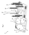
ここで、本発明の好ましい実施形態を説明する目的で、図面を詳細に参照し、本発明の交換ステーション2を、図1に示す。
For the purpose of illustrating a preferred embodiment of the invention, reference will now be made in detail to the drawings, and an
図1は、本発明に係る交換ステーション2の斜視図である。交換ステーション2は、取り外し部4及び取り付け部6が設けられたフレーム50を備える。
FIG. 1 is a perspective view of an
取り外し部4は、プレート形状を有する支持部材8を備える。支持部材8は、ロボット搭載型表面処理用工具(例えば、図2に示す研磨機)の先端に取り付けられた表面処理用媒体(例えば、図2に示すような、紙やすり等のシート状部材)24を受容するよう構成される。支持部材8は、支持部材8の大部分を囲むフレーム50よりも下の位置に設けられる。支持部材8は、円形の表面処理用媒体を受容し、円形の表面処理用媒体を支持部材8に沿って移動させるよう構成される。これにより、表面処理用媒体を支持部材8から取り外す。取り外し部4の3軸であるX、Y、およびZを示す。
The
取り外し部4は、分離ブレードとして形成された、支持部材8の隣接縁から短い距離をあけて設けられたプレート12を備える。プレート12は、支持部材8よりもわずかに高い位置に設けられる。これにより、プレート12及び支持部材8の間に隙間(図2参照)ができる。この隙間は、表面処理用媒体の縁部を受容できる程度の大きさを有する。
The
図2に示すように、表面処理用媒体を表面処理用工具のヘッドから取り外すには、表面処理用媒体の縁部がプレート12及び支持部材8の間の隙間に入るような位置に、表面処理用媒体を移動させ、ロボット搭載型表面処理用工具を、支持部材8の表面に沿って、プレート12に向かう方向に(X軸に沿って)移動させればよい。
To remove the surface treatment medium from the head of the surface treatment tool, as shown in FIG. The robot-mounted surface treatment tool may be moved along the surface of the
取り外し部4は、所定の距離をあけて配置された、2本の検知ピン14,14′を備える。このため、検知ピン14,14′を使用して、表面処理用媒体を受容するよう構成された、表面処理用工具のヘッドの対応する孔を検知できる。これにより、表面処理用工具のヘッドが所望の所定向きとなるよう、表面処理用工具のヘッドを配置することができる。
The
取り付け部6は、(媒体を受容するよう構成された)円形のベース部22を備える。2つの取り付け構造18,18′が、ベース部22に設けられる。取り付け構造18,18′は、取り外し可能に取り付けられたガイドピン34,34′を受容するような形状を有する。取り付け時、ガイドピン34,34′は、Z軸に沿って、ベース部22から突出する。
The mounting
ピン形状の当たり部材20として形成された複数の媒体ホルダ20が、ベース部22を囲む。媒体ホルダ20は、取り付け構造18,18′及びガイドピン34,34′に対して平行に延伸し、ベース部22を囲むフレーム50から突出する。取り付け構造18,18′のそれぞれには、対応する34,34′の近位部分における、雄型の合致部を受容するよう構成された、遠位雌型受容構造が設けられている。
A plurality of
複数の表面処理用媒体片が取り付け部6に積み重ねられている場合、表面処理用媒体を正しい向きに保つよう、ピン形状の媒体ホルダ20が形成・配置されている。
A pin-shaped
交換ステーション2には、取付面(例えば、テーブルやその他の作業台)に取り付けるための孔が設けられている。
The
通常の使用時において、Z軸が垂直に延びるよう、交換ステーション2の向きが決定される。
In normal use, the
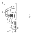
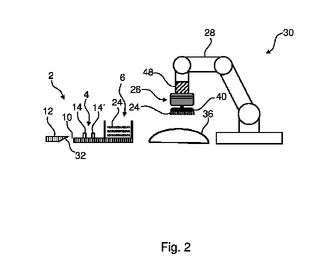
図2は、ロボット30に隣接して配置された、本発明に係る交換ステーション2の模式側面図を示す。ロボット30は、多関節ロボットアーム28を備える。表面処理用工具26は、ロボットアーム28に取り付けられている。図2に示す本実施形態では、表面処理用工具26は、研磨機26であり、研磨機26は、紙やすり等のシート状の表面処理用媒体24を受容するよう構成された、パッドとして形成されたヘッド40を備える。
FIG. 2 shows a schematic side view of an
力及び/又はトルクを検知するよう構成されたセンサ48が、ロボットアーム28に取り付けられている、又はロボットアーム28又は表面処理用工具26に交互に一体化されている。
A
表面処理用工具26は、表面処理が必要な対象物36の上方に配置される。
The
本発明に係る交換ステーション2は、ロボット30に隣接して配置される。交換ステーション2は、図1を参照して示し、説明したものに相当する。複数の表面処理用媒体24が交換ステーション2の取り付け部6に積み重ねられていることが分かる。
The
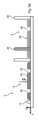
図3Aは、本発明に係る交換ステーション2を示す。本構成において、表面処理用媒体24の束が、すでに交換ステーション2の取り付け部6に受容されている。表面処理用媒体24は、交換ステーション2の取り付け部6の受容領域内に保持され、前記受容領域は、棒状の当たり部材20として設けられた媒体ホルダ20によって囲まれている。
FIG. 3A shows an
表面処理用媒体24が、それぞれ孔38を有し、取り付け部6が、表面処理用媒体24の孔のうちの1つを通って延伸するガイドピン34を備えていることが見て取れる。
It can be seen that the
表面処理用工具のヘッド40(図示略)は、交換ステーション2の取り外し部4の支持部材に載置される。多数の孔42がヘッド40に形成される。表面処理用媒体24の孔38は、ヘッド40に設けられた孔42と揃えられるよう、設けられる。これにより、表面処理用媒体24の使用時、孔38,42を介して、表面処理用媒体24から粉塵を除去することができる。
A head 40 (not shown) of a surface treatment tool is placed on a support member of the
取り外し部4は、所定の距離をあけて配置される2本の検知ピン14を備える(ただし、図3Aでは1つのみ示す)。検知ピン14を用いて、ヘッド40(図2参照)の対応する孔42を検知し、検知ピン14が孔42内に受容されるようにする。これにより、ヘッド40を所望の所定向きに配置することができる。
The
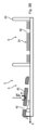
図3Bは、図3Aに示す交換ステーション2の他の図を示す。本構成において、図2を参照して示し、説明したセンサによって測定された力F及び/又はトルクTデータに基づいて、ヘッド40の孔42を検知する。実際には、ヘッド40の孔42によって検知ピン14が受容され、想定される力F及び/又はトルクTデータがセンサによって測定されるまで、ロボットアームは表面処理用工具を回転させる。
FIG. 3B shows another view of the
図4Aは、図3A及び図3Bに示す交換ステーション2の他の図を示す。本構成において、検知ピン14は、ヘッド40の孔に受容され、該孔と位置が揃えられている。所定の力F1が掛けられることで、ヘッド40を下向きに(Z軸に沿って)押圧する。表面処理用工具(図2参照)が取り付けられたロボットアームの1つ以上の位置センサを用いることで、ヘッド40の垂直方向の位置を検知することができる。この垂直方向の位置測定に基づいて、参照レベル(z値が0である位置)が確立される。
FIG. 4A shows another view of the
図4Bは、図3A及び図3Bに示す交換ステーション2の他の図を示す。本構成において、ヘッド40は、交換ステーション2の取り付け部6の受容領域に配置された、表面処理用媒体24の束の上面に載置される。受容領域が棒状の媒体ホルダ20によって囲まれていることが見て取れる。
FIG. 4B shows another view of the
下向きの(Z軸に沿った)力Fがヘッド40に掛かる。したがって、ヘッド40は、表面処理用媒体24の束を押圧し、表面処理用媒体24のうちの1つがヘッド40に取り付けられる。一実施形態において、掛かる力は、5N~100Nの範囲である。
A downward force F (along the Z axis) is applied to the
図5は、図4Bに示す交換ステーション2の他の図を示す。本構成において、ヘッド40は、初期位置に戻って、表面処理用媒体24のヘッド40への取り付けが成功しているかどうかを確認する。図4Aに説明して示した力と同等の力F1を掛け、表面処理用工具(図2参照)が取り付けられたロボットアームの1つ以上の位置センサを用いることで、ヘッド40の垂直方向の位置を検知し、それにより、交換ステーション2の取り外し部4の支持部材8間の距離を決定することができる。交換ステーション2の取り外し部4の支持部材8間の距離が想定値と同等である場合、1つの表面処理用媒体24の、ヘッド40への取り付けが成功したと結論付けることができる。2枚の表面処理用媒体24をヘッド40へ取り付けてしまった場合、検知された距離は、想定距離よりも大きくなる。したがって、こうした試験手順により、複数枚の表面処理用媒体24がヘッド40に取り付けられているかどうかが分かる。
FIG. 5 shows another view of the
一実施形態において、表面処理用媒体24は、厚さ0.5mmを有する紙やすりである。この場合、想定値としては、0.5mmである。
In one embodiment,
一実施形態において、表面処理用媒体24は、厚さ1.0mmを有する紙やすりである。この場合、想定値としては、1.0mmである。
In one embodiment,
一実施形態において、表面処理用媒体24は、厚さ1.5mmを有する紙やすりである。この場合、想定値としては、1.5mmである。
In one embodiment,
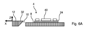
図6Aは、本発明に係る交換ステーション2の取り外し部4の断面図を示す。1つの表面処理用媒体24が、表面処理用工具(図示略)のヘッド40に取り付けられている。表面処理用媒体24が取り付けられたヘッド40が、交換ステーション2の取り外し部4の支持部材8上に載置されている。
FIG. 6A shows a cross-sectional view of the
取り外し部4は、分離ブレード32として構成された先端部を有するプレート12を備える。分離ブレード32は、支持部材8の隣接縁から近い距離に設けられる。プレート12の上部及び分離ブレード32は、支持部材8よりもわずかに高い位置に設けられている。これにより、分離ブレード32及び支持部材8の間に、隙間10ができる。この隙間10は、表面処理用媒体24の縁部を受容できる程度の大きさを有する。
The
一実施形態において、プレート12及び分離ブレード32が、互いに取り付けられている。一実施形態において、プレート12及び分離ブレード32は、一体型部材を構成するよう一体化される。
In one embodiment,
一実施形態において、分離ブレード32は、支持部材8に対して、移動可能に配置される。これにより、分離ブレード32を移動させて、隙間10の大きさを変更することができる。分離ブレード32の取り付けは、ねじやその他の取付部材によって行われ得る。
In one embodiment,
表面処理用工具(図2参照)が取り付けられたロボットアームの1つ以上の位置センサによって、ヘッド40及び支持部材8の間の距離を測定する。これにより、ヘッド40の垂直方向の位置を検知することができる。
The distance between the
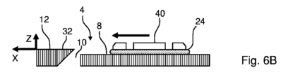
図6Bは、図6Aに示す取り外し部4の他の断面図を示す。表面処理用工具(図示略)のヘッド40が、X軸に沿って左側に移動したことが見て取れる。ヘッド40の移動を、矢印で示す。
FIG. 6B shows another cross-sectional view of the
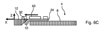
図6Cは、図6Bに示す取り外し部4の他の断面図を示す。表面処理用媒体24が、分離ブレード32及び支持部材8の間の隙間10に入り込んでいることが見て取れる。したがって、表面処理用媒体24は、ヘッド40から取り外されている。
FIG. 6C shows another cross-sectional view of the
図6Dは、図6Cに示す取り外し部の他の断面図を示す。本構成において、ヘッド40が、図6Aで示された位置と同じ位置に配置され、表面処理用工具(図2参照)が取り付けられたロボットアームの1つ以上の位置センサによって、ヘッド40の垂直方向の位置(又はヘッド40及び支持部材8の間の距離)が検知される。これにより、ヘッド40の垂直方向の位置を検知することができる。
FIG. 6D shows another cross-sectional view of the removal section shown in FIG. 6C. In this configuration, the
ヘッド40及び支持部材8の間の距離が想定通りであった(ヘッド40及び支持部材8の間の距離が、図6Aで説明した値と同等であった)場合、表面処理用媒体24の取り外しに成功したと結論付けられる。
If the distance between the
図7Aは、本発明に係る交換ステーションの取り付け部6の断面図を示す。表面処理用工具(図示略)のヘッド40は、取り付け部6の支持部材に載置された表面処理用媒体24の束上に、載置される。この束は、棒状の当たり部材20として設けられた媒体ホルダ20によって、囲まれる。媒体ホルダ20は、互いに貼りついている表面処理用媒体24の隣接片を離間させるために採用された表面構造を有している。媒体ホルダ20の表面構造は、突出構造44及び溝構造46を交互に有する部分を備える。図7Aでは、突出構造44及び溝構造46の大きさを、説明のため、強調して示している。
FIG. 7A shows a cross-sectional view of the mounting
表面処理用媒体24をヘッド40に取り付けるために、ヘッド40から表面処理用媒体24の束に向けて、力Fを掛ける。
To attach the
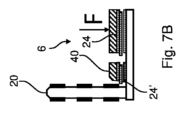
図7Bは、図7Aに示す取り付け部6の左側部を示す、他の断面図である。ヘッド40及び取り付けられた表面処理用媒体24は、所定のレベルの力を利用して、わずかに右へ移動する。
FIG. 7B is another sectional view showing the left side of the
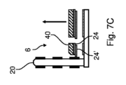
図7Cは、図7Bに示す取り付け部6の一部を示す、他の断面図である。本構成において、ヘッド40及び取り付けられた表面処理用媒体24は、残りの表面処理用媒体24の束から上に持ち上げられる。したがって、ヘッド40及び取り付けられた表面処理用媒体24は、上方向に向かって移動する。2つの表面処理用媒体24がヘッド40に取り付けられていることが見て取れる。
FIG. 7C is another cross-sectional view showing a part of the
図7Dは、図7Cに示す取り付け部6の一部を示す、他の断面図である。最下部に位置する表面処理用媒体24を、ヘッド40と接触し、取り付けられている表面処理用媒体24から引き離すため、ヘッド40を隣接する媒体ホルダ20に向けて移動する。
FIG. 7D is another cross-sectional view showing a part of the
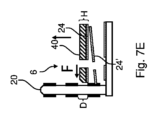
図7Eは、図7Dに示す取り付け部6の一部を示す、他の断面図である。最下部に位置する表面処理用媒体24を、ヘッド40と接触し、取り付けられている表面処理用媒体24から引き離すため、ヘッド40及び表面処理用媒体24の、隣接する媒体ホルダ20への接触を保持するよう、ヘッド40が隣接する媒体ホルダ20に対して押圧されている状態で、取り付け部4の支持部材から離間する方向に上に向かってヘッド40を移動させる。したがって、突出構造44により、最上部に位置する表面処理用媒体24から、最下部に位置する表面処理用媒体24を引き離し、ヘッド40が溝構造46に受容されたままでありつつ、最下部に位置する表面処理用媒体24は受容されていない状態となる。基本的に、最上部に位置する(貼りついた)表面処理用媒体は、溝構造46に入り込み、ここで、最下部に位置する表面処理用媒体24から離間する。図7Eでは、隣接した突出構造44の間の距離Dが、溝構造46が最上部に位置する表面処理用媒体24及びヘッド40を受容できる程度の大きさを有していることが見て取れ、最上部に位置する表面処理用媒体24及びヘッド40の厚みがHで示されている。ヘッド40の、最上部に位置する部分はテーパー状となっているため、DをHよりも大きくする必要はない。さらに、ヘッド40は、圧縮性材料からなり得る。ヘッド40が圧縮材料からなる場合、HがDよりもわずかに大きかったとしても、最下部に位置する表面処理用媒体24を引き離すことができる。これは、ヘッド40の最下部に位置する部分が、溝構造46によって受容され得るためである。これにより、溝構造46によって、ヘッド40の最下部に位置する部分及び最上部に位置する表面処理用媒体24を受容することができる。
FIG. 7E is another cross-sectional view showing a part of the
最下部に位置する表面処理用媒体24が最上部に位置する表面処理用媒体24及びヘッド40に向けて突出している場合、最下部に位置する表面処理用媒体24の一部を溝構造46に位置させて取り外すことができ、最上部に位置する表面処理用媒体24及びヘッド40を、隣接する媒体ホルダ20の全長に沿って移動させることができる。
When the
2 交換ステーション(グリットチェンジャ)
4 取り外し部
6 取り付け部
8 支持部材
10 隙間
12 プレート
14,14′ ピン
18,18′ 取り付け構造
20 媒体ホルダ(当たり部材)
22 ベース部(媒体用)
24 表面処理用媒体(例えば、紙やすり等のシート状部材)
26 ロボット搭載型表面処理用工具(例えば、研磨機)
28 ロボットアーム
30 ロボット
32 分離ブレード
34,34′ ガイドピン
36 対象物
38 孔
40 ヘッド(例えば、パッドからなる)
42 孔
44 表面構造(突出構造)
46 表面構造(溝構造)
48 センサ
50 フレーム
F,F1 力
T トルク
D 距離
H 厚み
2 Exchange station (grit changer)
4
22 Base part (for media)
24 Surface treatment medium (e.g., sheet-like member such as sandpaper)
26 Robot-mounted surface treatment tools (e.g. polishing machines)
28
42
46 Surface structure (groove structure)
48
Claims (15)
前記ロボットアーム(28)又は前記表面処理用工具(26)の、1つ以上の位置センサにより、前記ヘッド(40)及び前記表面(8)の間の距離を測定する工程と、
前記表面処理用媒体(24)を前記ヘッド(40)に取り付け、前記表面処理用媒体(24)が前記ヘッド(40)に取り付けられている場合に、前記ヘッド(40)を前記表面(8)に載置する工程と、
前記表面処理用媒体(24)が前記ヘッド(40)に取り付けられている場合に、前記ロボットアーム(28)又は前記表面処理用工具(26)の前記1つ以上の位置センサによって、前記ヘッド(40)及び前記表面(8)の間の距離を測定する工程とを備える方法。 A method for automatically attaching a surface treatment medium (24) to a surface treatment tool (26) equipped on a robot arm (28) of a robot (30) equipped with an articulated robot arm (28), the method comprising: The surface treatment tool (26) includes a head (40) configured to receive the surface treatment medium (24), and the method includes placing the head (40) on a surface (8). , applying a predetermined force (F 1 ) to press the head (40) toward the surface (8) when the surface treatment medium (24) is not attached to the head (40); Equipped with a process,
measuring the distance between the head (40) and the surface (8) by one or more position sensors of the robot arm (28) or the surface treatment tool (26);
The surface treatment medium (24) is attached to the head (40), and when the surface treatment medium (24) is attached to the head (40), the head (40) is attached to the surface (8). a step of placing the
When the surface treatment medium (24) is attached to the head (40), the one or more position sensors of the robot arm (28) or the surface treatment tool (26) 40) and measuring the distance between said surfaces (8).
前記表面処理用媒体(24)が取り外された際に、前記ヘッド(40)を前記表面(8)に載置する工程と、
前記所定の力(F1)を掛けて、前記ヘッド(40)を前記表面(8)に向けて押圧する工程と、
前記ロボットアーム(28)又は前記表面処理用工具(26)の前記1つ以上の位置センサによって、前記ヘッド(40)及び前記表面(8)の間の距離を測定する工程と、
をさらに備えることを特徴とする、請求項1に記載の方法。 removing the surface treatment medium (24) from the head (40);
placing the head (40) on the surface (8) when the surface treatment medium (24) is removed;
applying the predetermined force (F 1 ) to press the head (40) toward the surface (8);
measuring the distance between the head (40) and the surface (8) by the one or more position sensors of the robot arm (28) or the surface treatment tool (26);
2. The method of claim 1, further comprising:
をさらに備えることを特徴とする、請求項1又は2に記載の方法。 detecting the orientation of the head (40) by locking the head (40) to a locking structure (14, 14');
The method according to claim 1 or 2, further comprising:
前記係止構造(14,14′)は、互いに所定の距離をあけて設けられた2本の検知ピン(14,14′)を備え、
前記検知ピン(14,14′)は、前記ヘッド(40)の前記孔(42)と係合するよう構成されることを特徴とする、請求項3に記載の方法。 The head (40) has a plurality of holes (42),
The locking structure (14, 14') includes two detection pins (14, 14') provided at a predetermined distance from each other,
4. A method according to claim 3, characterized in that the sensing pin (14, 14') is configured to engage the hole (42) of the head (40).
をさらに備えることを特徴とする、請求項1から4のいずれか一項に記載の方法。 a removal portion (4) configured to remove the surface treatment medium (24) from the head (40); and an attachment portion (4) configured to attach the surface treatment medium (24) to the head (40). 6) installing an exchange station (2) comprising;
5. A method according to any one of claims 1 to 4, further comprising:
をさらに備えることを特徴とする、請求項1から6のいずれか一項に記載の方法。 If one or more surface treatment media (24) are detected to be attached to the head (40), at least the most distal end of the head (40) is brought into contact with the media holder (20) and the media By moving the head (40) along the entire length of the holder (20), the surface treatment medium (24) located at the bottom is removed, and the process
7. A method according to any one of claims 1 to 6, characterized in that it further comprises:
前記交換ステーション(2)は、請求項1から8のいずれか一項に記載の方法を実行するよう構成され、
前記表面処理用工具(26)は、前記表面処理用媒体(24)を受容するよう構成されたヘッド(40)を備え、
前記交換ステーション(2)は、取り外し部(4)と、取り付け部(6)と、を備え、
前記取り外し部(4)は、前記ヘッド(40)を受容するよう構成された支持部材(8)を備え、
前記取り外し部(4)は、前記支持部材(8)から突出し、所定の相互距離をもって配置された2本の検知ピン(14,14′)を備え、
前記取り付け部(6)は、ベース部(22)を備え、
2本のガイドピン(34,34′)が前記ベース部(22)から突出し、
前記2本のガイドピン(34,34′)は、前記2本の検知ピン(14,14′)と同じ相互距離をもって配置されることを特徴とする、交換ステーション(2)。 An exchange station (for automatically attaching a surface treatment medium (24) to a surface treatment tool (26) equipped on a robot arm (28) of a robot (30) equipped with an articulated robot arm (28) 2) and
The exchange station (2) is configured to carry out the method according to any one of claims 1 to 8,
The surface treatment tool (26) includes a head (40) configured to receive the surface treatment medium (24);
The exchange station (2) includes a removal part (4) and an attachment part (6),
The removal portion (4) comprises a support member (8) configured to receive the head (40);
The removal part (4) includes two detection pins (14, 14') protruding from the support member (8) and arranged at a predetermined distance from each other,
The attachment part (6) includes a base part (22),
Two guide pins (34, 34') protrude from the base part (22),
Exchange station (2), characterized in that said two guide pins (34, 34') are arranged with the same mutual distance as said two detection pins (14, 14').
前記取り付け部(6)は、ピン形状の当たり部材として形成された複数の媒体ホルダ(20)を備え、該複数の媒体ホルダ(20)は、前記媒体ホルダ(20)が前記ベース部(22)を囲むような構成で配置されることを特徴とする、請求項9又は10に記載の交換ステーション(2)。 The mounting portion (6) comprises a base portion (22) configured to receive a bundle of surface treatment media (24);
The attachment part (6) comprises a plurality of medium holders (20) formed as pin-shaped abutting members, the plurality of medium holders (20) being arranged such that the medium holders (20) are connected to the base part (22). Exchange station (2) according to claim 9 or 10, characterized in that it is arranged in a configuration surrounding the exchange station (2).
前記分離ブレード(32)は、前記支持部材(8)よりもわずかに高い位置に設けられることを特徴とする、請求項11に記載の交換ステーション(2)。 The removal part (4) comprises a separation blade (32) provided at a distance from an adjacent edge of the support member (8);
Exchange station (2) according to claim 11, characterized in that the separation blade (32) is provided at a slightly higher level than the support member (8).
-ロボットアーム(28)を備えるロボット(30)と、
-前記ロボットアーム(28)に取り付けられる表面処理用工具(26)と、
を備え、
前記ロボットシステムは、表面処理用媒体(24)を前記表面処理用工具(26)に自動で取り付けるよう構成され、
前記表面処理用工具(26)は、前記表面処理用媒体(24)を受容するよう構成されたヘッド(40)を備え、
前記ロボットシステムは、前記ヘッド(40)を表面(8)に載置し、前記表面処理用媒体(24)が前記ヘッド(40)に取り付けられていない場合に、所定の力(F1)を掛けて、前記ヘッド(40)を前記表面(8)に向けて押圧するよう構成されることを特徴とする、ロボットシステム。 - an exchange station (2) according to any one of claims 9 to 13;
- a robot (30) with a robot arm (28);
- a surface treatment tool (26) attached to the robot arm (28);
Equipped with
the robotic system is configured to automatically apply a surface treatment medium (24) to the surface treatment tool (26);
The surface treatment tool (26) includes a head (40) configured to receive the surface treatment medium (24);
The robot system places the head (40) on the surface (8) and applies a predetermined force (F 1 ) when the surface treatment medium (24) is not attached to the head (40). Robotic system, characterized in that it is configured to press the head (40) towards the surface (8).
表面処理用媒体(24)を前記ヘッド(40)に取り付け、前記表面処理用媒体(24)が前記ヘッド(40)に取り付けられている場合に、前記ヘッド(40)を前記支持部材(8)に載置するよう構成された取り付け部と、
を備えるロボットシステムであって、
前記測定部は、前記表面処理用媒体(24)が前記ヘッド(40)に取り付けられ、前記ヘッド(40)が前記支持部材(8)に載置されている場合に、前記ヘッド(40)及び前記支持部材(8)の間の距離を測定するよう構成されることを特徴とする、請求項14に記載のロボットシステム。 a measuring unit configured to measure the distance between the head (40) and the support member (8) by one or more position sensors of the robot arm (28) or the surface treatment tool (26); ,
A surface treatment medium (24) is attached to the head (40), and when the surface treatment medium (24) is attached to the head (40), the head (40) is attached to the support member (8). a mounting portion configured to rest on the
A robot system comprising:
The measurement unit is configured to measure the surface treatment medium (24) when the head (40) is attached to the head (40) and the head (40) is placed on the support member (8). Robot system according to claim 14, characterized in that it is configured to measure the distance between the support members (8).
Applications Claiming Priority (5)
| Application Number | Priority Date | Filing Date | Title |
|---|---|---|---|
| DKPA202000989 | 2020-09-02 | ||
| DKPA202000989A DK180696B1 (en) | 2020-09-02 | 2020-09-02 | Procedure for replacing sandpaper |
| DKPA202100221A DK180697B1 (en) | 2020-09-02 | 2021-03-02 | Replacement station and robot system |
| DKPA202100221 | 2021-03-02 | ||
| PCT/DK2021/050266 WO2022048719A1 (en) | 2020-09-02 | 2021-08-31 | Changing station, method for changing sandpaper and robot system |
Publications (2)
| Publication Number | Publication Date |
|---|---|
| JP2023540468A true JP2023540468A (en) | 2023-09-25 |
| JP7755327B2 JP7755327B2 (en) | 2025-10-16 |
Family
ID=78770291
Family Applications (1)
| Application Number | Title | Priority Date | Filing Date |
|---|---|---|---|
| JP2023513425A Active JP7755327B2 (en) | 2020-09-02 | 2021-08-31 | Exchange station, method for changing sandpaper, and robot system |
Country Status (6)
| Country | Link |
|---|---|
| US (1) | US20230201990A1 (en) |
| EP (1) | EP4208317A4 (en) |
| JP (1) | JP7755327B2 (en) |
| KR (1) | KR20230058381A (en) |
| DK (2) | DK180696B1 (en) |
| WO (1) | WO2022048719A1 (en) |
Families Citing this family (1)
| Publication number | Priority date | Publication date | Assignee | Title |
|---|---|---|---|---|
| FI20195131A1 (en) * | 2019-02-20 | 2020-08-21 | Mirka Ltd | Device for changing abrasive products |
Citations (4)
| Publication number | Priority date | Publication date | Assignee | Title |
|---|---|---|---|---|
| JPH0352060U (en) * | 1989-09-21 | 1991-05-21 | ||
| JPH0593735U (en) * | 1992-05-18 | 1993-12-21 | 三菱自動車工業株式会社 | Tool changer for machine tools |
| US20190152015A1 (en) * | 2016-04-04 | 2019-05-23 | Ferrobotics Compliant Robot Technology Gmbh | Changing Station for the Automatic Changing of Grinding Materials |
| DE102020101384A1 (en) * | 2019-01-23 | 2020-07-23 | Ferrobotics Compliant Robot Technology Gmbh | ROBOT-BASED GRINDING DEVICE WITH INTEGRATED MAINTENANCE UNIT |
Family Cites Families (7)
| Publication number | Priority date | Publication date | Assignee | Title |
|---|---|---|---|---|
| FR2636591A1 (en) * | 1988-09-22 | 1990-03-23 | Inocar | Machine for automatic replacement of polishing discs on the tool heads of robot-operated sanders |
| US5231803A (en) * | 1992-04-13 | 1993-08-03 | Minnesota Mining And Manufacturing Company | Automated random orbital abrading method |
| ES2338622B1 (en) * | 2008-07-23 | 2011-07-01 | Estudios De Ingenieria Adaptada, S.L. | TOOL POSITIONING HEAD ON IRREGULAR SURFACES. |
| FR2999107B1 (en) * | 2012-12-10 | 2015-01-09 | Univ Nantes | SANDING DEVICE COMPRISING ABRASIVE DISC CHANGE MEANS |
| EP3107686B1 (en) * | 2014-02-20 | 2018-02-07 | Fabrica Machinale S.r.l. | Apparatus for changing an abrasive sheet in an abrading machine |
| ES2630104T3 (en) * | 2014-07-15 | 2017-08-18 | Rud. Starcke Gmbh & Co. Kg | Method and accessory for mounting a grinding disc to a manual grinder |
| US11565370B2 (en) * | 2017-12-20 | 2023-01-31 | Fabrica Machinale S.R.L. | Method and apparatus for carrying out the replacement of an abrasive element in a machine for working surfaces |
-
2020
- 2020-09-02 DK DKPA202000989A patent/DK180696B1/en active IP Right Grant
-
2021
- 2021-03-02 DK DKPA202100221A patent/DK180697B1/en active IP Right Grant
- 2021-08-31 WO PCT/DK2021/050266 patent/WO2022048719A1/en not_active Ceased
- 2021-08-31 JP JP2023513425A patent/JP7755327B2/en active Active
- 2021-08-31 KR KR1020237005887A patent/KR20230058381A/en active Pending
- 2021-08-31 EP EP21863760.1A patent/EP4208317A4/en active Pending
-
2023
- 2023-03-01 US US18/116,045 patent/US20230201990A1/en active Pending
Patent Citations (4)
| Publication number | Priority date | Publication date | Assignee | Title |
|---|---|---|---|---|
| JPH0352060U (en) * | 1989-09-21 | 1991-05-21 | ||
| JPH0593735U (en) * | 1992-05-18 | 1993-12-21 | 三菱自動車工業株式会社 | Tool changer for machine tools |
| US20190152015A1 (en) * | 2016-04-04 | 2019-05-23 | Ferrobotics Compliant Robot Technology Gmbh | Changing Station for the Automatic Changing of Grinding Materials |
| DE102020101384A1 (en) * | 2019-01-23 | 2020-07-23 | Ferrobotics Compliant Robot Technology Gmbh | ROBOT-BASED GRINDING DEVICE WITH INTEGRATED MAINTENANCE UNIT |
Also Published As
| Publication number | Publication date |
|---|---|
| WO2022048719A1 (en) | 2022-03-10 |
| JP7755327B2 (en) | 2025-10-16 |
| EP4208317A4 (en) | 2024-10-16 |
| DK202000989A1 (en) | 2021-12-02 |
| US20230201990A1 (en) | 2023-06-29 |
| DK202100221A1 (en) | 2021-12-02 |
| DK180697B1 (en) | 2021-12-02 |
| KR20230058381A (en) | 2023-05-03 |
| EP4208317A1 (en) | 2023-07-12 |
| DK180696B1 (en) | 2021-12-02 |
Similar Documents
| Publication | Publication Date | Title |
|---|---|---|
| EP2463056B1 (en) | Robotic surface preparation by a random orbital device | |
| US5377455A (en) | Automated random orbital abrading system and method | |
| CN111491759B (en) | Method and apparatus for abrasive element replacement in machines for working surfaces | |
| JP5667268B2 (en) | Polishing tool for use as a chemical mechanical flattening pad conditioner | |
| CN107914215B (en) | Dressing method for grinding tools | |
| US8192255B2 (en) | Tool holder with tapered slot for a grinding machine | |
| US9089944B2 (en) | Device, tool and method for machining of an optical lens | |
| CN101500752A (en) | Sanding tool | |
| KR20180044810A (en) | Grinding apparatus | |
| JP5072020B2 (en) | Grinding member dressing method and grinding apparatus | |
| US20250242466A1 (en) | Abrasive article attachment systems and methods | |
| JP7755327B2 (en) | Exchange station, method for changing sandpaper, and robot system | |
| US20030060144A1 (en) | Apparatus and method for conditioning a contact surface of a processing pad used in processing microelectronic workpieces | |
| CN220660391U (en) | Multifunctional five-axis polishing machine | |
| CN211916531U (en) | Polishing tool | |
| CN115666849A (en) | Laboratory disc grinding device, method, replacement grinding disc and application of grinding disc | |
| EP1657023B1 (en) | Grinding jig set and grinding method | |
| AU2022419398A1 (en) | Machine, adapter sanding block, assembly and method of operation | |
| CN219819341U (en) | Sand paper gravel layer removing equipment | |
| CN222755122U (en) | Polishing device | |
| KR20050096618A (en) | Grinding machine for a nail scissors | |
| CN120023738A (en) | Grinding devices and grinding equipment | |
| JPH06226602A (en) | Polishing method | |
| CN112894614A (en) | Grinding tool replacing device | |
| JPH08521U (en) | Polishing tool |
Legal Events
| Date | Code | Title | Description |
|---|---|---|---|
| A621 | Written request for application examination |
Free format text: JAPANESE INTERMEDIATE CODE: A621 Effective date: 20240709 |
|
| A131 | Notification of reasons for refusal |
Free format text: JAPANESE INTERMEDIATE CODE: A131 Effective date: 20250422 |
|
| A977 | Report on retrieval |
Free format text: JAPANESE INTERMEDIATE CODE: A971007 Effective date: 20250423 |
|
| A601 | Written request for extension of time |
Free format text: JAPANESE INTERMEDIATE CODE: A601 Effective date: 20250722 |
|
| A521 | Request for written amendment filed |
Free format text: JAPANESE INTERMEDIATE CODE: A523 Effective date: 20250820 |
|
| TRDD | Decision of grant or rejection written | ||
| A01 | Written decision to grant a patent or to grant a registration (utility model) |
Free format text: JAPANESE INTERMEDIATE CODE: A01 Effective date: 20250909 |
|
| A61 | First payment of annual fees (during grant procedure) |
Free format text: JAPANESE INTERMEDIATE CODE: A61 Effective date: 20250926 |
|
| R150 | Certificate of patent or registration of utility model |
Ref document number: 7755327 Country of ref document: JP Free format text: JAPANESE INTERMEDIATE CODE: R150 |