JP2024527770A - Impact-resistant partitions containing solid electrolyte ceramics for electrolytic cells - Google Patents
Impact-resistant partitions containing solid electrolyte ceramics for electrolytic cells Download PDFInfo
- Publication number
- JP2024527770A JP2024527770A JP2024502006A JP2024502006A JP2024527770A JP 2024527770 A JP2024527770 A JP 2024527770A JP 2024502006 A JP2024502006 A JP 2024502006A JP 2024502006 A JP2024502006 A JP 2024502006A JP 2024527770 A JP2024527770 A JP 2024527770A
- Authority
- JP
- Japan
- Prior art keywords
- partition wall
- electrolytic cell
- solid electrolyte
- alkali metal
- internal structure
- Prior art date
- Legal status (The legal status is an assumption and is not a legal conclusion. Google has not performed a legal analysis and makes no representation as to the accuracy of the status listed.)
- Pending
Links
Images

Classifications
-
- C—CHEMISTRY; METALLURGY
- C25—ELECTROLYTIC OR ELECTROPHORETIC PROCESSES; APPARATUS THEREFOR
- C25B—ELECTROLYTIC OR ELECTROPHORETIC PROCESSES FOR THE PRODUCTION OF COMPOUNDS OR NON-METALS; APPARATUS THEREFOR
- C25B13/00—Diaphragms; Spacing elements
- C25B13/02—Diaphragms; Spacing elements characterised by shape or form
-
- C—CHEMISTRY; METALLURGY
- C25—ELECTROLYTIC OR ELECTROPHORETIC PROCESSES; APPARATUS THEREFOR
- C25B—ELECTROLYTIC OR ELECTROPHORETIC PROCESSES FOR THE PRODUCTION OF COMPOUNDS OR NON-METALS; APPARATUS THEREFOR
- C25B13/00—Diaphragms; Spacing elements
- C25B13/04—Diaphragms; Spacing elements characterised by the material
- C25B13/05—Diaphragms; Spacing elements characterised by the material based on inorganic materials
- C25B13/07—Diaphragms; Spacing elements characterised by the material based on inorganic materials based on ceramics
-
- C—CHEMISTRY; METALLURGY
- C25—ELECTROLYTIC OR ELECTROPHORETIC PROCESSES; APPARATUS THEREFOR
- C25B—ELECTROLYTIC OR ELECTROPHORETIC PROCESSES FOR THE PRODUCTION OF COMPOUNDS OR NON-METALS; APPARATUS THEREFOR
- C25B3/00—Electrolytic production of organic compounds
- C25B3/01—Products
- C25B3/07—Oxygen containing compounds
-
- C—CHEMISTRY; METALLURGY
- C25—ELECTROLYTIC OR ELECTROPHORETIC PROCESSES; APPARATUS THEREFOR
- C25B—ELECTROLYTIC OR ELECTROPHORETIC PROCESSES FOR THE PRODUCTION OF COMPOUNDS OR NON-METALS; APPARATUS THEREFOR
- C25B3/00—Electrolytic production of organic compounds
- C25B3/01—Products
- C25B3/13—Organo-metallic compounds
-
- C—CHEMISTRY; METALLURGY
- C25—ELECTROLYTIC OR ELECTROPHORETIC PROCESSES; APPARATUS THEREFOR
- C25B—ELECTROLYTIC OR ELECTROPHORETIC PROCESSES FOR THE PRODUCTION OF COMPOUNDS OR NON-METALS; APPARATUS THEREFOR
- C25B3/00—Electrolytic production of organic compounds
- C25B3/20—Processes
- C25B3/25—Reduction
-
- C—CHEMISTRY; METALLURGY
- C25—ELECTROLYTIC OR ELECTROPHORETIC PROCESSES; APPARATUS THEREFOR
- C25B—ELECTROLYTIC OR ELECTROPHORETIC PROCESSES FOR THE PRODUCTION OF COMPOUNDS OR NON-METALS; APPARATUS THEREFOR
- C25B9/00—Cells or assemblies of cells; Constructional parts of cells; Assemblies of constructional parts, e.g. electrode-diaphragm assemblies; Process-related cell features
- C25B9/17—Cells comprising dimensionally-stable non-movable electrodes; Assemblies of constructional parts thereof
- C25B9/19—Cells comprising dimensionally-stable non-movable electrodes; Assemblies of constructional parts thereof with diaphragms
- C25B9/21—Cells comprising dimensionally-stable non-movable electrodes; Assemblies of constructional parts thereof with diaphragms two or more diaphragms
-
- C—CHEMISTRY; METALLURGY
- C25—ELECTROLYTIC OR ELECTROPHORETIC PROCESSES; APPARATUS THEREFOR
- C25B—ELECTROLYTIC OR ELECTROPHORETIC PROCESSES FOR THE PRODUCTION OF COMPOUNDS OR NON-METALS; APPARATUS THEREFOR
- C25B9/00—Cells or assemblies of cells; Constructional parts of cells; Assemblies of constructional parts, e.g. electrode-diaphragm assemblies; Process-related cell features
- C25B9/60—Constructional parts of cells
-
- Y—GENERAL TAGGING OF NEW TECHNOLOGICAL DEVELOPMENTS; GENERAL TAGGING OF CROSS-SECTIONAL TECHNOLOGIES SPANNING OVER SEVERAL SECTIONS OF THE IPC; TECHNICAL SUBJECTS COVERED BY FORMER USPC CROSS-REFERENCE ART COLLECTIONS [XRACs] AND DIGESTS
- Y02—TECHNOLOGIES OR APPLICATIONS FOR MITIGATION OR ADAPTATION AGAINST CLIMATE CHANGE
- Y02E—REDUCTION OF GREENHOUSE GAS [GHG] EMISSIONS, RELATED TO ENERGY GENERATION, TRANSMISSION OR DISTRIBUTION
- Y02E60/00—Enabling technologies; Technologies with a potential or indirect contribution to GHG emissions mitigation
- Y02E60/10—Energy storage using batteries
Landscapes
- Chemical & Material Sciences (AREA)
- Organic Chemistry (AREA)
- Engineering & Computer Science (AREA)
- Chemical Kinetics & Catalysis (AREA)
- Electrochemistry (AREA)
- Materials Engineering (AREA)
- Metallurgy (AREA)
- Ceramic Engineering (AREA)
- Inorganic Chemistry (AREA)
- Electrolytic Production Of Non-Metals, Compounds, Apparatuses Therefor (AREA)
- Electrolytic Production Of Metals (AREA)
Abstract
本発明は、第1の態様では、電解槽E内での使用に適した仕切壁Wに関する。仕切壁Wは、端要素RRと分離要素RTとを形成する枠要素Rを備えている。枠要素Rは、2つの対向する部分R1およびR2を備え、それらの間には少なくとも2つのアルカリ金属陽イオン伝導性固体電解質セラミックFAおよびFBが配置される。分離要素RTは、仕切壁Wに含まれるアルカリ金属陽イオン伝導性固体電解質セラミックの間に位置し、これらを互いに分離する。本発明の特徴は、2つの部分R1およびR2が、少なくとも1つの固定要素BRにより端要素RRに、かつ少なくとも1つの固定要素BTにより分離要素RTに、互いに固定されている点である。仕切壁Wが一体型の固体電解質を含んでいる従来技術による場合と比較して、この配置は、第一に、個々のセラミックが、例えば収縮または膨張による温度変動に反応するために利用の自由度がより高いため、より柔軟である。これにより、セラミックの機械的応力に対する安定性が向上する。同時に、部分R1およびR2が、端要素RRおよび分離要素RTの両方において、少なくとも1つの固定要素BRまたはBTにより互いに固定されていることで、部分R1とR2の間の少なくとも2つの固体電解質セラミックの配置の機械的安定性が向上する。第2の態様では、本発明は、仕切壁Wによって隣接する室から区切られた陰極室KKを含む電解槽Eに関する。隣接する室とは、電解槽Eの陽極室KAまたは中間室KMである。第3の態様では、本発明は、本発明の第2の態様による電解槽E内でアルカリ金属アルコキシド溶液を製造する方法に関する。【選択図】図2The invention relates in a first aspect to a partition W suitable for use in an electrolytic cell E. The partition W comprises a frame element R forming an end element RR and a separation element RT. The frame element R comprises two opposing parts R1 and R2 between which at least two alkali metal cation conducting solid electrolyte ceramics FA and FB are arranged. The separation element RT is located between the alkali metal cation conducting solid electrolyte ceramics contained in the partition W and separates them from each other. A feature of the invention is that the two parts R1 and R2 are fixed to each other by at least one fixing element BR to the end element RR and by at least one fixing element BT to the separation element RT. Compared to the prior art case in which the partition W contains an integral solid electrolyte, this arrangement is firstly more flexible since the individual ceramics have more freedom of use to react to temperature variations, for example by contraction or expansion. This improves the stability of the ceramics against mechanical stresses. At the same time, the parts R1 and R2 are fixed to one another by at least one fixing element BR or BT, both at the end element RR and at the separating element RT, thereby improving the mechanical stability of the arrangement of at least two solid electrolyte ceramics between the parts R1 and R2. In a second aspect, the invention relates to an electrolytic cell E comprising a cathode chamber KK separated from an adjacent chamber by a partition wall W. The adjacent chamber is an anode chamber KA or an intermediate chamber KM of the electrolytic cell E. In a third aspect, the invention relates to a method for producing an alkali metal alkoxide solution in an electrolytic cell E according to the second aspect of the invention. [Selected Figure 2]
Description
本発明は、第1の態様では、電解槽E内での使用に適した仕切壁Wに関する。仕切壁Wは、端要素RRと分離要素RTとを形成する枠要素Rを含んでいる。枠要素Rは、2つの対向する部分R1およびR2を備え、それらの間には、少なくとも2つのアルカリ金属陽イオン伝導性固体セラミックFAおよびFBが配置されている。分離要素RTは、仕切壁Wに含まれるアルカリ金属陽イオン伝導性固体電解質セラミックの間に位置し、これらを互いに分離する。
本発明の特徴は、2つの部分R1およびR2が、少なくとも1つの固定要素BRにより端要素RRに、かつ少なくとも1つの固定要素BTにより分離要素RTに、互いに固定されている点である。
The invention relates in a first aspect to a partition W suitable for use in an electrolytic cell E. The partition W comprises a frame element R forming an end element R 1 R and a separating element R 2 T. The frame element R comprises two opposing parts R 1 and R 2 between which at least two alkali metal cation conducting solid ceramics F 1 A and
A feature of the invention is that the two parts R 1 and R 2 are fixed to one another by at least one fixing element B 2R to the end element R 2R and by at least one fixing element B 2T to the separating element R 2T .
仕切壁Wが一体型の固体電解質を含んでいる従来技術による場合と比較して、この配置は、第一に、個々のセラミックが、例えば収縮または膨張による温度変動に反応するために利用の自由度がより高いため、より柔軟である。これにより、セラミックの機械的応力に対する安定性が向上する。同時に、部分R1およびR2が、端要素RRおよび分離要素RTの両方において、少なくとも1つの固定要素BRまたはBTにより互いに固定されていることで、部分R1とR2の間の少なくとも2つの固体電解質セラミックの配置の機械的安定性が向上する。 In comparison with the prior art, where the partition wall W contains an integral solid electrolyte, this arrangement is firstly more flexible, since the individual ceramics have more freedom to react to temperature variations, for example by contraction or expansion, which improves the stability of the ceramics against mechanical stresses. At the same time, the fact that the parts R1 and R2 are fixed to one another by at least one fixing element B1R or B2T , both at the end element R2R and at the separating element R2T , improves the mechanical stability of the arrangement of at least two solid electrolyte ceramics between the parts R1 and R2 .
第2の態様では、本発明は、仕切壁Wによって隣接する室から区切られた陰極室KKを含む電解槽Eに関する。隣接する室とは、電解槽Eの陽極室KAまたは中間室KMである。
In a second aspect, the invention relates to an electrolytic cell E comprising a cathode chamber K 1 K separated from an adjacent chamber by a partition wall W. The adjacent chamber is an anode chamber K 1 A or an
第3の態様では、本発明は、本発明の第2の態様による電解槽E内でアルカリ金属アルコキシド溶液を製造する方法に関する。 In a third aspect, the present invention relates to a method for producing an alkali metal alkoxide solution in an electrolytic cell E according to the second aspect of the present invention.
1.本発明の背景
アルカリ金属アルコキシド溶液の電気化学的製造は、重要な工業プロセスであり、例えば、ドイツ特許出願公開第10360758号明細書、米国特許出願公開第2006/0226022号明細書および国際公開第2005/059205号パンフレットに記載されている。これらのプロセスの原理は、アルカリ金属塩、例えば塩化ナトリウムまたはNaOHの溶液が陽極室に存在し、かつ問題のアルコールまたはアルカリ金属アルコキシドの濃度が低い問題のアルコール溶液、例えばナトリウムメトキシドまたはナトリウムエトキシドが陰極室に存在する電解槽に反映されている。陰極室と陽極室は、使用されるアルカリ金属イオンを伝導するセラミック、例えばNaSICON、またはカリウムもしくはリチウムの類似物によって分離されている。電流を流すと、アルカリ金属の塩化物塩を使用した場合、陽極で塩素が生成され、陰極で水素およびアルコキシドイオンが生成される。アルカリ金属イオンが、それに対して選択的なセラミックを介して、中間室から陰極室に移動することで、電荷のバランスが保たれる。中間室と陽極室との間の電荷バランスは、陽イオン交換膜が使用される場合は陽イオンの移動、または陰イオン交換膜が使用される場合は陰イオンの移動、または非特異的拡散バリアが使用される場合は両タイプのイオンの移動により生じる。これにより、陰極室内のアルカリ金属アルコキシドの濃度が上昇し、陽極液中のナトリウムイオンの濃度が低下する。
1. Background of the invention The electrochemical production of alkali metal alkoxide solutions is an important industrial process and is described, for example, in DE 10360758 A1, US 2006/0226022 A1 and WO 2005/059205 A1. The principle of these processes is reflected in electrolytic cells in which a solution of an alkali metal salt, for example sodium chloride or NaOH, is present in the anode chamber and a solution of the alcohol in question, for example sodium methoxide or sodium ethoxide, in which the alcohol or alkali metal alkoxide in question has a lower concentration, is present in the cathode chamber. The cathode and anode chambers are separated by a ceramic that conducts the alkali metal ions used, for example NaSICON or an analogue of potassium or lithium. When a current is applied, chlorine is produced at the anode when a chloride salt of an alkali metal is used and hydrogen and alkoxide ions are produced at the cathode. The charge is balanced by the migration of the alkali metal ions from the intermediate chamber to the cathode chamber via a ceramic that is selective for them. Charge balance between the intermediate and anodic compartments occurs by migration of cations if a cation exchange membrane is used, or anions if an anion exchange membrane is used, or both types of ions if a non-specific diffusion barrier is used, resulting in an increase in the concentration of alkali metal alkoxide in the cathodic compartment and a decrease in the concentration of sodium ions in the anolyte.
NaSICON固体電解質は、他の化合物の電気化学的製造にも使用される。 NaSICON solid electrolytes are also used in the electrochemical production of other compounds.
国際公開第2014/008410号パンフレットには、チタン元素または希土類を製造するための電解プロセスが記載されている。この方法の基本は、塩化チタンをTiO2と対応する酸とから生成し、これをナトリウムアルコキシドと反応させ、チタンアルコキシドおよびNaClを得て、最終的にチタン元素とナトリウムアルコキシドに電気分解することである。 WO 2014/008410 describes an electrolytic process for producing elemental titanium or rare earths. The basis of this method is to produce titanium chloride from TiO2 and the corresponding acid, which is reacted with sodium alkoxide to obtain titanium alkoxide and NaCl, which is finally electrolyzed to elemental titanium and sodium alkoxide.
国際公開第2007/082092号パンフレットおよび国際公開第2009/059315号パンフレットは、バイオディーゼルの製造方法が記載されている。その方法では、NaSICONを用いて電解的に生成されたアルコキシドの助けを借りて、まずトリグリセリドを対応するアルカリ金属トリグリセリドに転化し、第2工程で電解的に生成されたプロトンと反応させ、グリセロールとそれぞれのアルカリ金属水酸化物を得る。 WO 2007/082092 and WO 2009/059315 describe a method for producing biodiesel, in which triglycerides are first converted to the corresponding alkali metal triglycerides with the aid of electrolytically generated alkoxides using NaSICON, which are reacted in a second step with electrolytically generated protons to give glycerol and the respective alkali metal hydroxide.
しかし、これらの固体電解質セラミックには通常、いくつかの欠点がある。電解槽の稼働中、槽内の温度変動が避けられず、その結果、固体電解質セラミックが膨張または収縮する。これらのセラミックは脆いため、これは、セラミックの破損につながる可能性がある。 However, these solid electrolyte ceramics usually have some drawbacks. During operation of the electrolytic cell, temperature fluctuations within the cell are unavoidable, which results in the solid electrolyte ceramic expanding or contracting. As these ceramics are brittle, this can lead to the ceramic breaking.
この問題は、電解操作において避けられない、起動と停止のプロセスを絶えず繰り返す場合に特に発生する。加熱および冷却の際、膨張と収縮の段階があり、それにより、電解槽内でセラミックが前後に移動する。セラミック内での力の分配は制御されないため、これらの移動は、セラミックの破損を引き起こす可能性がある。 This problem arises especially during the constant start-up and stop process that is unavoidable in electrolysis operations. During heating and cooling, there are expansion and contraction phases that cause the ceramic to move back and forth within the electrolysis cell. These movements can cause the ceramic to break, as the distribution of forces within the ceramic is uncontrolled.
これにより完全性が失われ、塩水のアルコールへの漏出、あるいはその逆につながる可能性がある。その結果、電解生成物であるアルコキシド溶液は薄まってしまう。加えて、電解槽自体も完全性を失い、漏れが発生する可能性がある。 This can lead to loss of integrity and leakage of the brine into the alcohol or vice versa, diluting the product of the electrolysis, the alkoxide solution. In addition, the electrolytic cell itself can lose integrity and leak.
したがって、本発明の目的は、これらの欠点を持たない電解槽を提供することである。 The object of the present invention is therefore to provide an electrolytic cell that does not have these drawbacks.
この技術分野における従来の電解槽のさらなる欠点は、固体電解質が水性酸に対して長期安定性を持たないという事実から生じている。これは、陽極室での電解の際、(例えば、不均一化または酸素形成によりハロゲンを生成する場合の)酸化プロセスの結果として、pHが低下するという点で問題がある。これらの酸性条件は、このプロセスを工業規模で使用することができなくなる程までに、NaSICON固体電解質を攻撃する。この問題に対処するために、従来技術にはさまざまなアプローチが記載されている。 A further drawback of conventional electrolytic cells in this technical field arises from the fact that the solid electrolyte does not have long-term stability towards aqueous acids. This is problematic in that during electrolysis in the anode chamber, as a result of oxidation processes (e.g. in the case of heterogenization or oxygen formation to produce halogens), the pH drops. These acidic conditions attack the NaSICON solid electrolyte to such an extent that the process cannot be used on an industrial scale. To address this problem, different approaches have been described in the prior art.
例えば、従来技術には、三室槽が提案されている。これらは、例えば米国特許第6,221,225号明細書など、電気透析の分野で知られている。 For example, three-compartment cells have been proposed in the prior art. These are known in the field of electrodialysis, for example in U.S. Pat. No. 6,221,225.
例えば、国際公開第2012/048032号パンフレットおよび米国特許出願公開第2010/0044242号明細書には、そのような三室槽内で次亜塩素酸ナトリウムおよび類似の塩素化合物を生成するための電気化学的プロセスが記載されている。槽の陰極室と中間室は、陽イオン透過性の固体電解質、例えばNaSICONによって分離されている。これを酸性陽極液から保護するために、中間室には、例えば、陰極室の溶液が供給される。米国特許出願公開第2010/0044242号明細書の図6には、次亜塩素酸ナトリウムを得るために、室の外側で、中間室の溶液を陽極室の溶液と混合し得ることも記載されている。 For example, WO 2012/048032 and US 2010/0044242 describe electrochemical processes for producing sodium hypochlorite and similar chlorine compounds in such three-compartment cells. The cathode and intermediate compartments of the cell are separated by a cation-permeable solid electrolyte, e.g. NaSICON. To protect it from the acidic anolyte, the intermediate compartment is, for example, supplied with the solution of the cathode compartment. Figure 6 of US 2010/0044242 also describes that the solution of the intermediate compartment can be mixed with the solution of the anode compartment outside the compartments to obtain sodium hypochlorite.
このような槽は、アルカリ金属アルコキシドの生成または精製に関する従来技術でも提案されている。 Such vessels have also been proposed in the prior art for the production or purification of alkali metal alkoxides.
例えば、米国特許第5,389,211号明細書には、三室槽を使用する、アルコキシド溶液の精製方法が記載されている。その方法では、陽イオン選択性固体電解質または非イオン性仕切壁により、室が互いに区切られている。中間室は、陰極室からの精製アルコキシドまたは水酸化物溶液が、陽極室からの汚染溶液と混ざるのを防ぐために、緩衝室として使用される。 For example, U.S. Patent No. 5,389,211 describes a method for purifying an alkoxide solution using a three-compartment cell, in which the compartments are separated from each other by a cation-selective solid electrolyte or a non-ionic partition wall. The middle compartment is used as a buffer compartment to prevent the purified alkoxide or hydroxide solution from the cathode compartment from mixing with the contaminating solution from the anode compartment.
ドイツ特許出願公開第4233191号明細書には、多室槽内および複数槽のスタック内での、塩およびアルコキシドからのアルコキシドの電解的回収が記載されている。 DE-A-42 33 191 describes the electrolytic recovery of alkoxides from salts and alkoxides in multi-chamber cells and in stacks of multiple cells.
国際公開第2008/076327号パンフレットには、アルカリ金属アルコキシドの製造方法が記載されている。これは、三室槽を使用し、その中間室には、アルカリ金属アルコキシドが充填されている(例えば、国際公開第2008/076327号パンフレットの段落[0008]および[0067]を参照)。これにより、中間室と陰極室とを分離する固体電解質が、電解の過程でより酸性を増す陽極室中の溶液から保護される。同様の構成が国際公開第2009/073062号パンフレットに記載されている。しかしながら、この構成には、緩衝液として消費され、かつ絶えず汚染されるアルカリ金属アルコキシド溶液が、所望の生成物であるという欠点がある。国際公開第2008/076327号パンフレットに記載された方法のさらなる欠点は、陰極室におけるアルコキシドの生成が、2つの膜または固体電解質を通るアルカリ金属イオンの拡散速度に左右される点である。これにより、今度はアルコキシドの生成が遅くなる。 WO 2008/076327 describes a method for producing alkali metal alkoxides. It uses a three-compartment cell, the middle compartment of which is filled with alkali metal alkoxide (see, for example, paragraphs [0008] and [0067] of WO 2008/076327). This protects the solid electrolyte separating the middle compartment from the cathode compartment from the solution in the anode compartment, which becomes more acidic during the electrolysis. A similar arrangement is described in WO 2009/073062. However, this arrangement has the disadvantage that the desired product is an alkali metal alkoxide solution, which is consumed as a buffer and is constantly contaminated. A further disadvantage of the method described in WO 2008/076327 is that the production of the alkoxide in the cathode compartment depends on the diffusion rate of the alkali metal ions through the two membranes or solid electrolytes. This in turn slows down the production of the alkoxide.
さらなる問題は、三室槽の幾何学的形状に起因する。このような室の中間室は、拡散バリアによって陽極室から分離され、イオン伝導性セラミックによって陰極室から分離されている。電解の際、これにより、pH勾配とデッドボリュームが不可避的に発生する。これは、イオン伝導性セラミックを破損させ、その結果、電解に必要な電圧が増え、および/またはセラミックの破損につながる可能性がある。 A further problem arises from the geometry of three-compartment cells, where the middle chamber is separated from the anode chamber by a diffusion barrier and from the cathode chamber by an ionically conductive ceramic. During electrolysis, this inevitably creates pH gradients and dead volumes. This can damage the ionically conductive ceramic, resulting in increased voltages required for electrolysis and/or leading to ceramic breakage.
この効果は、電解室全体で生じるが、中間室はイオン伝導性セラミックにより境界されているため、中間室ではpHの低下が特に重要である。通常、ガスは陽極と陰極で生成され、これらの室内で少なくともある程度混合される。対照的に、中間室ではそのような混合が起こらず、その中でpH勾配が生じる。この望ましくない効果は、一般に塩水が電解槽を通って比較的ゆっくりとポンプで送られるという事実により助長される。 This effect occurs throughout the electrolysis chambers, but the drop in pH is especially significant in the intermediate chamber because it is bounded by an ionically conductive ceramic. Typically, gases are produced at the anode and cathode and are mixed at least to some extent in these chambers. In contrast, no such mixing occurs in the intermediate chamber, within which a pH gradient develops. This undesirable effect is exacerbated by the fact that the brine is generally pumped relatively slowly through the electrolysis cell.
したがって、本発明のさらなる目的は、電解によるアルカリ金属アルコキシドの改良された製造方法と、そのような方法に特に適した電解槽とを提供することであった。これらは、前述の欠点を持たず、特に、pH勾配が発生する前の固体電解質の保護を改善し、従来技術と比較して反応物質の使用をより節約することを確保するものである。 It was therefore a further object of the present invention to provide an improved method for the production of alkali metal alkoxides by electrolysis and electrolytic cells particularly suitable for such a method, which do not have the aforementioned drawbacks and in particular ensure an improved protection of the solid electrolyte before the pH gradient is generated and a more economical use of reactants compared to the prior art.
2.発明の簡単な説明
本発明によって対処される課題は、本発明の第1の態様による仕切壁Wによって解決される。 仕切壁W<16>は、表面OKK<163>を有する一方の側SKK<161>と、側SKK<161>と反対の側である、表面OA/MK<164>を有する側SA/MK<162>とを備えている。
2. Brief description of the invention The problem addressed by the invention is solved by a partition wall W according to a first aspect of the invention. The partition wall W<16> comprises one side S KK <161> having a surface O KK <163> and a side S A/ MK <162> opposite to the side S KK <161> having a surface O A/MK <164>.
仕切壁W<16>は、2つの対向する部分R1<201>およびR2<202>から構成され、それらの間には少なくとも2つのアルカリ金属陽イオン伝導性固体電解質セラミックスFA<18>およびFB<19>が配置されている枠要素R<2>も含んでいる。
同時に、R1<201>は、表面OKK<163>から直接接触可能であり、R2<202>は、表面OA/MK<164>から直接接触可能である。
枠要素R<2>は、枠要素RR<20>および分離要素RT<17>を形成し、枠要素RR<20>は、表面OKK<163>およびOA/MK<164>を境界し、好ましくは完全に取り囲み、かつ枠要素RT<17>は、仕切壁W<16>に含まれるアルカリ金属陽イオン伝導性固体電解質セラミックの間に位置し、それらを互いに分離し、仕切壁W<16>に含まれるアルカリ金属陽イオン伝導性固体電解質セラミックスは、表面OKK<163>および表面OA/MK<164>の両方から直接接触可能である。
仕切壁W<16>は、R1<201>およびR2<202>が、端要素RR<20>において少なくとも1つの固定要素BR<91>によって互いに固定されており、かつR1<201>およびR2<202>が、分離要素RT<17>において少なくとも1つの固定要素BT<92>によって互いに固定されていることを特徴とする。
The partition wall W<16> also includes a frame element R<2> consisting of two opposing portions R 1 <201> and R 2 <202> between which at least two alkali metal cation conductive solid electrolyte ceramics F A <18> and F B <19> are disposed.
At the same time, R 1 <201> is directly accessible from the surface O KK <163>, and R 2 <202> is directly accessible from the surface O A/MK <164>.
The frame element R<2> forms a frame element R R <20> and a separation element R T <17>, the frame element R R <20> bounding and preferably completely surrounding the surfaces O KK <163> and O A/MK <164>, and the frame element R T <17> being located between the alkali metal cation conductive solid electrolyte ceramics contained in the partition wall W<16> and separating them from each other, the alkali metal cation conductive solid electrolyte ceramics contained in the partition wall W<16> being directly accessible from both the surface O KK <163> and the surface O A/MK <164>.
The partition wall W<16> is characterized in that R1 <201> and R2 <202> are fixed to each other by at least one fixing element BR <91> at the end element RR <20>, and R1 <201> and R2 <202> are fixed to each other by at least one fixing element BT <92> at the separation element RT <17>.
第2の態様では、本発明は、
‐少なくとも1つの入口ZKA<110>と、少なくとも1つの出口AKA<111>と、陽極電極EA<113>を備える内部構造IKA<112>とを有する少なくとも1つの陽極室KA<11>、
‐少なくとも1つの入口ZKK<120>と、少なくとも1つの出口AKK<121>と、陰極電極EK<123>を備える内部構造IKK<122>とを有する少なくとも1つの陰極室KK<12>、
‐必要に応じて、少なくとも1つの入口ZKM<130>と、少なくとも1つの出口AKM<131>と、内部構造IKM<132>とを有する少なくとも1つの介装中間室KM<13>
を含む電解槽E<1>であり、
IKA<112>とIKM<132>は、拡散バリアD<14>によって互いに区切られ、AKM<131>は、接続VAM<15>によって入口ZKA<110>に接続され、接続VAM<15>を経由してIKM<132>からIKA<112>へ液体を送ることができ、
電解槽E<1>が中間室KM<13>を備えていない場合、IKA<112>とIKK<122>は、本発明の第1の態様による仕切壁W<16>によって互いに区切られ、
電解槽E<1>が少なくとも1つの中間室KM<13>を備えている場合、IKK<122>とIKM<132>は、本発明の第1の態様による仕切壁W<16>によって互いに区切られ、
仕切壁W<16>、特に分離要素RT<17>に含まれるアルカリ金属陽イオン伝導性固体電解質セラミックスは、表面OKK<163>を介してSKK<166>側の内部構造IKK<122>に直接接触し、かつ
電解槽E<1>が中間室KM<13>を備えていない場合、仕切壁W<16>、特に分離要素RT<17>に含まれるアルカリ金属陽イオン伝導性固体電解質セラミックスは、表面OA/MK<164>を介してSA/MK<162>側の内部構造IKA<112>に直接接触し、
電解槽E<1>が少なくとも1つの中間室KM<13>を備えている場合、仕切壁W<16>、特に分離要素RT<17>に含まれる前記アルカリ金属陽イオン伝導性固体電解質セラミックスは、表面OA/MK<164>を介してSA/MK<162>側の内部構造IKM<132>に直接接触している、電解槽E<1>に関する。
In a second aspect, the present invention provides a method for producing a composition comprising the steps of:
at least one anode chamber K A <11> having at least one inlet Z KA <110>, at least one outlet A KA <111> and an internal structure I KA <112> with an anode electrode E A <113>;
at least one cathode chamber K K <12> having at least one inlet Z K K <120>, at least one outlet A K K <121> and an internal structure I K K <122> with a cathode electrode E K <123>;
- optionally at least one intermediate chamber KM <13> with at least one inlet ZKM <130>, at least one outlet AKM <131> and an internal structure IKM <132>;
An electrolytic cell E<1> comprising:
I KA <112> and I KM <132> are separated from each other by a diffusion barrier D<14>, A KM <131> is connected to an inlet Z KA <110> by a connection V AM <15>, and liquid can be delivered from I KM <132> to I KA <112> via the connection V AM <15>,
If the electrolytic cell E<1> does not comprise an intermediate chamber KM <13>, IKA <112> and IKK <122> are separated from each other by a partition wall W<16> according to the first aspect of the invention,
If the electrolytic cell E<1> comprises at least one intermediate chamber KM <13>, IKK <122> and IKM <132> are separated from each other by a partition wall W<16> according to the first aspect of the invention,
the alkali metal cation conductive solid electrolyte ceramic contained in the partition W<16>, in particular the separating element R T <17>, is in direct contact with the internal structure I KK <122> on the S KK <166> side via the surface O KK <163>, and if the electrolytic cell E<1> does not have an intermediate chamber K M <13>, the alkali metal cation conductive solid electrolyte ceramic contained in the partition W<16>, in particular the separating element R T <17>, is in direct contact with the internal structure I KA <112> on the S A/MK <162> side via the surface O A/MK <164>,
It concerns an electrolytic cell E<1>, in the case where the electrolytic cell E<1> comprises at least one intermediate chamber KM <13>, in which the partition W<16>, in particular the separating element R T <17>, contains said alkali metal cation-conducting solid electrolyte ceramic, is in direct contact with the internal structure IKM <132> on the side of S A/MK <162> via the surface O A/ MK <164>.
第3の態様では、本発明は、
アルカリ金属アルコキシドXORのアルコールROH溶液L1を生成する方法であり、
Xはアルカリ金属陽イオン、Rは炭素数1~4のアルキル基であり、
(α)アルコールROHを含む溶液L2をKKに通す工程(α1)、陽イオンとしてXを含む塩Sの中性またはアルカリ性水溶液L3をKAに通す工程、EAとEKの間に電圧を印加する工程(α3)を同時に進行させ、かつそれらを、中間室KMを備えない本発明の第2の態様による電解槽E内で実施するか、または
(β)アルコールROHを含む溶液L2をKKに通す工程(β1)、陽イオンとしてXを含む塩Sの中性またはアルカリ性水溶液L3をKMに通し、次にVAMに通し、次にKAに通す工程(β2)、EAとEKの間に電圧を印加する工程(β3)を同時に進行させ、中間室KMを備える本発明の第2の態様による電解槽E内で実施し、
これにより、出口AKKにおいて、L2<22>よりもXOR濃度が高い溶液L1が得られ、かつ
出口AKAにおいて、L3よりもS濃度が低い水溶液L4が得られる、方法に関する。
In a third aspect, the present invention provides a method for producing a composition comprising the steps of:
A method for producing an alcohol ROH solution L1 of an alkali metal alkoxide XOR,
X is an alkali metal cation, R is an alkyl group having 1 to 4 carbon atoms,
(α) a step (α1) of passing a solution L2 containing an alcohol ROH through KK , a step (α3) of passing a neutral or alkaline aqueous solution L3 of a salt S containing X as a cation through KA , and a step (α4) of applying a voltage between E A and E K are carried out simultaneously, and are carried out in an electrolytic cell E according to the second aspect of the present invention that does not have an intermediate chamber KM , or (β) a step (β1) of passing a solution L2 containing an alcohol ROH through KK , a step (β2) of passing a neutral or alkaline aqueous solution L3 of a salt S containing X as a cation through KM , then through V AM , and then through KA , and a step (β3) of applying a voltage between E A and E K are carried out simultaneously, and are carried out in an electrolytic cell E according to the second aspect of the present invention that has an intermediate chamber KM ,
This relates to a method in which a solution L1 having a higher XOR concentration than L2 <22> is obtained at the outlet AKK , and an aqueous solution L4 having a lower S concentration than L3 is obtained at the outlet AKA .
3.図面
3.1 図1Aおよび図1B
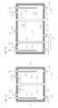
図1Aは、発明性のない電解槽Eを示す。これは、陰極室KK<12>と陽極室KA<11>を備えている。
3. Drawings 3.1 Figures 1A and 1B
1A shows a non-inventive electrolytic cell E. It comprises a cathode chamber K K <12> and an anode chamber K A <11>.
陰極室KK<12>は、内部構造IKK<122>内の陰極電極EK<123>と、入口ZKK<120>と、出口AKK<121>とを備えている。
陽極室KA<11>は、内部構造IKA<112>内の陽極電極EA<113>と、入口ZKK<110>と、出口AKA<111>とを備えている。
The cathode chamber K K <12> comprises a cathode electrode E K <123> in an internal structure I KK <122>, an inlet Z KK <120> and an outlet A KK <121>.
The anode chamber K A <11> comprises an anode electrode E A <113> in an internal structure I KA <112>, an inlet Z KK <110>, and an outlet A KA <111>.
2つの室は、二室槽Eの外壁<80>によって境界されている。内部構造IKK<122>も、ナトリウムイオンを選択的に透過するNaSICON固体電解質FA<18>のシートからなる仕切壁によって、内部構造IKA<112>から仕切られている。NaSICON固体電解質FA<18>は、二室漕Eの深さおよび高さの全体にわたって延びている。仕切壁は、2つの側SKK<161>およびSA/MK<162>を有し、その表面OKK<163>およびOA/MK<164>は、それぞれの内部構造IKK<122>またはIKA<112>と接触している。 The two chambers are bounded by the outer wall <80> of the two-chamber vessel E. The internal structure I KK <122> is also separated from the internal structure I KA <112> by a partition wall consisting of a sheet of NaSICON solid electrolyte F A <18>, which is selectively permeable to sodium ions. The NaSICON solid electrolyte F A <18> extends over the entire depth and height of the two-chamber vessel E. The partition wall has two sides S KK <161> and S A/MK <162>, whose surfaces O KK <163> and O A/MK <164> are in contact with the respective internal structure I KK <122> or I KA <112>.
pH10.5の塩化ナトリウム水溶液L3<23>が、重力方向と逆に、入口ZKA<110>を経由して内部構造IKA<112>に導入される。 An aqueous sodium chloride solution L 3 <23> with a pH of 10.5 is introduced into the internal structure I KA <112> via an inlet Z KA <110> against the direction of gravity.
ナトリウムメトキシドのメタノール溶液L2<22>が、入口ZKK<120>を経由して内部構造IKK<122>に送られる。 A methanolic solution of sodium methoxide L 2 <22> is fed via an inlet Z KK <120> to the internal structure I KK <122>.
同時に、陰極電極EK<123>と陽極電極EA<113>との間に電圧が印加される。これにより、電解質L2<22>中のメタノールが還元され、内部構造IKK<122>内にメトキシドとH2が生じる(CH3OH+e-→CH3O-+1/2H2)。同時に、ナトリウムイオンが、内部構造IKA<112>から NaSICON固体電解質FK<18>を通って、内部構造IKK<122>に拡散する。全体として、これにより、内部構造IKK<122>内のナトリウムメトキシド濃度が上昇し、L2<22>と比較してナトリウムメトキシド濃度が高いナトリウムメトキシドのメタノール溶液L1<21>が得られる。 At the same time, a voltage is applied between the cathode electrode E K <123> and the anode electrode E A <113>. This reduces the methanol in the electrolyte L 2 <22>, producing methoxide and H 2 in the internal structure I KK <122> (CH 3 OH + e - → CH 3 O - + 1/2H 2 ). At the same time, sodium ions diffuse from the internal structure I KA <112> through the NaSICON solid electrolyte F K <18> to the internal structure I KK <122>. Overall, this increases the sodium methoxide concentration in the internal structure I KK <122>, resulting in a methanol solution L 1 <21> of sodium methoxide with a higher sodium methoxide concentration compared to L 2 <22>.
内部構造IKA<112>では、塩素イオンの酸化が起こり、塩素分子が生成される(Cl-→1/2Cl2+e-)。出口AKA<111>では、NaClの含有量がL3<23>と比較して低減された水溶液L4<24>が得られる。水中の塩素ガス(Cl2)は、Cl2+H2O→HOCl+HClの反応に従って、次亜塩素酸と塩酸を生成し、さらに水分子と酸性反応を起こす。酸性は、NaSICON固体電解質FA<18>に損傷を与える。 In the internal structure I KA <112>, oxidation of chlorine ions occurs, producing chlorine molecules (Cl - →1/2Cl 2 +e - ). At the outlet A KA <111>, an aqueous solution L 4 <24> is obtained, in which the NaCl content is reduced compared to L 3 <23>. Chlorine gas (Cl 2 ) in the water produces hypochlorous acid and hydrochloric acid according to the reaction Cl 2 +H 2 O→HOCl+HCl, which further undergoes an acidic reaction with water molecules. The acidity damages the NaSICON solid electrolyte F A <18>.
図1Bは、別の発明性のない電解槽Eを示す。この三室槽Eは、陰極室KK<12>と、陽極室KA<11>と、介装中間室KMとを備えている。
陰極室KK<12>は、内部構造IKK<122>内の陰極電極EK<123>と、入口ZKK<120>と、出口AKK<121>とを備えている。
陽極室KA<11>は、内部構造IKA<112>内の陽極電極EA<113>と、入口ZKK<110>と、出口AKA<111>とを備えている。
中間室KM<13>は、内部構造IKM<132>と、入口ZKM<130>と、出口AKM<131>とを備えている。
1B shows another non-inventive electrolytic cell E. This three-compartment cell E comprises a cathode chamber K K <12>, an anode chamber K A <11> and an intermediate chamber K M.
The cathode chamber K K <12> comprises a cathode electrode E K <123> in an internal structure I KK <122>, an inlet Z KK <120> and an outlet A KK <121>.
The anode chamber K A <11> comprises an anode electrode E A <113> in an internal structure I KA <112>, an inlet Z KK <110>, and an outlet A KA <111>.
The intermediate chamber K M <13> comprises an internal structure I KM <132>, an inlet Z KM <130> and an outlet A KM <131>.
内部構造IKA<112>は、接続VAM<15>を介して内部構造IKM<132>に接続されている。 The internal structure I KA <112> is connected to the internal structure I KM <132> via a connection V AM <15>.
三室は、3室槽Eの外壁<80>によって境界されている。中間室KM<13>の内部構造IKM<132>も、ナトリウムイオンを選択的に透過するNaSICON固体電解質FA<18>のシートからなる仕切壁によって、陰極室KK<13>の内部構造IKA<122>から仕切られている。NaSICON固体電解質FA<18>は、三室槽Eの深さおよび高さの全体にわたって延びている。仕切壁は、2つの側SKK<161>およびSA/MK<162>を有し、その表面OKK<163>およびOA/MK<164>は、それぞれの内部構造IKK<122>またはIKM<132>と接触している。 The three compartments are bounded by the outer wall <80> of the three compartment cell E. The internal structure I KM <132> of the intermediate compartment K M <13> is also separated from the internal structure I KA <122> of the cathode compartment K K <13> by a partition wall consisting of a sheet of NaSICON solid electrolyte F A <18> selectively permeable to sodium ions. The NaSICON solid electrolyte F A <18> extends over the entire depth and height of the three compartment cell E. The partition wall has two sides S KK <161> and S A/MK <162>, whose surfaces O KK <163> and O A/MK <164> are in contact with the respective internal structure I KK <122> or I KM <132>.
中間室KM<13>の内部構造IKM<132>は、さらに、拡散バリアD<14>によって、陽極室KA<11>の内部構造IKA<112>から同様に仕切られている。NaSICON固体電解質FA<18>および拡散バリアD<14>は、三室槽Eの深さおよび高さの全体にわたって延びている。拡散バリアD<14>は、陽イオン交換膜(スルホン化PTFE)である。 The internal structure I KM <132> of the intermediate chamber K M <13> is further similarly separated from the internal structure I KA <112> of the anode chamber K A <11> by a diffusion barrier D <14>. The NaSICON solid electrolyte F A <18> and the diffusion barrier D <14> extend over the entire depth and height of the three-compartment cell E. The diffusion barrier D <14> is a cation exchange membrane (sulfonated PTFE).
図1Bによる実施形態では、接続VAM<15>は、電解槽Eの外側に、特にチューブまたはホースにより形成され、その材料はゴム、金属およびプラスチックから選択され得る。接続VAM<15>は、三室槽の仕切壁WA<80>の外側で、中間室KM<13>の内部構造IKM<132>から陽極室KA<11>の内部構造IKA<112>へ液体をガイドすることができる。接続VAM<15>は、中間室KM<13>の底部で電解槽Eの外壁WA<80>を貫通する出口AKM<131>を、陽極室KA<11>の底部で電解槽Eの外壁WA<80>を貫通する入口ZKA<110>に接続している。 In the embodiment according to Fig. 1B, the connection V AM <15> is formed on the outside of the electrolytic cell E, in particular by a tube or hose, the material of which can be selected from rubber, metal and plastic. The connection V AM <15> is able to guide the liquid from the internal structure I KM <132> of the intermediate chamber K M <13> to the internal structure I KA <112> of the anode chamber K A <11>, on the outside of the partition wall W A <80> of the three-compartment cell. The connection V AM <15> connects the outlet A KM <131>, which passes through the external wall W A <80> of the electrolytic cell E at the bottom of the intermediate chamber K M <13>, to the inlet Z KA <110>, which passes through the external wall W A <80> of the electrolytic cell E at the bottom of the anode chamber K A <11>.
pH10.5の塩化ナトリウム水溶液L3<23>が、重力方向に、入口ZKM<130>を経由して中間室KMの内部構造IKM<132>に導入される。中間室KM<13>からの出口AKM<131>と、陽極室KA<11>への入口ZKA<110>との間に形成された接続VAM<15>は、中間室KM<13>の内部構造IKM<132>を、陽極室KA<11>の内部構造IKA<112>に接続する。塩化ナトリウム溶液L3<23>は、この接続VAM<15>を通って、内部構造IKM<132>から内部構造IKA<112>に送られる。ナトリウムメトキシドのメタノール溶液L2<22>は、入口ZKK<120>を経由して内部構造IKK<122>に送られる。 An aqueous sodium chloride solution L 3 <23> with a pH of 10.5 is introduced in the direction of gravity via the inlet Z KM <130> into the internal structure I KM <132> of the intermediate chamber K M. A connection V AM <15> formed between the outlet A KM <131> from the intermediate chamber K M <13> and the inlet Z KA <110> into the anode chamber K A <11> connects the internal structure I KM <132> of the intermediate chamber K M <13> to the internal structure I KA <112> of the anode chamber K A <11>. The sodium chloride solution L 3 <23> is transferred from the internal structure I KM <132> to the internal structure I KA <112> through this connection V AM <15>. A methanolic solution of sodium methoxide L 2 <22> is fed via an inlet Z KK <120> to the internal structure I KK <122>.
同時に、陰極電極EK<123>と陽極電極EA<113>との間に電圧が印加される。これにより、電解質L2<22>中のメタノールが還元され、内部構造IKK<122>内にメトキシドとH2が生じる(CH3OH+e-→CH3O-+1/2H2)。同時に、ナトリウムイオンが、中間室KM<13>の内部構造IKM<132>から、NaSICON固体電解質FA<18>を通って、内部構造IKK<122>に拡散する。全体として、これにより、内部構造IKK<122>内のナトリウムメトキシド濃度が上昇し、L2<22>と比較してナトリウムメトキシド濃度が高いナトリウムメトキシドのメタノール溶液L1<21>が得られる。 At the same time, a voltage is applied between the cathode electrode E K <123> and the anode electrode E A <113>. This reduces the methanol in the electrolyte L 2 <22>, producing methoxide and H 2 in the internal structure I KK <122> (CH 3 OH + e - → CH 3 O - + 1/2H 2 ). At the same time, sodium ions diffuse from the internal structure I KM <132> of the intermediate chamber K M <13> through the NaSICON solid electrolyte F A <18> to the internal structure I KK <122>. Overall, this increases the sodium methoxide concentration in the internal structure I KK <122>, resulting in a methanol solution L 1 <21> of sodium methoxide with a higher sodium methoxide concentration compared to L 2 <22>.
内部構造IKA<112>では、塩素イオンの酸化が起こり、塩素分子が生成される(Cl-→1/2Cl2+e-)。出口AKA<111>では、NaClの含有量がL3<23>と比較して低減された水溶液L4<24>が得られる。水中の塩素ガス(Cl2)は、Cl2+H2O→HOCl+HClの反応に従って、次亜塩素酸と塩酸を形成し、さらに水分子と酸性反応を起こす。酸性は、NaSICON固体電解質FA<18>を損傷するが、三室槽内の配置により陽極室 KA<11>に限定され、電解槽E内のNaSICON固体電解質FK<18>から遠ざけられる。これにより、電解槽Eの寿命が大幅に延びる。 In the internal structure I KA <112>, oxidation of chlorine ions occurs, producing chlorine molecules (Cl - → 1/2Cl 2 + e - ). At the outlet A KA <111>, an aqueous solution L 4 <24> is obtained, in which the NaCl content is reduced compared to L 3 <23>. Chlorine gas (Cl 2 ) in the water forms hypochlorous acid and hydrochloric acid according to the reaction Cl 2 + H 2 O → HOCl + HCl, which then undergoes an acidic reaction with water molecules. The acidity, which would damage the NaSICON solid electrolyte F A <18>, is limited to the anode chamber K A <11> due to its arrangement in the three-chamber cell, and is kept away from the NaSICON solid electrolyte FK <18> in the electrolytic cell E. This significantly extends the life of the electrolytic cell E.
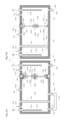
3.2 図2Aおよび図2B
図2Aは、本発明の仕切壁W<16>を示す。表面OKK<163>を有する側SKK<161>は、図面の平面にあり、表面OA/MK<164>を有する側SA/MK<162>は、図2Aでは見えないが、図面の平面の裏側にある。
3.2 Figures 2A and 2B
Figure 2A shows a partition wall W<16> of the invention, the side S KK <161> with the surface O KK <163> being in the plane of the drawing, and the side S A/MK <162> with the surface O A/MK <164> being behind the plane of the drawing, not visible in Figure 2A.
仕切壁W<16>は、枠要素R<2>の間に配置された2つのNaSICON固体電解質セラミックスFA<18>およびFB<19>を備えている。枠要素R<2>は、2つの部分R1<201>およびR2<202>を備え、それらの間にセラミックFA<18>およびFB<19>が配置されている。枠要素R<2>は、端要素RR<20>および分離要素RT<17>を形成する。分離要素RT<17>は、NaSICON固体電解質セラミックFA<18>およびFB<19>の間にあり、これらを互いに分離している。分離要素RT<17>は、図2Aおよび図2Bにおいて影付きで示される枠要素R<2>の一部である。端要素RR<20>は、図2Aおよび図2Bにおいて影無しで示される枠要素R<2>の一部である。端要素RR<20>の領域にある2つの枠部分R1<201>およびR2<202>は、8つの固定要素BR<91>によって互いに固定され、分離要素RT<17>の領域にある2つの枠部分R1<201>およびR2<202>は、1つの固定要素BT<92>によって互いに固定されている。描かれた図は、図3A~図3Cで詳細に説明されている仕切壁W<16>の断面QRR<165>およびQRT<166>を示している。QRR<165>およびQRT<166>は、2つの固体電解質セラミックスFA<18>およびFB<19>のうちの1つの領域において、表面OKK<163>に対して直角に仕切壁Wと交差している。 The partition wall W<16> comprises two NaSICON solid electrolyte ceramics F A <18> and F B <19> arranged between the frame element R<2>. The frame element R<2> comprises two parts R 1 <201> and R 2 <202>, between which the ceramics F A <18> and F B <19> are arranged. The frame element R<2> forms an end element R R <20> and a separation element R T <17>. The separation element R T <17> is between the NaSICON solid electrolyte ceramics F A <18> and F B <19> and separates them from each other. The separation element R T <17> is a part of the frame element R<2> shown shaded in Figures 2A and 2B. The end element R R <20> is a part of the frame element R<2> shown without shading in Figures 2A and 2B. The two frame parts R 1 <201> and R 2 <202> in the region of the end element R R <20> are fixed to each other by eight fixing elements B R <91>, and the two frame parts R 1 <201> and R 2 <202> in the region of the separation element R T <17> are fixed to each other by one fixing element B T <92>. The depicted diagram shows the cross sections Q RR <165> and Q RT <166> of the partition wall W <16>, which are described in detail in Figures 3A-3C. Q RR <165> and Q RT <166> intersect the partition wall W at right angles to the surface O KK <163> in the region of one of the two solid electrolyte ceramics F A <18> and F B <19>.
図2Bは、本発明の仕切壁W<16>の別の実施形態を示す。これは、仕切壁W<16>が4つのNaSICON固体電解質セラミックFA<18>、FB<19>、FC<28>、FD<29>を有し、FA<18>、FB<19>、FC<28>、FD<29>が枠部分R1<201>およびR2<202>の間に配置されている点を除いて、図2に示す実施形態に対応している。分離要素RT<17>は、十字形状である。端要素RR<20>の領域内にある2つの枠部分R1<201>およびR2<202>は、12個の固定要素BR<91>によって互いに固定され、分離要素RT<17>の領域内にある2つの枠部分R1<201>およびR2<202>は、3個の固定要素BT<92>によって互いに固定されている。表面OKK<163>を有する側SKK<161>は、図面の平面にあり、表面OA/MK<164>を有する側SA/MK<162>は、図2Bでは見えないが、図面の平面の裏側にある。 Fig. 2B shows another embodiment of the partition wall W<16> of the invention. It corresponds to the embodiment shown in Fig. 2, except that the partition wall W<16> has four NaSICON solid electrolyte ceramics F A <18>, F B <19>, F C <28>, F D <29>, F A <18>, F B <19>, F C <28>, F D <29> are arranged between the frame parts R 1 <201> and R 2 <202>. The separating element R T <17> is cross-shaped. The two frame parts R1 <201> and R2 <202> in the region of the end element R20 are fixed to each other by twelve fixing elements B91 , and the two frame parts R1 <201> and R2 <202> in the region of the separation element R17 are fixed to each other by three fixing elements B92 . The side S161 > with the surface O163 is in the drawing plane, and the side S162 > with the surface O164 is behind the drawing plane, not visible in FIG. 2B.
3.3 図3A~図3C
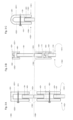
図3A~図3Cはそれぞれ、連続点線より上側で、仕切壁W<16>の端要素RR<20>の領域における、図2Aおよび図2Bに示される断面QRR<165>の詳細図を示す。図3Aおよび図3Bはまた、連続点線の下側で、仕切壁W<16>の分離要素RT<17>の領域における、図2Aおよび図2Bに示される断面QRT<166>の詳細図を示す。表面OKK<163>を有する側SKK<161>は、図3Aの右側にある。表面OA/MK<164>を有する側SA/MK<162>は、図3Aの左側にある。
3.3 Figures 3A to 3C
Figures 3A-3C each show a detailed view of the section QRR <165> shown in Figures 2A and 2B in the region of the end element R R <20> of the partition wall W<16> above the continuous dotted line. Figures 3A and 3B also show a detailed view of the section QRT <166> shown in Figures 2A and 2B below the continuous dotted line in the region of the separation element R T <17> of the partition wall W<16>. The side SKK <161> with the surface OKK <163> is on the right side of Figure 3A. The side S A/MK <162> with the surface O A/MK <164> is on the left side of Figure 3A.
図3Aでは、固体電解質セラミックFA<18>は、断面QRR<165>において、枠要素を形成する2つの枠部分R1<201>とR2<202>の間に配置されている。これらは、点線で示すように、一体形状で、または互いに独立して存在してよい。好ましくは、それらは互いに分離されている。それらは、固定要素BR<91>としてのネジによって互いに固定され、その間に固体電解質セラミックFA<18>がクランプされている。2つの枠部分R1<201>およびR2<202>と、固体電解質セラミックスFA<18>との間には、シールDi<40>が設けられることが好ましい。 In Fig. 3A, the solid electrolyte ceramic F A <18> is arranged in the cross section Q RR <165> between two frame parts R 1 <201> and R 2 <202> forming a frame element. They may be in one piece or independent of each other, as shown by the dotted lines. Preferably, they are separated from each other. They are fixed to each other by a screw as a fixing element B R <91>, between which the solid electrolyte ceramic F A <18> is clamped. Preferably, a seal Di <40> is provided between the two frame parts R 1 <201> and R 2 <202> and the solid electrolyte ceramic F A <18>.
断面QRT<166>では、分離要素RT<17>を構成する2つの枠部分R1<201>およびR2<202>の間に、2つの固体電解質セラミックスFA<18>およびFB<19>が配置されている。それらは、固定要素BT<92>としてのネジによって互いに固定され、その間に固体電解質セラミックスFA<18>およびFB<19>がクランプされ、好ましくはシールDi<40>を備えている。 In the cross section QRT <166>, two solid electrolyte ceramics F A <18> and F B <19> are arranged between two frame parts R1 <201> and R2<202> constituting the separating element R T <17>. They are fixed to each other by a screw as a fixing element B T <92>, between which the solid electrolyte ceramics F A <18> and F B <19> are clamped, and preferably equipped with a seal Di<40>.
図3Bは、2つの断面QRR<165>およびQRT<166>それぞれのさらなる実施形態を示す。これは、2つの固定要素BR<91>およびBT<92>がフックBH<93>により形成される点を除いて、図3Aに示す実施形態に対応している。これらのフックは、各枠部分R1<201>またはR2<202>と一緒になった(本明細書で示すような)一体形状であってもよく、またはそれらに接合されていてもよい。それらは互いに係合し、2つの枠部分R1<201>およびR2<202>を互いに固定することができる。 Figure 3B shows a further embodiment of the two cross sections QRR <165> and QRT <166> respectively. It corresponds to the embodiment shown in Figure 3A, except that the two fixing elements B R <91> and B T <92> are formed by hooks BH <93>. These hooks may be of integral shape (as shown here) with the respective frame part R1 <201> or R2 <202> or may be joined to them. They can engage with each other and fix the two frame parts R1 <201> and R2 <202> to each other.
図3Cは、断面QRR<165>のさらなる実施形態を示す。これは、端要素RR<20>が丸い角を形成する点を除いて、図3Aに示す実施形態に対応している。 Figure 3C shows a further embodiment of a cross section QRR <165>, which corresponds to the embodiment shown in Figure 3A, except that the end elements RRR <20> form rounded corners.
3.4 図4Aおよび図4B
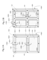
図4Aおよび図4Bはそれぞれ、本発明の第2の態様による電解槽E<1>を示す。これらはそれぞれ、仕切壁W<16>が陰極室KK<12>の内部構造IKK<122>を、陽極室KA<11>の内部構造IKA<112>から分離している点を除いて、図1Aに示す電解槽に対応している。仕切壁は、図2Aまたは図2Bに示されている仕切壁である。
3.4 Figures 4A and 4B
Figures 4A and 4B each show an electrolytic cell E<1> according to a second aspect of the invention, which corresponds to the electrolytic cell shown in Figure 1A, except that a partition wall W<16> separates the internal structure I KK <122> of the cathode chamber K K <12> from the internal structure I KA <112> of the anode chamber K A <11>. The partition wall is the partition wall shown in Figure 2A or 2B.
この場合、図4Aによる実施形態では、固定要素BR<91>およびBT<92>としてネジが使用されている。仕切壁W<16>の端要素RR<20>の領域の断面QRR<165>と、仕切壁W<16>の分離要素RT<17>の領域の断面QRT<166>とは、いずれの場合も、図3Aで説明されている通りである。 In this case, in the embodiment according to Fig. 4A, screws are used as fixing elements B R <91> and B T <92>. The cross sections Q RR <165> in the region of the end element R R <20> of the partition wall W<16> and the cross sections Q RT <166> in the region of the separating element R T <17> of the partition wall W<16> are in each case as described in Fig. 3A.
図4Bによる実施形態では、相互に係合するフックBH<93>が、固定要素BR<91>およびBT<92>として使用されている。仕切壁W<16>の端要素RR<20>の領域の断面QRR<165>と、仕切壁W<16>の分離要素RT<17>の領域の断面QRT<166>とは、いずれの場合も、図3Bで説明されている通りである。 In the embodiment according to Fig. 4B, mutually engaging hooks BH <93> are used as fastening elements BR <91> and BT <92>. The cross sections QRR <165> in the region of the end element RRR <20> of the partition wall W<16> and the cross sections QRT <166> in the region of the separating element RTT <17> of the partition wall W<16> are in each case as described in Fig. 3B.
3.5 図5Aおよび図5B
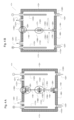
図5Aは、本発明の第2の態様による電解槽E1を示す。これは、仕切壁W<16>が陰極室KK<12>の内部構造IKK<122>を、中間室KM<13の内部構造IKM<132>から分離している点を除いて、図1Bに示す電解槽に対応している。仕切壁W<16>は、図2Aまたは図2Bに示されている仕切壁である。この場合、図4Aによる実施形態では、ねじが固定要素BR<91>およびBT<92>として使用されている。仕切壁W<16>の端要素RR<20>の領域の断面QRR<165>と、仕切壁Wの分離要素RT<17>の領域の断面QRT<166>とは、いずれの場合も、図3Aで説明されている通りである。
3.5 Figures 5A and 5B
Fig. 5A shows an electrolytic cell E1 according to a second aspect of the invention. It corresponds to the electrolytic cell shown in Fig. 1B, except that a partition wall W<16> separates the internal structure I KK <122> of the cathode chamber K K <12> from the internal structure I KM <132> of the intermediate chamber K M <13. The partition wall W<16> is the partition wall shown in Fig. 2A or 2B. In this case, in the embodiment according to Fig. 4A, screws are used as fastening elements B R <91> and B T <92>. The cross section Q RR <165> in the region of the end element R R <20> of the partition wall W<16> and the cross section Q RT <166> in the region of the separating element R T <17> of the partition wall W are in each case as described in Fig. 3A.
図5Bは、本発明の第2の態様による電解槽E1を示す。これは、図5Aに示す電解槽E<1>に対応しているが、次の2つの相違点がある。
相違点1
中間室KM<13>の内部構造IKM<132>から陽極室KA<11>の内部構造IKA<112>への接続VAM<15>は、電解槽E<1>の外側に形成されておらず、むしろ、拡散バリアD<14>の穿孔を通って内側に形成されている。この穿孔は、拡散バリアD<14>内に形成されてもよく、または拡散バリアD<14>の製造始めから拡散バリアD<14>内にすでに存在していてもよい(例えば、濾過布または金属ウィーブのような織物の場合)。
相違点2
図5Bによる実施形態では、相互に係合するフックBH<93>が固定要素BR<91>およびBT<92>として使用されている。仕切壁W<16>の端要素RR<20>の領域の断面QRR<165>と、仕切壁W<16>の分離要素RT<17>の領域の断面QRT<166>とは、いずれの場合も、図3Bで説明されている通りである。
Figure 5B shows an electrolytic cell E1 according to a second embodiment of the invention, which corresponds to the electrolytic cell E<1> shown in Figure 5A, but with two differences:
The connection V AM <15> from the internal structure I KM <132> of the intermediate chamber K M <13> to the internal structure I KA <112> of the anode chamber K A <11> is not made on the outside of the electrolytic cell E<1>, but rather on the inside through perforations in the diffusion barrier D<14>. The perforations may be made in the diffusion barrier D<14> or may already be present in the diffusion barrier D<14> from the beginning of its manufacture (for example in the case of fabrics such as filter cloths or metal weaves).
In the embodiment according to Fig. 5B, mutually engaging hooks BH <93> are used as fastening elements BR <91> and BT <92>. The cross sections QRR <165> in the region of the end elements RRR <20> of the partition wall W<16> and the cross sections QRT <166> in the region of the separating elements RTT <17> of the partition wall W<16> are in each case as described in Fig. 3B.
分離要素RT<17>は、図6Aおよび図6Bにおいて影付きで示される枠要素R<2>の一部である。 The separation element R T <17> is part of the frame element R<2>, which is shown shaded in FIGS. 6A and 6B.
3.6 図6Aおよび図6B
図6Aは、本発明の仕切壁W<16>のさらなる実施形態を、(左側に)表面OKK<163>を有する側SKK<161>の上面図で示す。そして、矢印の方向に見た曲線状クランプの詳細を示す側面図である。
3.6 Figures 6A and 6B
Fig. 6A shows a further embodiment of a partition wall W<16> of the invention in a top view of the side S KK <161> with the surface O KK <163> (on the left) and in a side view showing a detail of the curved clamp in the direction of the arrow.
これは、4つのNaSICON固体電解質セラミックFA<18>、FB<19>、FC<28>およびFD<29>で構成され、それらは、枠要素R<2>の両半分R1<201>およびR2<202>の間に配置されている。枠要素R<2>は、端要素RR<20>と分離要素RT<17>とを形成する。分離要素RT<17>は、十字形状であり、NaSICON固体電解質セラミックスFA<18>、FB<19>、FC<28>およびFD<29>の間に位置し、これらを互いに分離している。分離要素RT<17>は、図6Aおよび図6Bにおいて影付きで示される枠要素R<2>の一部である。端要素RR<20>は、図6Aおよび図6Bにおいて影無しで示される枠要素R<2>の一部である。端要素RR<20>の領域にある2つの枠部分R1<201>およびR2<202>は、固定要素BR<91>によって互いに固定されている。そして、分離要素RT<17>の領域にある2つの枠部分R1<201>およびR2<202>は、固定要素BT<92>によって互いに固定されている。それらは、必要に応じて、ヒンジ<50>により互いに接続されてもよい。いずれの場合も、シールDi<40>としてのゴムリングが、各固体電解質セラミックFA<18>、FB<19>、FC<28>およびFD<29>と、2つの枠部分R1<201>およびR2<202>と、の間に設けられることが好ましい。シールDi<40>として機能するリングは、図6Aの左側の正面図において点線の輪郭線で示されている。 It is composed of four NaSICON solid electrolyte ceramics F A <18>, F B <19>, F C <28> and F D <29>, which are arranged between the two halves R 1 <201> and R 2 <202> of the frame element R<2>. The frame element R<2> forms an end element R R <20> and a separating element R T <17>. The separating element R T <17> is cross-shaped and is located between the NaSICON solid electrolyte ceramics F A <18>, F B <19>, F C <28> and F D <29>, separating them from each other. The separating element R T <17> is part of the frame element R<2> shown shaded in Figures 6A and 6B. The end element R R <20> is part of the frame element R<2> shown without shading in Figures 6A and 6B. The two frame parts R 1 <201> and R 2 <202> in the region of the end element R R <20> are fixed to each other by the fixing element B R <91>. And the two frame parts R 1 <201> and R 2 <202> in the region of the separation element R T <17> are fixed to each other by the fixing element B T <92>. They may be connected to each other by a hinge <50>, if necessary. In either case, a rubber ring as a seal Di <40> is preferably provided between each solid electrolyte ceramic F A <18>, F B <19>, F C <28> and F D <29> and the two frame parts R 1 <201> and R 2 <202>. The ring functioning as the seal Di <40> is shown in dotted outline in the front view on the left of FIG. 6A.
図6Bは、本発明の仕切壁W<16>のさらなる実施形態を示す。これは、9個のNaSICON固体電解質セラミックFA<18>、FB<19>、FC<28>、FD<29>、FE<30>、FF<31>、FG<32>、FH<33>、FI<34>を含む点を除いて、図6A記載の実施形態に対応している。さらに、枠要素R<2>は、それぞれが穴<61>を備えた4つの膨らみ<60>(「ウサギ耳」)をさらに有し、これにより、仕切壁を、適切な設計で例えば陰極室KK<12>に固定することができる。 Fig. 6B shows a further embodiment of the partition wall W<16> of the invention, which corresponds to the embodiment according to Fig. 6A, except that it comprises nine NaSICON solid electrolyte ceramics F A <18>, F B <19>, F C <28>, F D <29>, F E <30>, F F <31>, F G <32>, F H <33>, F I <34>. Furthermore, the frame element R<2> further has four bulges <60>("rabbitears"), each with a hole <61>, by means of which the partition wall can be fixed, for example, to the cathode chamber K K <12> with a suitable design.
4.発明の詳細な説明
4.1 仕切壁W
本発明は、第1の態様において、仕切壁Wに関する。これは、電解槽、特に電解槽Eの仕切壁として特に適している。
4. Detailed Description of the Invention 4.1 Partition Wall W
The present invention relates in a first aspect to a partition wall W. This is particularly suitable as a partition wall of an electrolytic cell, in particular an electrolytic cell E.
したがって、一態様では、本発明は、仕切壁Wを備える電解槽、特に仕切壁Wを備える電解槽Eにも関する。 Thus, in one aspect, the present invention also relates to an electrolytic cell comprising a partition wall W, in particular an electrolytic cell E comprising a partition wall W.
仕切壁Wは、分離要素RTによって互いに分離された、少なくとも2つのアルカリ金属陽イオン伝導性固体電解質セラミックス(「アルカリ金属陽イオン伝導性固体電解質セラミックス」を以下「ASC」と略記する)FAおよびFBを備えている。
The partition wall W comprises at least two alkali metal cation conductive solid electrolyte ceramics (hereinafter abbreviated as "ASC") F 1 A and
仕切壁Wは、互いに対向する2つの側SKKおよびSA/MKを備え、これは、側SA/MKが側SKKの反対側であることを意味する(その逆も同様)。2つの側SKKおよびSA/MKは特に、互いに全く平行な平面を有している。
それ以外は、仕切壁Wの幾何学的形状は、さらなる制約を受けず、特にその仕切壁Wが使用される電解槽Eの断面に適合させることができる。例えば、直方体形状で長方形の断面を有してもよく、または円錐または円柱形状で円形の断面を有してもよい。
必要に応じて、仕切壁Wは、丸い角または膨らみを備えた直方体の形状でもよく、その膨らみには穴が設けられていてもよい。仕切壁Wは、仕切壁Wを電解槽に固定することができるか、あるいは仕切壁Wの2つの枠部分R1およびR2を互いに固定することができる膨らみ(「ウサギ耳」)を有している。
The partition wall W has two sides SKK and S A/MK opposite each other, which means that the side S A/MK is opposite the side SKK (and vice versa). The two sides SKK and S A/MK in particular have planes which are entirely parallel to each other.
Otherwise, the geometric shape of the partition W is not subject to further constraints and can in particular be adapted to the cross-section of the electrolytic cell E in which it is used. For example, it may be cuboidal in shape and have a rectangular cross-section, or conical or cylindrical in shape and have a circular cross-section.
If desired, the partition W may be in the shape of a rectangular parallelepiped with rounded corners or bulges, which may be provided with holes, and has bulges ("rabbit ears") by means of which the partition W can be fixed to the electrolytic cell or by means of which the two frame parts R1 and R2 of the partition W can be fixed to each other.
仕切壁Wの側SKKは、面OKKを有し、仕切壁Wの側SA/MKは面OA/MKを有する。 The side S KK of the partition W has a face O KK and the side S A/MK of the partition W has a face O A/MK .
仕切壁Wは、枠要素Rを含んでいる。これは、2つの対向する部分、好ましくは二つ割りのR1およびR2で構成され、その間には、少なくとも2つのアルカリ金属陽イオン伝導性固体セラミックFAおよびFBが配置されている。R1は、面OKKから直接接触可能であり、R2は、面OA/MKから直接接触可能である。 The partition wall W comprises a frame element R. It is made up of two opposing parts, preferably halves R1 and R2 , between which at least two alkali metal cation conducting solid ceramics F A and F B are arranged. R1 is directly accessible from the face O KK and R2 is directly accessible from the face O A/MK .
枠要素Rは、枠要素RRおよび分離要素RTを形成し、枠要素RRは、面OKKおよびOA/MKを境界し、好ましくは完全に取り囲んでいる。そして、枠要素RTは、仕切壁Wに含まれるアルカリ金属陽イオン伝導性固体電解質セラミックスの間に位置し、これらを互いに分離している。したがって、仕切壁Wに含まれるアルカリ金属陽イオン伝導性固体電解質セラミックスは、面OKKおよび面OA/MKの両方から直接接触可能である。
The frame element R forms a frame element R 1 R and a
特徴「仕切壁」は、仕切壁Wが液密であることを意味する。これは、ASCと枠要素Rとが隙間なく隣接していることを意味する。したがって、枠要素Rと仕切壁に含まれるASCとの間に隙間は存在せず、隙間を通って水溶液、アルコール溶液、アルコールまたは水がSKK側からSA/MK側に、またはその逆に流れることはない。 The feature "partition wall" means that the partition wall W is liquid-tight. This means that the ASC and the frame element R are adjacent to each other without any gap. Therefore, there is no gap between the frame element R and the ASC contained in the partition wall, and no aqueous solution, alcohol solution, alcohol or water can flow through the gap from the S KK side to the S A/MK side or vice versa.
仕切壁Wに含まれるアルカリ金属陽イオン伝導性固体電解質セラミックスと各部分R1またはR2とが直接接触可能な面を介して対向する側が二対以上ある場合、本明細書の文脈においてSKKおよびSA/MKとして表される一対の対向する側は、最大の表面積OKKおよびOA/MKを含む対であることが好ましい。二対の対向する側に含まれる表面積が同じである場合、当業者であれば、面OKKおよびOA/MKを有するSKKおよびSA/MKとして1つの対を選択することができる。 When there are two or more pairs of opposing sides through a surface where the alkali metal cation conductive solid electrolyte ceramic contained in the partition wall W and each part R1 or R2 can directly contact each other, the pair of opposing sides represented as S KK and S A/MK in the context of this specification is preferably a pair including the largest surface areas O KK and O A /MK. When the surface areas included in the two pairs of opposing sides are the same, a person skilled in the art can select one pair as S KK and S A /MK having surfaces O KK and O A/MK .
仕切壁Wに含まれるアルカリ金属陽イオン伝導性固体電解質セラミックスと各部分R1またはR2とが直接接触可能な面を介して対向する側が二対以上存在する仕切壁Wのうち、対向する側のそれぞれの対に含まれる表面積が異なる仕切壁Wが好ましい。この場合、本明細書の文脈においてSKKおよびSA/MKと呼ばれる対向する側の対は、最大表面積のOKKおよびOA/MKを含むものである。 Among the partition walls W having two or more pairs of opposing sides through a surface where the alkali metal cation conductive solid electrolyte ceramic contained in the partition wall W and each portion R1 or R2 can directly contact each other, the partition walls W having different surface areas in each pair of opposing sides are preferred. In this case, the pairs of opposing sides referred to as S KK and S A/MK in the context of this specification include the O KK and O A/MK with the largest surface areas.
本発明の第1の態様による仕切壁Wには、仕切壁Wが2つ以上のASC、例えば4個、9個または12個のASCを備える実施形態も含まれる。 The partition wall W according to the first aspect of the present invention also includes embodiments in which the partition wall W comprises two or more ASCs, for example four, nine or twelve ASCs.
仕切壁Wでは、仕切壁Wに含まれるすべてのASCは、枠要素Rの分離要素RTによって互いに分離されており、これは、ASCが別のASCに直接隣接しないこと、すなわち、間に枠要素Rが存在しないことを意味する。 In a partition wall W, all ASCs contained in the partition wall W are separated from each other by separation elements R T of a frame element R, which means that no ASC is directly adjacent to another ASC, i.e. there is no frame element R in between.
仕切壁Wは、仕切壁Wに含まれるASCが、表面OKKおよび表面OA/MKの両方から直接接触可能であることをさらに特徴とする。 Partition W is further characterized in that the ASC contained in partition W is directly accessible from both surface O KK and surface O A/MK .
仕切壁Wに含まれるASCに関して「直接接触可能」とは、表面OKKおよびOA/MKの一部が、仕切壁Wに含まれるASCの表面により形成されていることを意味し、仕切壁Wに含まれるASCが、2つの表面OKKおよびOA/MKから直接アクセス可能であることを意味する。そのため、例えば、水溶液、アルコール溶液、アルコールまたは水により、2つの表面OKKおよびOA/MKにおいてそれらを濡らすことができる。 "Directly accessible" with respect to the ASCs contained in the partition W means that the surfaces O KK and O A/MK are partly formed by the surfaces of the ASCs contained in the partition W, and that the ASCs contained in the partition W are directly accessible from the two surfaces O KK and O A/MK , so that they can be wetted at the two surfaces O KK and O A/MK by, for example, an aqueous solution, an alcoholic solution, alcohol or water.
仕切壁W内のASCの配置に関してこれが意味するのは、仕切壁Wに含まれる各ASCについて、側SKKの表面OKKから、それぞれのASCを完全に通過して、側SA/MKの表面OA/MKに至るルートが存在するということである。 What this means with regard to the arrangement of the ASCs within the partition W is that for each ASC contained in the partition W, there exists a route from the surface O KK of the side S KK , completely through the respective ASC, to the surface O A /MK of the side S A/MK.
2つの枠要素R1およびR2は、表面OKKおよびOA/MKから直接接触可能である。 The two frame elements R1 and R2 are directly accessible from the surfaces OKK and OA/MK .
仕切壁Wに含まれる枠部分R1に関して「直接接触可能」とは、表面OKKの一部が、枠部分R1の表面により形成されていることを意味し、枠部分R1は表面OKKから直接アクセス可能であることを意味する。そのため、例えば、水溶液、アルコール溶液、アルコールまたは水により、表面OKKにおいてそれを濡らすことができる。 "Directly accessible" with respect to the frame portion R1 included in the partition wall W means that a part of the surface OKK is formed by the surface of the frame portion R1 and that the frame portion R1 is directly accessible from the surface OKK , so that it can be wetted at the surface OKK by, for example, an aqueous solution, an alcoholic solution, alcohol or water.
仕切壁Wに含まれる枠部分R2に関して「直接接触可能」とは、表面OA/MKの一部が、枠部分R2の表面によって形成されており、枠部分R2が表面OA/MKから直接アクセス可能であることを意味する。そのため、例えば、水溶液、アルコール溶液、アルコールまたは水により、表面OA/MKにおいてそれを濡らすことができる。 "Directly accessible" with respect to the frame portion R2 included in the partition wall W means that a part of the surface O A/MK is formed by the surface of the frame portion R2 and the frame portion R2 is directly accessible from the surface O A/ MK, so that it can be wetted at the surface O A/MK by, for example, an aqueous solution, an alcoholic solution, alcohol or water.
特に仕切壁W内の枠要素Rの配置に関してこれが意味するのは、側SKKの表面OKKから、R1部分を通過し、次いでR2部分を通過し(場合により、シールDiを通過し)、ASCは通過せずに、側SA/MKの表面OA/MKに至るルートが存在するということである。 What this means in particular with regard to the arrangement of the frame element R in the partition W is that there is a route from the surface O KK of the side S KK , through the R 1 portion, then through the R 2 portion (possibly through the seal Di) to the surface O A /MK of the side S A/MK, without passing through the ASC.
本発明の第1の態様における仕切壁Wの好ましい実施形態では、表面OKKの50%~95%、より好ましくは60%~90%、さらにより好ましくは70%~85%が、仕切壁Wに含まれるASCにより形成され、表面OKKの残りの部分は、さらにより好ましくは、枠部分R1により形成される。 In a preferred embodiment of the partition wall W in the first aspect of the present invention, 50% to 95%, more preferably 60% to 90%, even more preferably 70% to 85% of the surface OKK is formed by the ASC contained in the partition wall W, and the remaining portion of the surface OKK is even more preferably formed by the frame portion R1 .
本発明の第1の態様における仕切壁Wの好ましい実施形態では、表面OA/MKの50%~95%、より好ましくは60%~90%、さらにより好ましくは70%~85%も、仕切壁Wに含まれるASCにより形成され、表面OA/MKの残りの部分は、さらにより好ましくは、枠部分R2により形成される。 In a preferred embodiment of the partition W in the first aspect of the present invention, 50% to 95%, more preferably 60% to 90%, even more preferably 70% to 85% of the surface O A/MK is formed by the ASC contained in the partition W, and the remaining portion of the surface O A/MK is even more preferably formed by the frame portion R2 .
好ましい実施形態では、仕切壁W、特に枠要素RとASCとの間の仕切壁Wは、シールDi(例えば、図3A、図3Bおよび図3Cに示す)を備えている。これにより、特に効率的な方法で、仕切壁Wが液密であることが確保される。 シールDiは、当業者により、各ASCまたは各枠要素Rについて選択され得る。 In a preferred embodiment, the partitions W, in particular the partitions W between the frame elements R and the ASC, are provided with seals Di (for example as shown in Figures 3A, 3B and 3C). This ensures in a particularly efficient manner that the partitions W are liquid-tight. The seals Di can be selected for each ASC or each frame element R by the skilled person.
シールDiは、特に、エラストマー、接着剤、好ましくはエラストマーからなる群から選択される材料を含んでいる。 The seal Di comprises in particular a material selected from the group consisting of elastomers, adhesives, preferably elastomers.
有用なエラストマーは、特に、ゴム、好ましくはエチレン-プロピレン-ジエンゴム(「EPDM」)、フルオロポリマーゴム(「FPM」)、パーフルオロポリマーゴム(「FFPM」)、またはアクリロニトリル-ブタジエンゴム(「NBR」)である。 Useful elastomers are, in particular, rubbers, preferably ethylene-propylene-diene rubbers ("EPDM"), fluoropolymer rubbers ("FPM"), perfluoropolymer rubbers ("FFPM"), or acrylonitrile-butadiene rubbers ("NBR").
シールDiは、2つの枠部分R1およびR2が互いに固定され、ASCが2つの枠部分R1およびR2の間に配置される際に、圧縮されるように選択されることが好ましい。これにより、仕切壁Wの完全性がさらに高まる。 The seal Di is preferably selected such that it is compressed when the two frame parts R1 and R2 are fixed together and the ASC is placed between the two frame parts R1 and R2 , which further enhances the integrity of the partition wall W.
好ましい実施形態では、仕切壁Wは、少なくとも4個のASCであるFA、FB、FCおよびFDを備え、さらにより好ましくは、ちょうど4個のASCであるFA、FB、FCおよびFDを備えている。 In a preferred embodiment, the partition wall W comprises at least four ASCs F A , F B , F C and F D , and even more preferably comprises exactly four ASCs F A , F B , F C and F D.
さらに好ましい実施形態では、仕切壁Wは、少なくとも9個のASCであるFA、FB、FC、FD、FE、FF、FG、FHおよびFIを備え、さらにより好ましくは、ちょうど9個のASCであるFA、FB、FC、FD、FE、FF、FG、FHおよびFIを備えている。 In a further preferred embodiment , the partition W comprises at least nine ASCs F , ...
さらに好ましい実施形態では、仕切壁Wは、少なくとも12個のASCであるFA、FB、FC、FD、FE、FF、FG、FH、FI、FJ、FKおよびFLを備え、さらにより好ましくは、ちょうど12個のASCであるFA、FB、FC、FD、FE、FF、FG、FH、FI、FJ、FKおよびFLを備えている。 In a further preferred embodiment, the partition wall W comprises at least twelve ASCs F A , F B , F C , F D , F E , F F , F G , F H , F I , F J , F K and F L , and even more preferably comprises exactly twelve ASCs F A , F B , F C , F D , F E , F F , F G , F H , F I , F J , F K and F L.
仕切壁W内で互いに並んだ少なくとも2個のASCの本発明の配置は、従来技術の電解槽内の従来の仕切壁と比較して、電解槽の作動中に温度変動が生じた場合に、ASCにさらなる拡散方向をもたらす。従来技術の電解槽では、仕切壁として機能するNaSICONシートは、電解槽の外壁または固体プラスチックフレームによって枠組みされている。この方法では、NaSICON内での膨張の際に発生する機械的応力を分散させることはできず、セラミックの破損につながる可能性がある。 The inventive arrangement of at least two ASCs next to each other in the partition wall W provides an additional diffusion direction for the ASCs when temperature fluctuations occur during operation of the cell, compared to conventional partition walls in prior art cells, where the NaSICON sheet acting as the partition wall is framed by the outer wall of the cell or by a solid plastic frame. In this way, mechanical stresses occurring during expansion in the NaSICON cannot be distributed and may lead to fracture of the ceramic.
対照的に、本発明の第1の態様における仕切壁W内の個々のASCは、分離要素RTに隣接している。表面OKKおよびOA/MKの端にあるASCの場合は、枠要素RRにも隣接している。これは有利な効果をもたらし、どちらもASC の長期安定性を高める。
-各ASCは、さらに利用可能な自由度、すなわち、ASCが膨張可能な面積を有している。z方向の拡張(すなわち、仕切壁Wの水平面に対して直角にセラミックシートの厚さを越える膨張)だけでなく、xおよび/またはy方向の膨張、すなわち、仕切壁Wの水平面内の水平および垂直方向の膨張も可能である。例えば固体シートとしてのASCが電解槽の断面に広がり、電解槽の固体壁に隣接する場合には、この膨張の方向は存在しないか、または少なくとも大幅に制限される。
-1個のASCのみを含む等しいサイズの仕切壁と比較して、複数の小さな ASCに分割すると、より小さなASC内で発生する応力も絶対的に小さくなり、より迅速に消散できるため、ASCの破損につながる応力がそれほど早く蓄積できないという効果がある。
In contrast, the individual ASCs in the partition wall W in the first aspect of the invention are adjacent to the separation element RT and, in the case of the ASCs at the ends of the surfaces OKK and OA/MK , also adjacent to the frame element RR , which has advantageous effects, both of which increase the long-term stability of the ASCs.
- each ASC has an additional degree of freedom available, i.e. the area over which it can expand: not only in the z-direction (i.e. expansion perpendicular to the horizontal plane of the partition W beyond the thickness of the ceramic sheet), but also in the x- and/or y-direction, i.e. horizontal and vertical expansion in the horizontal plane of the partition W. If the ASC, for example as a solid sheet, spans the cross-section of the electrolytic cell and abuts the solid wall of the electrolytic cell, this direction of expansion does not exist or is at least strongly limited.
- Compared to an equal sized partition containing only one ASC, division into multiple smaller ASCs has the effect that the stresses generated within the smaller ASCs are also smaller in absolute terms and can dissipate more quickly, so that stresses that lead to ASC failure do not build up as quickly.
その結果、仕切壁W内の「分割された」ASCについては、1枚のシートを使用する場合と比較して、破損の傾向が明らかに減少する。 As a result, the tendency for breakage to occur is significantly reduced for the "split" ASC within the partition wall W compared to using a single sheet.
4.1.1 枠要素R
枠要素Rは、2つの対向する部分R1およびR2を備え、その間には、仕切壁Wに含まれる2つのアルカリ金属陽イオン伝導性固体セラミックスFAおよびFBが配置されている。この配置は、当業者によく知られたすべての方法で行うことができる。特定の実施形態では、2つの部分R1およびR2は、好ましくは枠要素R内でASCをさらに安定させるシールDiを使用して、それらの間にASCをクランプする。別の好ましい実施形態では、ASCは、2つの枠部分R1およびR2に接着されている。この目的に使用される接着剤KIは、電解条件下で安定である、当業者によく知られているすべての接着剤であり得る。好ましいKIには、エポキシ樹脂、フェノール樹脂から選択される少なくとも1つの物質が含まれる。
4.1.1 Frame element R
The frame element R comprises two opposing parts R1 and R2 between which are arranged two alkali metal cation conducting solid ceramics F A and F B contained in a partition wall W. This arrangement can be carried out in all manners well known to those skilled in the art. In a particular embodiment, the two parts R1 and R2 clamp the ASC between them, preferably using a seal Di which further stabilizes the ASC in the frame element R. In another preferred embodiment, the ASC is glued to the two frame parts R1 and R2 . The adhesive KI used for this purpose can be all adhesives well known to those skilled in the art that are stable under electrolytic conditions. Preferred KI include at least one substance selected from epoxy resins, phenolic resins.
仕切壁Wは、枠要素Rの2つの部分R1およびR2を開閉できるヒンジを備えていてもよい。 The partition wall W may be provided with a hinge that allows the two parts R1 and R2 of the frame element R to be opened and closed.
枠要素Rは、特に、プラスチック、ガラス、木材からなる群から選択される材料を含んでいる。より好ましくは、枠要素Rは、プラスチックを含んでいる。
さらにより好ましくは、そのプラスチックは、ポリプロピレン、ポリスチレン、ポリ塩化ビニルからなる群から選択されるものである。
The frame element R comprises in particular a material selected from the group consisting of plastic, glass and wood, more preferably the frame element R comprises plastic.
Even more preferably, the plastic is selected from the group consisting of polypropylene, polystyrene, polyvinyl chloride.
好ましい実施形態では、シールDiは、枠要素Rと、仕切壁Wに含まれるASCとの間に設けられる。これにより、仕切壁Wの液密性が向上する。 In a preferred embodiment, the seal Di is provided between the frame element R and the ASC included in the partition wall W. This improves the liquid-tightness of the partition wall W.
枠要素Rは、端要素RRおよび分離要素RTを形成する。 The frame element R forms an end element R 1 R and a separating element R 1 T.
4.1.1.1 分離要素RT
分離要素RTは、少なくとも2つのASCの間に位置し、これらを互いに分離する枠要素Rの領域を指す。枠要素Rの領域としての分離要素RTは、2つの部分R1およびR2によって形成される。
4.1.1.1 Separation element R T
The separation element R_T refers to a region of the frame element R that is located between at least two ASCs and separates them from each other. The separation element R_T as a region of the frame element R is divided into two parts R_1 and R_2 . is formed by.
枠要素Rによって形成される適切な分離要素RTは、それによってそれぞれのASCを互い分離して配置することができるすべての物体である。ASCは、電解槽E内で陰極室を隣接する中間室または陽極室から液密に仕切る仕切壁Wの機能を損なわないように、分離要素RTに隙間なく隣接している。 Suitable separating elements R_T formed by the frame element R are all objects by means of which the respective ASCs can be arranged separated from one another. The ASCs adjoin the separating elements R_T with no gaps so as not to impair the function of the partition wall W which separates the cathode chamber from the adjacent intermediate or anode chambers in a liquid-tight manner in the electrolytic cell E.
分離要素RTの形状は、特に仕切壁Wに含まれるASCの数および形状に応じて、当業者によって選択されてよい。 The shape of the separation element R T may be selected by the person skilled in the art, depending in particular on the number and shape of the ASCs to be included in the partition W.
例えば、仕切壁Wが2個または3個のASCを備える場合、これらは、分離要素RTとしてASC間に配置されたランドによってそれぞれ分離され得る(例えば、図2Aを参照)。 For example, if a partition wall W comprises two or three ASCs, these may be separated by lands disposed between the ASCs as separation elements RT , respectively (see, for example, FIG. 2A).
仕切壁WがASCを4つ以上備える場合、これらは、十字形状(図2Bおよび図6Aを参照)または格子形状(図6Bを参照)の分離要素RTによって分離され得る。 If the partition wall W comprises more than three ASCs, these may be separated by cross-shaped (see Figs. 2B and 6A) or lattice-shaped (see Fig. 6B) separating elements R T.
仕切壁Wが少なくとも4個のASCを備えることが好ましい。そして、三次元すべてをASCの熱膨張/収縮に完全に利用できるため、分離要素RTは十字形状または格子形状であることがさらに好ましい。 It is preferred that the partition wall W comprises at least four ASCs, and it is even more preferred that the separating elements RT are cross-shaped or lattice-shaped, since all three dimensions are fully available for the thermal expansion/contraction of the ASCs.
分離要素RTは特に、各ASCが分離要素内に嵌合またはクランプできるように形成されている。これは、仕切壁Wの製造において、対応する方法ですでに実施されていてもよい。 The separating element R_T is in particular designed so that the respective ASC can be fitted or clamped therein, this may already have been achieved in a corresponding manner in the production of the partition wall W.
分離要素RTは、プラスチック、ガラスおよび木材からなる群から選択される材料を含むことが好ましい。より好ましくは、分離要素RTはプラスチックを含んでいる。
さらにより好ましくは、そのプラスチックは、ポリプロピレン、ポリスチレン、ポリ塩化ビニル(「PVC」)からなる群から選択されるものである。PVCには、後塩素化ポリ塩化ビニル(「PVC-C」)も含まれる。
Preferably, the separating element R T comprises a material selected from the group consisting of plastic, glass and wood, more preferably, the separating element R T comprises plastic.
Even more preferably, the plastic is selected from the group consisting of polypropylene, polystyrene, and polyvinyl chloride ("PVC"), which also includes post-chlorinated polyvinyl chloride ("PVC-C").
4.1.1.2 端要素RR
枠要素Rは、分離要素RTを形成するだけでなく、端要素RRも形成する。枠要素Rの領としての端要素RRは、2つの部分R1およびR2によって形成される。 端要素RR(分離要素RTとは異なる)は、仕切壁Wに含まれるアルカリ金属陽イオン伝導性固体電解質セラミックスの間に配置されていない枠要素Rの領域であり、すなわち、アルカリ金属陽イオン伝導性固体電解質セラミックスを互いに分離するものではない。
4.1.1.2 End element R R
The frame element R not only forms a separating element R 1 T but also an
端要素RRは、面OKKおよびOA/MKを少なくとも部分的に、好ましくは完全に境界する。これが意味するのは、より具体的には、端要素RRは、面OKKおよびOA/MKを少なくとも部分的に、好ましくは完全に取り囲んでいるということである。 The end element R 1 R at least partially, preferably completely, bounds the faces O KK and O A/MK , which means more specifically that the end element R 1 R at least partially, preferably completely, surrounds the faces O KK and O A/MK .
端要素RRは、面OKKおよびOA/MKの一部である場合もあれば、そうでない場合もある。端要素RRは、面OKKおよびOA/MKの一部であることが好ましい。
The
端要素RRは、特に、面OKKおよびOA/MKから直接接触可能であるか、または直接接触可能ではない。
The
端要素RRは、面OKKおよびOA/MKから直接接触可能であることが好ましい。 この好ましい実施形態では、R1の一部としての端要素RRは、面OKKから直接接触可能であり、R2の一部としての端要素RRは、面OA/MKから直接接触可能である。
It is preferred that the end element R 1 R is directly accessible from the faces O KK and O AA/MK . In this preferred embodiment, the
仕切壁Wに含まれる端要素RRに関して「直接接触可能ではない」とは、端要素RRが、専ら、仕切壁Wの側SKKおよびSA/MKではない側の表面の少なくとも一部として形成されることを意味する。より具体的には、この場合の端要素RRは、仕切壁Wの側SKKおよびSA/MKではない側の表面積の少なくとも1%、より好ましくは少なくとも25%、より好ましくは少なくとも50%、さらにより好ましくは100%を形成する。
"Not directly accessible" with respect to an
仕切壁Wに含まれる枠要素RRに関して「直接接触可能」とは、表面OKKの一部が枠要素RRの表面によって形成されていることを意味し、枠要素RRが表面OKKから直接アクセス可能であることを意味する。そのため、例えば水溶液、アルコール溶液、アルコールまたは水により、それを表面OKKで濡らすことができる。
"Directly accessible" in relation to a
仕切壁Wに含まれる枠要素RRに関して「直接接触可能」とは、表面OA/MKの一部が枠要素RRの表面によって形成されていることでもあり、枠要素RRが直表面OA/MKから直接アクセス可能であることを意味する。そのため、例えば、水溶液、アルコール溶液、アルコールまたは水により、それを表面OA/MKで濡らすことができる。これが仕切壁W内の端要素RRの配置に関して意味するのは、側SKKの表面OKKから、端要素RRを完全に通って、側SA/MKの表面OA/MKに至るルートが存在することである。
"Directly accessible" in relation to a
これには、以下の実施形態が含まれる。
‐表面OKKおよびOA/MKの端の一部が端要素RRによって形成されている。
‐(図2A、図2B、図6A、図6Bに示すように)表面OKKおよびOA/MKの端は、端要素RRによって完全に形成されている。
This includes the following embodiments:
- the ends of the surfaces O KK and O A/MK are partly formed by end elements R R.
the ends of the surfaces O KK and O A/MK are completely formed by end elements R RR (as shown in FIGS. 2A, 2B, 6A and 6B);
端要素RRは、仕切壁Wの側SKKおよびSA/MKではない側の表面の少なくとも一部としてさらに形成され得る。より具体的には、端要素RRは、仕切壁Wの側SKKおよびSA/MKではない側の表面積の少なくとも1%、より好ましくは少なくとも25%、より好ましくは少なくとも50%、さらにより好ましくは100%を形成する。 The end element R 1 R may further be formed as at least a part of the surface of the side not S KK and S A/MK of the partition W. More specifically, the end element R 1 R forms at least 1%, more preferably at least 25%, more preferably at least 50%, even more preferably 100% of the surface area of the side not S KK and S A/MK of the partition W.
例えば、図2Aおよび図2Bは、端要素RRが、仕切壁Wの側SKKおよびSA/MKではない側の表面を完全に形成する実施形態を示している。 For example, Figures 2A and 2B show an embodiment in which the end element R 1 R completely forms the surface of the partition wall W on the sides that are not sides S KK and S A/MK .
端要素RRは、プラスチック、ガラス、木材からなる群から選択される材料を含むことが好ましい。より好ましくは、端要素RRはプラスチックを含む。
さらにより好ましくは、そのプラスチックは、ポリプロピレン、ポリスチレン、ポリ塩化ビニル(「PVC」)からなる群から選択されるものである。PVCには、後塩素化ポリ塩化ビニル(「PVC-C」)も含まれる。
Preferably, the
Even more preferably, the plastic is selected from the group consisting of polypropylene, polystyrene, and polyvinyl chloride ("PVC"), which also includes post-chlorinated polyvinyl chloride ("PVC-C").
さらに好ましい実施形態では、端要素RRおよび分離要素RTは、同じ材料を含み、両方ともプラスチックを含むことがさらにより好ましく、そのプラスチックは、さらにより好ましくはポリプロピレン、ポリスチレン、ポリ塩化ビニル、PVC-Cから選択される。
In a further preferred embodiment, the end element R 1 R and the
好ましい実施形態では、分離要素RTの少なくとも一部は、枠要素RRの少なくとも一部と一体に形成されている。これがより具体的に意味するのは、分離要素RTの少なくとも一部が端要素RRと合体しているということである。
In a preferred embodiment, at least a portion of the separating
端要素RRの実施形態は、電解槽Eの外壁の一部として機能するというさらなる利点を有する。仕切壁Wのこの部分は、各内部構造IKK、IKAまたはIKM内の溶液と接触しない。したがって、仕切壁Wのこの部分を固体電解質セラミックで形成するのは無駄である。さらに、外壁の間にクランプされているか、または外壁の一部を形成している仕切壁Wの部分は、脆い固体電解質セラミックでは耐えられないであろう力にさらされる。したがって、代わりに、耐破壊性の、より安価な材料が枠要素Rに選ばれる。 The embodiment of the end element R R has the further advantage that it serves as part of the outer wall of the electrolytic cell E. This part of the partition W is not in contact with the solution in the respective internal structures I KK , I KA or I KM . It would therefore be wasteful to form this part of the partition W from solid electrolyte ceramic. Moreover, the parts of the partition W which are clamped between the outer walls or form part of them would be subjected to forces which the brittle solid electrolyte ceramic would not be able to withstand. Therefore, instead, a fracture-resistant, cheaper material is chosen for the frame element R.
4.1.2 固定要素BRおよびBT
本発明の第1の態様における仕切壁Wは、R1およびR2が端要素RRにおいて少なくとも1つの固定要素BRによって互いに固定され、R1およびR2が分離要素RTにおいて少なくとも1つの固定要素BTによって互いに固定されていることを特徴とする。
4.1.2 Fixation elements B R and B T
The partition wall W in the first aspect of the invention is characterized in that R1 and R2 are fixed to each other at the end element R2R by at least one fixing element B3R , and R1 and R2 are fixed to each other at the separation element R3T by at least one fixing element B4T .
これに関連して、「端要素RRにおいて」とは、「端要素RRの領域において」の意味である。
In this context, "at the
これに関連して、「分離要素RTにおいて」とは、「分離要素RTの領域において」の意味である。 In this context, "at the separation element R T " means "in the region of the separation element R T ".
適切な固定要素BRおよびBTは、2つの枠部分R1およびR2を互いに固定するための当業者によく知られたすべての手段である。
Suitable fixing elements B 1 R and
これらの固定要素BRおよびBTは、特に、ヒンジ、クランプ、釘、ネジ、フックから選択され、好ましくはネジ、フックから選択され、、最も好ましくはフックである。 These fixing elements B 1 R and B 1 T are in particular chosen from hinges, clamps, nails, screws, hooks, preferably chosen from screws, hooks, most preferably hooks.
固定要素BRおよびBTは、当業者によく知られた材料から作製され得る。
それらは、プラスチック、ガラス、木材からなる群から選択される材料を含むことが好ましい。プラスチックが特に好ましい。
さらにより好ましくは、そのプラスチックは、ポリプロピレン、ポリスチレン、ポリ塩化ビニル、PVC-Cからなる群から選択されるものである。
The anchoring elements B 1 R and
They preferably comprise a material selected from the group consisting of plastic, glass, wood, with plastic being particularly preferred.
Even more preferably, the plastic is selected from the group consisting of polypropylene, polystyrene, polyvinyl chloride, PVC-C.
さらにより好ましくは、少なくとも1つの固定要素BRおよび少なくとも1つの固定要素BTはそれぞれ、相互に係合するフックBHの形態である。互いに固定された状態で、これらのフックは、特に仕切壁Wをまたぐことになる。
Even more preferably, the at least one
この目的のために、BTとして、相互に対向する対のフックBHが、有利には、分離要素RTの領域において、2つの枠部分R1およびR2の相互に対面する側にそれぞれ形成され、これらは、枠部分R1およびR2の間のASCの配置に応じて、互いに、好ましくは可逆的に係合する。この実施形態では、枠要素RRが表面OKKおよびOA/MKから直接接触可能でなければならないことが明らかである。 For this purpose, as B T , mutually opposing pairs of hooks B H are advantageously formed on the mutually facing sides of the two frame parts R 1 and R 2 , respectively, in the region of the separating element R T , which engage with one another, preferably reversibly, depending on the arrangement of the ASC between the frame parts R 1 and R 2. It is clear that in this embodiment, the frame element R R must be directly accessible from the surfaces O KK and O A/MK .
この目的のために、BRとして、相互に対向する対のフックBHが、有利には、端要素RRの領域において、2つの枠部分R1およびR2の相互に対面する側にそれぞれ形成され、これらは、枠部分R1およびR2の間のASCの配置に応じて、可逆的に互いに係合する。 For this purpose, as B R , mutually opposing pairs of hooks B H are advantageously formed on mutually facing sides of the two frame parts R 1 and R 2 , respectively, in the region of the end element R R , which reversibly engage with one another depending on the arrangement of the ASC between the frame parts R 1 and R 2 .
「2つの枠部分R1およびR2の相互に対面する側」とは、R1の場合には、その面が面OKKから直接接触可能ではない2つの枠部分の側を指し、R2の場合には、その面が面OA/MKから直接接触可能ではない2つの枠部分の側を指す。これらは、特に、仕切壁W内のASCおよび/またはシールDiと接する面R1およびR2である。 "Mutually facing sides of the two frame parts R1 and R2 " refers in the case of R1 to the side of the two frame parts whose face is not directly accessible from the face O KK , and in the case of R2 to the side of the two frame parts whose face is not directly accessible from the face O A/MK . These are in particular the faces R1 and R2 which are in contact with the ASC and/or the seal Di in the partition wall W.
固定手段BRおよびBT、特にフックは、部品R1およびR2の少なくとも1つと一体形状であることが好ましい(図3B)。 The fastening means B R and B T , in particular the hooks, are preferably of integral form with at least one of the parts R 1 and R 2 (FIG. 3B).
別の好ましい実施形態では、少なくとも1つの固定要素BRおよび少なくとも1つの固定要素BTはそれぞれ、相互に係合するフックBHの形態である。
In another preferred embodiment, the at least one fixing
好ましい実施形態では、フックBHは、ASCが枠部分R1およびR2の間に配置される場合に係合し、そのため枠部分R1およびR2を互いに固定するように、分離要素RTの領域および端要素RRの領域において枠部分R1およびR2の両方に形成される。さらにより好ましくは、これは可逆的であり、フックBHは互いに取り外すことができることを意味する。これは、例えば、フックが相互に移動可能であるように設計されることにより達成することができる。 In a preferred embodiment, the hooks BH are formed on both the frame parts R1 and R2 in the region of the separation element R1T and in the region of the end element R2R , such that when the ASC is placed between the frame parts R1 and R2 they engage and thus fix the frame parts R1 and R2 to one another. Even more preferably, this is reversible, meaning that the hooks BH can be detached from one another. This can be achieved, for example, by designing the hooks to be mutually movable.
固定手段BRおよびBTを端要素RRおよび分離要素RTの両方に取り付けることにより、驚くべきことだが、仕切壁Wの安定性が向上する。端要素RRの領域だけでなく分離要素RTの領域にも固定手段を使用することにより、外側の角だけでなく、枠要素Rの領域全体に圧縮力を導入することが可能となる。
The attachment of the fastening means B 1 R and B 1 T to both the end element R 1 R and the separating
4.1.3 アルカリ金属陽イオン伝導性固体電解質セラミックス(「ASC」)
仕切壁Wに含まれる有用なアルカリ金属陽イオン伝導性固体電解質セラミックFA、FB等は、それを通過させて陽イオン、特にアルカリ金属陽イオン、さらにより好ましくはナトリウム陽イオンをSA/MK側からSKK側へ輸送することができるすべての固体電解質である。このような固体電解質は、当業者に知られており、例えば、ドイツ特許出願公開第10 2015 013 155号明細書、国際公開第2012/048032号パンフレットの段落[0035]、[0039]、[0040]、米国特許出願公開第2010/0044242号明細書の段落[0040]、[0041]、ドイツ特許第10360758号明細書の段落[014]~[025]に記載されている。これらは、NaSICON、LiSICON、KSICONの名前で市販されている。ナトリウムイオン伝導性固体電解質が好ましく、これがNaSICON構造を有することがさらに好ましい。本発明に従って使用可能なNaSICON構造は、例えば、N.Anantharamulu、K.Koteswara Rao、G.Rambabu、B.Vijaya Kumar、Velchuri Radha、M.VithalのJ Mater Sci2011、46、2821~2837頁にも記載されている。
4.1.3 Alkali Metal Cation Conducting Solid Electrolyte Ceramics ("ASC")
Useful alkali metal cation-conducting solid electrolyte ceramics F A , F B etc. contained in the partition wall W are all solid electrolytes through which cations, in particular alkali metal cations, and even more preferably sodium cations, can be transported from the S A/MK side to the S KK side. Such solid electrolytes are known to the person skilled in the art and are described, for example, in DE 10 2015 013 155 A1, WO 2012/048032 A1, paragraphs [0035], [0039], [0040], US 2010/0044242 A1, paragraphs [0040], [0041] and DE 10360758 A1, paragraphs [014] to [025]. They are commercially available under the names NaSICON, LiSICON, KSICON. Sodium ion conducting solid electrolytes are preferred, more preferably having the NaSICON structure, which can be used according to the invention, for example, is also described in N. Anantharamulu, K. Koteswara Rao, G. Rambabu, B. Vijaya Kumar, Velchuri Radha, M. Vithal, J Mater Sci 2011, 46, 2821-2837.
仕切壁Wの好ましい実施形態では、仕切壁Wに含まれるアルカリ金属陽イオン伝導性固体セラミックは、独立して、式MI
1+2w+x-y+zMII
wMIII
xZrIV
2-w-x-yMV
y(SiO4)z(PO4)3-zのNaSICON構造を有する。
式中、MIは、Na+、Li+から選択され、好ましくはNa+である。
MIIは、二価の金属陽イオンであり、好ましくはMg2+、Ca2+、Sr2+、Ba2+、Co2+、Ni2+から選択され、より好ましくはCo2+、Ni2+から選択される。
MIIIは、三価の金属陽イオンであり、好ましくはAl3+、Ga3+、Sc3+、La3+、Y3+、Gd3+、Sm3+、Lu3+、Fe3+、Cr3+から選択され、より好ましくはSc3+、La3+、Y3+、Gd3+、Sm3+から選択され、特に好ましくはSc3+、Y3+、La3+から選択される。
MVは、5価の金属陽イオンであり、好ましくはV5+、Nb5+、Ta5+から選択される。
In a preferred embodiment of the partition wall W, the alkali metal cation conducting solid ceramics contained in the partition wall W independently have the NaSICON structure of the formula M I 1+2w+x - y + z M II w M III x Zr IV 2 - w - x - y M V y (SiO 4 ) z (PO 4 ) 3 - z .
In the formula, M I is selected from Na + , Li + , and is preferably Na + .
M II is a divalent metal cation, preferably selected from Mg 2+ , Ca 2+ , Sr 2+ , Ba 2+ , Co 2+ , Ni 2+ , more preferably selected from Co 2+ , Ni 2+ .
M III is a trivalent metal cation, preferably selected from Al 3+ , Ga 3+ , Sc 3+ , La 3+ , Y 3+ , Gd 3+ , Sm 3+ , Lu 3+ , Fe 3+ , and Cr 3+ , more preferably selected from Sc 3+ , La 3+ , Y 3+ , Gd 3+ , and Sm 3+ , and particularly preferably selected from Sc 3+ , Y 3+ , and La 3+ .
M V is a pentavalent metal cation, preferably selected from V 5+ , Nb 5+ , Ta 5+ .
ローマ数字のI、II、III、IV、Vは、各金属陽イオンが存在する酸化数を示している。 The Roman numerals I, II, III, IV, and V indicate the oxidation number in which each metal cation exists.
w、x、y、zは実数で、0≦x<2、0≦y<2、0≦w<2、0≦z< 3であり、w、x、y、zは、1+2w+x-y+z≧0かつ2-w-x-y ≧0となるように選択される。 w, x, y, z are real numbers with 0≦x<2, 0≦y<2, 0≦w<2, 0≦z<3, and w, x, y, z are selected such that 1+2w+x-y+z≧0 and 2-w-x-y≧0.
本発明によれば、さらにより好ましくは、NaSICON構造は、式Na(1+v)Zr2SivP(3-v)O12の構造を有する。式中、vは、0≦v≦3の実数である。最も好ましくは、v=2.4である。 Even more preferably, according to the invention, the NaSICON structure has the structure of formula Na (1+v) Zr2SivP (3 - v) O12 , where v is a real number with 0≦v≦3. Most preferably, v=2.4.
本発明の第1の態様による仕切壁Wの好ましい実施形態では、仕切壁Wに含まれるASCは、同一の構造を有する。 In a preferred embodiment of the partition wall W according to the first aspect of the present invention, the ASCs included in the partition wall W have the same structure.
4.1.4 仕切壁Wの製造
仕切壁Wは、当業者に知られている方法により製造することができる。
4.1.4 Manufacturing of the Partition Wall W The partition wall W can be manufactured by methods known to those skilled in the art.
例えば、仕切壁Wに含まれるASCが、必要に応じてシールを備える適切な鋳造型に挿入され、枠要素Rが液体プラスチックにより鋳造され、次いで固化させるために放置されてよい(射出成形法)。固化の過程で、これがASCを取り囲む。固定要素BTおよびBRは、枠要素R上に適切な形状により1つの鋳造物として設けられてよい(そして、枠要素Rと一体形状となる)。この実施形態では、相互に係合するフックBHが固定手段として特に適している。
For example, the ASC contained in the partition W may be inserted into a suitable casting mould, optionally equipped with seals, and the frame element R may be cast with liquid plastic and then left to solidify (injection moulding process), during which it surrounds the ASC. The fixing elements B 1 T and
あるいは、枠要素R、または枠部品R1およびR2は、別々に鋳造される。固定要素BTおよびBRは、枠要素R上に適切な形状により1つの鋳造物として設けられてよい(そして、枠要素Rと一体形状となる)。この実施形態では、相互に係合するフックBHが固定手段として特に適している。 Alternatively, the frame element R, or the frame parts R1 and R2 , are cast separately. The fixing elements B1T and B1R may be provided as one casting with suitable shape on the frame element R (and are of one-piece shape with the frame element R). In this embodiment, mutually engaging hooks B1H are particularly suitable as fixing means.
あるいは、必要に応じてシールDiを備えるASCを、枠部品R1およびR2の間に配置することができ、次いで、固定要素BTおよびBRを取り付けることができる。この目的に適した例は、枠部品R1およびR2の適切な切り欠きに打ち込まれ、これらを互いに固定するネジまたは釘である。 Alternatively, the ASC, optionally equipped with the seal Di, can be placed between the frame parts R1 and R2 and then the fixing elements B1T and B2R can be attached. Examples suitable for this purpose are screws or nails which are driven into suitable cutouts in the frame parts R1 and R2 and fasten them to one another.
4.2 電解槽E
本発明の第1の態様の仕切壁Wは、電解槽Eの仕切壁として適している。
したがって、第2の態様では、本発明は、
‐少なくとも1つの入口ZKAと、少なくとも1つの出口AKAと、陽極電極EAを備える内部構造IKAとを有する少なくとも1つの陽極室KA、
‐少なくとも1つの入口ZKKと、少なくとも1つの出口AKKと、陰極電極EKを備える内部構造IKKとを有する少なくとも1つの陰極室KK、および
‐必要に応じて、少なくとも1つの入口ZKMと、少なくとも1つの出口AKMと、内部構造IKMとを有する少なくとも1つの介装中間室KM
を含む電解槽Eであり、
IKAとIKMは、拡散バリアDによって互いに区切られ、AKMは、接続VAMによって入口ZKAに接続され、接続VAMを経由してIKMからIKAへ液体を送ることができ、
電解槽Eが中間室KMを備えていない場合、IKAとIKKは、本発明の第1の態様による仕切壁Wによって互いに区切られ、
電解槽Eが少なくとも1つの中間室KMを備えている場合、IKKとIKMは、本発明の第1の態様による仕切壁Wによって互いに区切られ、
仕切壁W<16>に含まれるアルカリ金属陽イオン伝導性固体電解質セラミックス、特に分離要素RTは、表面OKKを介してSKK側の内部構造IKKに直接接触し、かつ
電解槽Eが中間室KMを備えていない場合、仕切壁Wに含まれるアルカリ金属陽イオン伝導性固体電解質セラミックス、特に枠要素Rは、表面OA/MKを介してSA/MK側の内部構造IKAに直接接触し、
電解槽Eが少なくとも1つの中間室KMを備えている場合、仕切壁Wに含まれるアルカリ金属陽イオン伝導性固体電解質セラミックス、特に枠要素Rは、表面OA/MKを介してSA/MK側の内部構造IKMに直接接触している、電解槽E
に関する。
4.2 Electrolytic cell E
The partition wall W of the first embodiment of the present invention is suitable as a partition wall of an electrolytic cell E.
Thus, in a second aspect, the present invention provides a method for producing a medicament for the treatment of a pulmonary arthritis, comprising:
at least one anode chamber K A having at least one inlet Z KA , at least one outlet A KA and an internal structure I KA equipped with an anode electrode E A ,
at least one cathode chamber K K having at least one inlet Z KK , at least one outlet A KK and an internal structure I KK with a cathode electrode E K , and optionally at least one intermediate intermediate chamber K M having at least one inlet Z KM , at least one outlet A KM and an internal structure I KM .
an electrolytic cell E comprising
I K and I K are separated from each other by a diffusion barrier D, A K is connected to an inlet Z K by a connection V AM , and liquids can be conveyed from I K to I K via the connection V AM ;
If the electrolytic cell E does not comprise an intermediate chamber KM , IKA and IKK are separated from each other by a partition wall W according to the first aspect of the invention,
If the electrolytic cell E comprises at least one intermediate chamber KM , IKK and IKM are separated from one another by a partition wall W according to the first aspect of the invention,
the alkali metal cation conductive solid electrolyte ceramics contained in the partition wall W<16>, in particular the separating element R T , are in direct contact with the internal structure I KK on the S KK side via the surface O KK , and if the electrolytic cell E does not have an intermediate chamber K M , the alkali metal cation conductive solid electrolyte ceramics contained in the partition wall W, in particular the frame element R, are in direct contact with the internal structure I KA on the S A/MK side via the surface O A/MK ,
If the electrolytic cell E comprises at least one intermediate chamber KM , the alkali metal cation conductive solid electrolyte ceramics contained in the partition wall W, in particular the frame element R, are in direct contact with the internal structure IKM on the S A/MK side via the surface O A/MK .
Regarding.
本発明の第2の態様における電解槽Eは、少なくとも1つの陽極室KAと、少なくとも1つの陰極室KKと、必要に応じて少なくとも1つの介装中間室KMとを備える。これには、2つ以上の陽極室KAおよび/または陰極室KKおよび/または中間室KMを有する電解槽Eも含まれる。これらの室がモジュールの形で互いに連結しているこのような電解槽は、例えば、東ドイツ特許出願公開第258143号明細書および米国特許出願公開第2006/0226022号明細書に記載されている。 The electrolytic cell E in the second embodiment of the invention comprises at least one anode chamber K A , at least one cathode chamber K K and, if necessary, at least one intermediate chamber K M. This also includes electrolytic cells E having two or more anode chambers K A and/or cathode chambers K K and/or intermediate chambers K M. Such electrolytic cells, in which the chambers are connected to one another in the form of modules, are described, for example, in DD-A-258143 and US-A-2006/0226022.
本発明の第2の態様における電解槽Eは、好ましい実施形態では、陽極室KAと、陰極室KKと、必要に応じて介装中間室KMとを備える。 In a preferred embodiment, the electrolytic cell E in the second aspect of the present invention comprises an anode chamber K 1 A , a cathode chamber K 2 K and, if necessary, an intermediate chamber K 1 M.
電解槽Eは、通常、外壁WAを有する。外壁WAは、特に、鋼、好ましくはゴム引き鋼、プラスチック、特にTelene(登録商標)(熱硬化性ポリジシクロペンタジエン)、PVC(ポリ塩化ビニル)、PVC-C(後塩素化ポリ塩化ビニル)、PVDF(ポリフッ化ビニリデン)からなる群から選択される材料から作られる。WAは、特に、入口と出口のために穴があけられていてよい。WA内には、少なくとも1つの陽極室KAと、少なくとも1つの陰極室KKと、電解槽Eが1つの中間室KMを備える実施形態では少なくとも1つの介装中間室KMとがある。 The electrolytic cell E typically has an outer wall W A. The outer wall W A is made in particular from a material selected from the group consisting of steel, preferably rubberized steel, plastic, in particular Telene® (thermosetting polydicyclopentadiene), PVC (polyvinyl chloride), PVC-C (post-chlorinated polyvinyl chloride), PVDF (polyvinylidene fluoride). W A may in particular be perforated for inlets and outlets. Within W A there is at least one anode chamber K A , at least one cathode chamber K K and, in the embodiment in which the electrolytic cell E comprises one intermediate chamber K M , at least one intermediate chamber K M.
4.2.1 陰極室KK
陰極室KKは、少なくとも1つの入口ZKKと、少なくとも1つの出口AKKと、陰極電極EK備える内部構造IKKとを有する。
4.2.1 Cathode chamber K K
The cathode chamber KK has at least one inlet ZKK , at least one outlet AKK and an internal structure IKK with a cathode electrode EK .
電解槽Eが中間室KMを備えていない場合、陰極室KKの内部構造IKKは、本発明の第1の態様の仕切壁Wによって、陽極室KAの内部構造IKAから区切られる。電解槽Eが少なくとも1つの中間室KMを備えている場合、陰極室KKの内部構造IKKは、本発明の第1の態様の仕切壁Wによって、中間室KMの内部構造IKMから区切られる。 If the electrolytic cell E does not comprise an intermediate chamber KM , the internal structure IKK of the cathode chamber KK is separated from the internal structure IKA of the anode chamber KA by the partition wall W of the first aspect of the invention. If the electrolytic cell E comprises at least one intermediate chamber KM , the internal structure IKK of the cathode chamber KK is separated from the internal structure IKM of the intermediate chamber KM by the partition wall W of the first aspect of the invention.
4.2.1.1 陰極電極EK
陰極室KKは、陰極電極EKを備える内部構造IKKを備えている。この種の有用な陰極電極EKは、本発明の第3の態様における本発明による方法の条件下で安定である、当業者によく知られたすべての電極である。これらは、特に、国際公開第2014/008410号パンフレットの段落[025]またはドイツ特許出願公開第10360758号明細書の段落[030]に記載されている。この電極EKは、メッシュウール、三次元マトリックス構造、および「ボール」からなる群から選択され得る。陰極電極EKは、特に、鋼、ニッケル、銅、白金、白金メッキ金属、パラジウム、炭素担持パラジウム、チタンからなる群から選択される材料を含む。好ましくは、EKはニッケルを含む。
4.2.1.1 Cathode electrode EK
The cathode chamber K K is provided with an internal structure I K K with a cathode electrode E K. A useful cathode electrode E K of this kind is stable under the conditions of the method according to the invention in the third aspect of the invention. These are in particular the electrodes described in paragraph [025] of WO 2014/008410 or in paragraph [030] of DE 103 60 758 A1, which are well known to the person skilled in the art. This electrode EK can be selected from the group consisting of a mesh wool, a three-dimensional matrix structure and a "ball". The cathode electrode EK can be made of, in particular, steel, nickel, copper, platinum, platinum-plated metal, It comprises a material selected from the group consisting of palladium, palladium on carbon, and titanium.Preferably, EK comprises nickel.
中間室KMを備える、本発明の第2の態様による電解槽Eの実施形態では、中間室KMは、陽極室KAと陰極室KKとの間にある。 In an embodiment of the electrolyser E according to the second aspect of the invention comprising an intermediate chamber KM , the intermediate chamber KM is between the anode chamber KA and the cathode chamber KK .
4.2.1.2 入口ZKKおよび出口AKK
陰極室KKは、入口ZKKおよび出口AKKも含んでいる。これにより、陰極室KKの内部構造IKKへの液体、例えば溶液L2の添加と、その中に存在する液体、例えば溶液L1の除去とが可能になる。入口ZKKおよび出口AKKは、液体が陰極室KKの内部構造IKKを通って流れるときに、液体が陰極電極EKと接触するように、陰極室KKに取り付けられている。これは、アルカリ金属アルコキシドXORのアルコールROH溶液である溶液L2が陰極室KKの内部構造IKKを通って送られる際、本発明の第3の態様における本発明による方法の実施において、出口AKKで溶液L1が得られるための前提条件である。
4.2.1.2 Inlet ZKK and outlet AKK
The cathode chamber K K also contains an inlet Z KK and an outlet A KK , which allow the addition of a liquid, for example solution L 2 , to the internal structure I KK of the cathode chamber K K and the removal of a liquid, for example solution L 1 , present therein. The inlet Z KK and the outlet A KK are attached to the cathode chamber K K in such a way that the liquid comes into contact with the cathode electrode E K when it flows through the internal structure I KK of the cathode chamber K K. This is a prerequisite for the
入口ZKKおよび出口AKKは、当業者に知られている方法、例えば、液体の導入および排出を簡素化する外壁穴および対応する接続部(バルブ)によって、電解槽Eに取り付けられてよい。 The inlet Z KK and outlet A KK may be attached to the electrolytic cell E in a manner known to those skilled in the art, for example by means of external wall holes and corresponding connections (valves) which simplify the introduction and discharge of liquids.
4.2.2 陽極室KA
陽極室KAは、少なくとも1つの入口ZKAと、少なくとも1つの出口AKAと、陽極電極EAを備える内部構造IKAを有する。
4.2.2 Anode chamber K A
The anode chamber K A has at least one inlet Z KA , at least one outlet A KA and an internal structure I KA with an anode electrode E A.
電解槽Eが中間室KMを備えている場合、陽極室KAの内部構造IKAは、拡散バリアDによって中間室KMの内部構造IKMから区切られる。 If the electrolytic cell E comprises an intermediate chamber KM , the internal structure IKA of the anode chamber KA is separated from the internal structure IKM of the intermediate chamber KM by a diffusion barrier D.
電解槽Eが中間室KMを備えていない場合、陽極室Kの内部構造IKAは、仕切壁Wによって陰極室KKの内部構造IKKから区切られる。 If the electrolytic cell E does not comprise an intermediate chamber KM , the internal structure IKA of the anode chamber K is separated from the internal structure IKK of the cathode chamber KK by a partition wall W.
4.2.2.1 陽極電極EA
陽極室KAは、陽極電極EAを備える内部構造IKAを備える。この種の有用な陽極電極EAは、本発明の第3の態様における本発明による方法の条件下で安定である、当業者によく知られているすべての電極である。これらは、特に、国際公開第2014/008410A号パンフレットの段落[024]またはドイツ特許出願公開第10360758号明細書の段落[031]に記載されている。この電極EAは、1つの層から構成されていてもよく、またはそれぞれが穿孔もしくは膨張していてよい互いに平行な複数の平面層から構成されていてもよい。陽極電極EAは、特に、酸化ルテニウム、酸化イリジウム、ニッケル、コバルト、タングステン酸ニッケル、チタン酸ニッケル、チタンまたはKovar(登録商標)(各成分が鉄:54質量%、ニッケル:29質量%、コバルト:17質量%であることが好ましい鉄・ニッケル・コバルト合金)などの担体上に担持された特に白金など貴金属からなる群から選択される材料を含む。さらに可能な陽極材料は、特に、ステンレス鋼、鉛、グラファイト、炭化タングステン、二ホウ化チタンである。好ましくは、陽極電極EAは、酸化ルテニウム/酸化イリジウムでコーティングされたチタン陽極を含む(RuO2+IrO2/Ti)。
4.2.2.1 Anode electrode E A
The anode chamber K A comprises an internal structure I K A with an anode electrode E A. A useful anode electrode E A of this kind is stable under the conditions of the method according to the invention in the third aspect of the invention, These are all electrodes that are well known to the person skilled in the art. These are in particular those described in paragraph [024] of WO 2014/008410 A or in paragraph [031] of DE 103 60 758 A1. This electrode EA may consist of one layer or of several parallel planar layers, each of which may be perforated or expanded. The anode electrode EA is In particular, ruthenium oxide, iridium oxide, nickel, cobalt, nickel tungstate, nickel titanate, titanium or Kovar® (each component is 54% by weight of iron, 29% by weight of nickel, and 17% by weight of cobalt) The material comprises a material selected from the group consisting of precious metals, particularly platinum, supported on a support such as an iron-nickel-cobalt alloy, preferably an iron-nickel-cobalt alloy. Further possible anode materials are, inter alia, stainless steel, lead, graphite, tungsten carbide, titanium diboride. Preferably, the anode electrode E A comprises a titanium anode coated with ruthenium oxide/iridium oxide (RuO 2 + IrO2 /Ti).
4.2.2.2 入口ZKAおよび出口AKA
陽極室KKは、入口ZKAおよび出口AKAも含んでいる。これにより、陰極室KAの内部構造IKAへの液体、例えば溶液L3の添加と、その中に存在する液体、例えば溶液L4の除去とが可能になる。入口ZKAおよび出口AKAは、液体が陽極室KAの内部構造IKAを通って流れるときに、液体が陽極電極EAと接触するように、陽極室KAに取り付けられている。これは、塩Sの溶液L3が陰極室KAの内部構造IKAを通って送られるとき、本発明の第3の態様における本発明による方法の実施において、出口AKAで溶液L4が得られるための前提条件である。
4.2.2.2 Inlet Z KA and outlet A KA
The anode chamber K K also contains an inlet Z KA and an outlet A KA , which allow the addition of a liquid, for example solution L 3 , to the internal structure I KA of the cathode chamber K A and the removal of a liquid, for example solution L 4 , present therein. The inlet Z KA and the outlet A KA are attached to the anode chamber K A such that, when the liquid flows through the internal structure I KA of the anode chamber K A , it comes into contact with the anode electrode E A. This is a prerequisite for obtaining a solution L 4 at the outlet A KA in the implementation of the method according to the invention in the third aspect of the invention, when a solution L 3 of salt S is fed through the internal structure I KA of the cathode chamber K A.
入口ZKAおよび出口AKAは、当業者に知られている方法、例えば、液体の導入および排出を簡素化する外壁穴および対応する接続部(バルブ)によって、電解槽Eに取り付けられてよい。電解槽Eが中間室KMを備えている特定の実施形態では、入口ZKAはまた、電解槽内に、例えば拡散バリアDの穿孔の形で存在してもよい。 The inlets Z KA and the outlets A KA may be attached to the electrolytic cell E in a manner known to those skilled in the art, for example by means of external wall holes and corresponding connections (valves) that simplify the introduction and discharge of liquids. In certain embodiments in which the electrolytic cell E comprises an intermediate chamber KM , the inlets Z KA may also be present in the electrolytic cell, for example in the form of perforations in the diffusion barrier D.
4.2.3 任意選択の中間室KM
本発明の第2の態様における電解槽Eは、中間室KMを有することが好ましい。 任意選択の中間室KMは、陰極室KKと陽極室KAとの間に位置している。それは、少なくとも1つの入口ZKMと、少なくとも1つの出口AKMと、内部構造IKMとを備える。
4.2.3 Optional Intermediate Chamber KM
The electrolytic cell E in the second aspect of the invention preferably has an intermediate chamber KM . The optional intermediate chamber KM is located between the cathode chamber KK and the anode chamber KA . It comprises at least one inlet ZKM , at least one outlet AKM and an internal structure IKM .
電解槽Eが中間室KMを備えている場合、陽極室KAの内部構造IKAは、拡散バリアDによって中間室KMの内部構造IKMから区切られている。次いで、AKMは、液体が接続VAMを通ってIKMからIKAへ誘導され得るように、接続VAMによって入口ZKAにも接続されている。 If the electrolytic cell E comprises an intermediate chamber KM , the internal structure IKA of the anode chamber KA is separated from the internal structure IKM of the intermediate chamber KM by a diffusion barrier D. AKM is then also connected to an inlet ZKA by a connection VAM , so that liquid can be led from IKM to IKA through the connection VAM .
4.2.3.1 拡散バリアD
任意選択の中間室KMの内部構造IKMは、拡散バリアDによって陽極室KAの内部構造IKAから区切られ、仕切壁Wによって陰極室KKの内部構造IKKから区切られている。
4.2.3.1 Diffusion Barrier D
The internal structure IKM of the optional intermediate chamber KM is separated from the internal structure IKA of the anode chamber KA by a diffusion barrier D and from the internal structure IKK of the cathode chamber KK by a partition wall W.
拡散バリアDに使用される材料は、本発明の第3の態様における本発明の方法の条件下で安定であり、陽極室KAの内部構造IKAに存在する液体からのプロトンが、任意選択の中間室KMの内部構造IKMへ移動するのを防止または遅延させるすべての材料であり得る。 The material used for the diffusion barrier D may be any material that is stable under the conditions of the inventive method in the third aspect of the invention and that prevents or retards the transfer of protons from the liquid present in the internal structure I KA of the anode chamber K A to the internal structure I KM of the optional intermediate chamber K M.
使用される拡散バリアDは、特に、イオン非特異的な仕切壁または特定のイオンに対して透過性の膜である。拡散バリアDは、イオン非特異的な仕切壁であることが好ましい。 The diffusion barrier D used is in particular an ion-nonspecific partition or a membrane permeable to specific ions. The diffusion barrier D is preferably an ion-nonspecific partition.
非イオン特異的仕切壁の材料は、特に、布地、特に繊維生地または金属ウィーヴ、ガラス、特に焼結ガラスまたはガラスフリット、セラミック、特にセラミックフリット、膜ダイヤフラムからなる群から選択され、より好ましくは織物生地または金属ウィーヴであり、特に好ましくは織物生地である。織物生地は、プラスチック、より好ましくはPVC、PVC-C、ポリビニルエーテル(「PVE」)、ポリテトラフルオロエチレン(「PTFE」)から選択されるプラスチックを含むことが好ましい。 The material of the non-ion specific partition is in particular selected from the group consisting of fabrics, in particular textile fabrics or metal weaves, glass, in particular sintered glass or glass frits, ceramics, in particular ceramic frits, membrane diaphragms, more preferably textile fabrics or metal weaves, particularly preferably textile fabrics. The textile fabric preferably comprises a plastic, more preferably a plastic selected from PVC, PVC-C, polyvinyl ether ("PVE"), polytetrafluoroethylene ("PTFE").
拡散バリアDが「特定のイオンに対して透過性の膜」である場合、本発明に従ってこれが意味するのは、それぞれの膜が、他のイオンよりもそれを通過する特定のイオンの拡散を促進するということである。より具体的には、これが意味するのは、反対の電荷のイオンよりも、特定の電荷タイプのイオンの拡散を促進する膜である。さらにより好ましくは、特定のイオンに対して透過性の膜はまた、同じ電荷タイプの他のイオンよりも、ある電荷タイプの特定のイオンの拡散を促進する。 Where the diffusion barrier D is a "membrane permeable to specific ions", what is meant in accordance with the present invention is that the respective membrane promotes the diffusion of specific ions through it over other ions. More specifically, what is meant is a membrane that promotes the diffusion of ions of a specific charge type over ions of the opposite charge. Even more preferably, a membrane permeable to specific ions also promotes the diffusion of specific ions of a certain charge type over other ions of the same charge type.
拡散バリアDが「特定のイオンに対して透過性の膜」である場合、拡散バリアDは、特に、陰イオン伝導性膜または陽イオン伝導性膜である。 When the diffusion barrier D is a "membrane permeable to certain ions", the diffusion barrier D is in particular an anion-conducting membrane or a cation-conducting membrane.
本発明によれば、陰イオン伝導性膜は、陰イオンを選択的に伝導する膜、好ましくは特定の陰イオンを選択的に伝導する膜である。換言すれば、それらは、陽イオン、特にプロトンの拡散よりもアニオンの拡散を促進する。さらにより好ましくは、それらは、他の陰イオンの拡散よりも、特定の陰イオンの拡散をさらに促進する。 According to the invention, anion-conducting membranes are membranes that selectively conduct anions, preferably specific anions. In other words, they promote the diffusion of anions over that of cations, especially protons. Even more preferably, they promote the diffusion of specific anions over that of other anions.
本発明によれば、陽イオン伝導性膜は、陽イオンを選択的に伝導する膜、好ましくは特定の陽イオンを選択的に伝導する膜である。換言すれば、それらは、陰イオンの拡散よりも陽イオンの拡散を促進する。さらにより好ましくは、それらは、他の陽イオンの拡散よりも特定の陽イオンの拡散をさらに促進し、より好ましくは、プロトンよりも、プロトンではない陽イオン、より好ましくはナトリウム陽イオンの拡散を促進する。 According to the invention, cation-conducting membranes are membranes that selectively conduct cations, preferably membranes that selectively conduct specific cations. In other words, they promote the diffusion of cations over that of anions. Even more preferably, they promote the diffusion of specific cations over that of other cations, and more preferably, they promote the diffusion of non-proton cations, more preferably sodium cations, over protons.
「他のイオンYの拡散よりも特定のイオンXの拡散を促進する」とは、より具体的には、当該膜の所定温度におけるX型イオンの拡散係数(単位:m2/秒) が、当該膜のY型イオンの拡散係数よりも10倍、好ましくは100倍、好ましくは1000倍高いことを意味する。
拡散バリアDが「特定のイオンに対して透過性の膜」である場合、それは、陰イオン伝導性膜であることが好ましい。なぜなら、これは、プロトンの陽極室KAから中間室KMへの拡散を特に効果的に防止するためである。
By "promoting the diffusion of a particular ion X over that of other ions Y" we mean more specifically that the diffusion coefficient (in m2 /sec) of the X-type ion in the membrane at a given temperature is 10 times, preferably 100 times, preferably 1000 times higher than the diffusion coefficient of the Y-type ion in the membrane.
If the diffusion barrier D is a "membrane permeable to certain ions", it is preferably an anion-conducting membrane, since this is particularly effective in preventing the diffusion of protons from the anode chamber K A to the intermediate chamber K M.
使用される陰イオン伝導性膜は、特に、塩Sに含まれる陰イオンに対して選択的な膜である。そのような膜は、当業者に知られており、当業者によって使用されることができる。 The anion-conducting membrane used is in particular a membrane selective for the anions contained in salt S. Such membranes are known to and can be used by those skilled in the art.
塩Sは、Xのハロゲン化物、硫酸塩、亜硫酸塩、硝酸塩、炭酸水素塩または炭酸塩であることが好ましく、ハロゲン化物であることがさらに好ましい。
ハロゲン化物は、フッ化物、塩化物、臭化物、ヨウ化物である。最も好ましいハロゲン化物は、塩化物である。
The salt S is preferably a halide, sulfate, sulfite, nitrate, bicarbonate or carbonate of X, more preferably a halide.
The halides are fluoride, chloride, bromide and iodide. The most preferred halide is chloride.
使用される陰イオン伝導性膜は、ハロゲン化物、好ましくは塩化物に対して選択的な膜であることが好ましい。 The anion-conducting membrane used is preferably a membrane selective for halides, preferably chloride.
陰イオン伝導性膜は、例えば、M.A.Hickner、A.M.Herring、E.B.Coughlinによる高分子科学のジャーナル第B部:高分子物理学2013、51、1727~1735頁、C.G.Arges、V.Ramani、P.N.Pintauroによる電気化学会インターフェース 2010、19、31~35頁、国際公開第2007/048712号パンフレット、およびVolkmar M.Schmidtによる電気化学工学:基礎、反応技術、プロセス最適化、第1版(2003年10月8日)の教科書第181頁に記載されている。
Anion-conducting membranes are described, for example, in Journal of Polymer Science Part B: Polymer Physics 2013, 51, 1727-1735 by M. A. Hickner, A. M. Herring, E. B. Coughlin,
さらにより好ましくは、使用される陰イオン伝導性膜は、したがって、ポリエチレン、ポリベンズイミダゾール、ポリエーテルケトン、ポリスチレン、ポリプロピレン、およびポリパーフルオロエチレンなどのフッ素化膜、好ましくはポリスチレンから特に選択される有機ポリマーである。これらは、-NH3 +、-NRH2 +、-NR3 +、=NR+、-PR3 +から選択される共有結合した官能基を有する。式中、Rは、好ましくは炭素数1~20のアルキル基、または他の陽イオン性基である。それらは、好ましくは、-NH3 +、-NRH2 +および-NR3 +から選択される、より好ましくは-NH3 +および-NR3 +から選択される、さらにより好ましくは-NR3 +である、共有結合した官能基を有する。 Even more preferably, the anion-conducting membranes used are therefore organic polymers, in particular chosen from polyethylene, polybenzimidazole, polyetherketone, polystyrene, polypropylene and fluorinated membranes such as polyperfluoroethylene, preferably polystyrene. They have covalently bound functional groups chosen from -NH3 + , -NRH2 + , -NR3 + , =NR + , -PR3 +, where R is an alkyl group, preferably having 1 to 20 carbon atoms, or other cationic groups. They have covalently bound functional groups, preferably chosen from -NH3 + , -NRH2 + and -NR3 + , more preferably chosen from -NH3 + and -NR3 + , even more preferably -NR3 + .
拡散バリアDが陽イオン伝導性膜である場合、それは特に、塩Sに包まれる陽イオンに対して選択的な膜である。さらにより好ましくは、拡散バリアDはアルカリ金属陽イオン伝導性膜であり、さらにより好ましくはカリウムおよび/またはナトリウムイオン伝導性膜であり、最も好ましくはナトリウムイオン伝導性膜である。 When the diffusion barrier D is a cation-conducting membrane, it is in particular a membrane selective for the cations contained in the salt S. Even more preferably, the diffusion barrier D is an alkali metal cation-conducting membrane, even more preferably a potassium and/or sodium ion-conducting membrane, most preferably a sodium ion-conducting membrane.
陽イオン伝導膜は、例えば、Volkmar M.Schmidtによる電気化学工学:基礎、反応技術、プロセス最適化、第1版(2003年10月8日)の教科書第181頁に記載されている。 Cation-conducting membranes are described, for example, in Volkmar M. Schmidt's textbook Electrochemical Engineering: Fundamentals, Reaction Techniques, Process Optimization, 1st Edition (October 8, 2003), p. 181.
さらにより好ましくは、使用される陽イオン伝導性膜は、したがって、ポリエチレン、ポリベンゾイミダゾール、ポリエーテルケトン、ポリスチレン、ポリプロピレン、およびポリパーフルオロエチレンなどのフッ素化膜、好ましくはポリスチレンおよびポリパーフルオロエチレンから特に選択される有機ポリマーである。これらは、(ドイツ特許出願公開第102010062804号明細書、米国特許第4,831,146号明細書に記載の)-SO3 -、-COO-、-PO3 2-および-PO2H-、好ましくは-SO3 -から選択される共有結合した官能基を有する。 Even more preferably, the cation-conducting membranes used are therefore organic polymers selected in particular from polyethylene, polybenzimidazole, polyetherketone, polystyrene, polypropylene and fluorinated membranes such as polyperfluoroethylene, preferably polystyrene and polyperfluoroethylene, which have covalently bonded functional groups selected from -SO 3 - , -COO - , -PO 3 2- and -PO 2 H - , preferably -SO 3 - (as described in DE 10 2010 062 804 A1, US Pat. No. 4,831,146).
これは、例えば、スルホン化ポリパーフルオロエチレン(Nafion(登録商標)、CAS番号:31175-20-9)であり得る。これらは、例えば、国際公開第2008/076327号パンフレットの段落[058]、米国特許出願公開第2010/0044242号明細書の段落[0042]または米国特許出願公開第2016/0204459号明細書から当業者に知られており、Nafion(登録商標)、Aciplex(登録商標)F、Flemion(登録商標)、Neosepta(登録商標)、Ultrex(登録商標)、PC-SK(登録商標)の商品名で市販されている。Neosepta(登録商標)膜は、例えば、S.A.Mareev、D.Yu.Butylskii、N.D.Pismenskaya、C.Larchet、L.Dammak、V.V.Nikonenkoによる膜科学のジャーナル2018、563、768~776頁に記載されている。 This can be, for example, sulfonated polyperfluoroethylene (Nafion®, CAS number: 31175-20-9). These are known to the skilled artisan, for example, from WO 2008/076327, paragraph [058], US 2010/0044242, paragraph [0042] or US 2016/0204459 and are commercially available under the trade names Nafion®, Aciplex® F, Flemion®, Neosepta®, Ultrex®, PC-SK®. Neosepta® membranes are described, for example, in S. A. Mareev, D. Yu. Butylskii, N. D. Pismenskaya, C. This is described in Journal of Membrane Science 2018, 563, 768-776 by L. Larchet, L. Dammak, and V. V. Nikonenko.
陽イオン伝導性膜が拡散バリアDとして使用される場合、これは、例えば、スルホン酸基で官能化されたポリマー、特に下記の式PNAFIONのポリマーであり得る。式中、nおよびmは、独立して、1~106の整数、好ましくは10~105の整数、より好ましくは102~104の整数であり得る。 When a cation-conducting membrane is used as the diffusion barrier D, this may for example be a polymer functionalized with sulfonic acid groups, in particular a polymer of the formula P NAFION , where n and m may independently be integers from 1 to 10 6 , preferably from 10 to 10 5 , more preferably from 10 2 to 10 4 .
4.2.3.2 入口ZKMおよび出口AKM
任意選択の中間室KMには、入口ZKMと出口AKMも含まれる。これにより、中間室KMの内部構造IKMへの液体、例えば溶液L3の添加と、その中に存在する液体、例えば溶液L3の陽極室KAへの移送とが可能となる。
4.2.3.2 Entry Z KM and Exit A KM
The optional intermediate chamber KM also includes an inlet ZKM and an outlet AKM , which allow the addition of a liquid, for example solution L3 , to the internal structure IKM of the intermediate chamber KM and the transfer of the liquid present therein, for example solution L3 , to the anode chamber KA .
入口ZKMおよび出口AKMは、当業者に知られている方法、例えば、液体の導入および排出を簡素化する外壁穴および対応する接続部(バルブ)によって、電解槽Eに取り付けられてよい。出口AKMはまた、例えば拡散バリアDの穿孔の形で、電解槽内に存在してよい。 The inlets Z KM and outlets A KM may be attached to the electrolytic cell E in a manner known to those skilled in the art, for example by means of external wall holes and corresponding connections (valves) that simplify the introduction and discharge of liquids. The outlet A KM may also be present in the electrolytic cell, for example in the form of a perforation in the diffusion barrier D.
4.2.3.3 接続VAM
本発明の第2の態様による電解槽Eでは、液体が接続VAMを通ってIKMからIKAに誘導されるように、出口AKMが接続VAMによって入口ZKAに接続されている。
4.2.3.3 Connection V AM
In the electrolytic cell E according to the second aspect of the invention, the outlet A KM is connected to the inlet Z KA by a connection V AM, such that liquid is conducted from I KM to I KA through the connection V AM .
接続VAMは、電解槽E内および/または電解槽Eの外側に形成されてよく、好ましくは電解槽内に形成される。 The connection V AM may be made within the electrolytic cell E and/or outside the electrolytic cell E, preferably within the electrolytic cell.
(1)接続VAMが電解槽E内に形成される場合、接続VAMは、拡散バリアDの少なくとも1つの穿孔によって形成されることが好ましい。この実施形態は、特に、使用される拡散バリアDが非イオン特異的仕切壁、特に金属ウィーヴまたは織物生地である場合に好ましい。これは拡散バリアDとして機能し、ウィーヴの特性上、接続VAMとして機能する穿孔および隙間を最初から有している。 (1) If the connection V AM is formed in the electrolytic cell E, it is preferably formed by at least one perforation in the diffusion barrier D. This embodiment is preferred in particular when the diffusion barrier D used is a non-ion specific partition, in particular a metal weave or a woven fabric, which acts as a diffusion barrier D and which, due to the nature of the weave, already has perforations and gaps which act as the connection V AM .
(2)以下に説明する実施形態は、特に、使用される拡散バリアDが特定のイオンに対して透過性の膜である場合に好ましい。この実施形態では、接続VAMは、電解槽Eの外側に形成される。特に、外壁WAを通る出口AKMが、中間室の内部構造IKMから、好ましくは中間室KMの底部に形成され、入口ZKMがより好ましくは中間室KMの上端にあり、かつ外壁WAを通る入口ZKAが、陽極室KAの内部構造IKAから、好ましくは陽極室KAの底部に形成されるという点で、接続VAMは、電解槽Eの外側で動作するAKMとZKAとの接続によって形成されることが好ましい。これらは、導管、例えばパイプまたはホース、好ましくはゴムおよびプラスチックから選択される材料を含むものによって接続されている。次いで、出口AKAは、陽極室KAの上端にあることがより好ましい。 (2) The embodiment described below is particularly preferred when the diffusion barrier D used is a membrane permeable to certain ions. In this embodiment, the connection V AM is formed outside the electrolytic cell E. In particular, the connection V AM is preferably formed by a connection between A KM and Z KA operating outside the electrolytic cell E, in that the outlet A KM through the outer wall W A is formed from the internal structure I KM of the intermediate chamber , preferably at the bottom of the intermediate chamber K M , the inlet Z KM is more preferably at the upper end of the intermediate chamber K M , and the inlet Z KA through the outer wall W A is formed from the internal structure I KA of the anode chamber K A , preferably at the bottom of the anode chamber K A. These are connected by a conduit, for example a pipe or hose, preferably comprising a material selected from rubber and plastic. The outlet A KA is then more preferably at the upper end of the anode chamber K A.
「中間室KMの底部の出口AKM」とは、溶液L3が重力方向に沿って中間室KMから出るように、出口AKMが電解槽Eに取り付けられていることを意味する。 "Outlet A KM at the bottom of the intermediate chamber KM " means that the outlet A KM is attached to the electrolytic cell E in such a way that the solution L3 leaves the intermediate chamber KM along the direction of gravity.
「陽極室KAの底部にある入口ZKA」とは、溶液L3が重力に逆らって陽極室KAに入るように、入口ZKAが電解槽Eに取り付けられていることを意味する。 "Inlet ZKA at the bottom of the anode chamber K A " means that the inlet ZKA is attached to the electrolytic cell E in such a way that the solution L3 enters the anode chamber K A against gravity.
「中間室KMの上端にある入口ZKM」とは、溶液L3が重力方向に沿って中間室KMに入るように、入口ZKMが電解槽Eに取り付けられていることを意味する。 "An inlet Z KM at the upper end of the intermediate chamber KM " means that the inlet Z KM is attached to the electrolytic cell E so that the solution L3 enters the intermediate chamber KM along the direction of gravity.
「陽極室KAの上端にある出口AKA」とは、溶液L4が重力に逆らって陽極室KAから出るように、出口AKAが電解槽Eに取り付けられていることを意味する。 "Outlet AK A at the upper end of the anode chamber KA " means that the outlet A KA is attached to the electrolytic cell E in such a way that the solution L 4 leaves the anode chamber KA against gravity.
この実施形態は、出口AKMが、中間室KMの底部の外壁WAによって形成され、入口ZKAが陽極室KAの底部の外壁WAによって形成される場合に特に有利であり、したがって好ましい。この配置により、陽極室KA内で生成されたガスを、それらをさらに分離するために、L4を用いて特に簡単な方法で陽極室KAから除去することが可能になる。 This embodiment is particularly advantageous and therefore preferred if the outlet A KM is formed by the bottom outer wall W A of the intermediate chamber K M and the inlet Z KA is formed by the bottom outer wall W A of the anode chamber K A. This arrangement makes it possible to remove the gases generated in the anode chamber K A from the anode chamber K A in a particularly simple manner by means of L 4 in order to separate them further.
接続VAMが電解槽Eの外側に形成される場合、特に図5Aに示すように、ZKMおよびAKMは、特に、中間室KMの外壁WAの両端に配置され(すなわち、例えば、電解槽の底部にZKM、上端にAKM、またはその逆)、かつZKAおよびAKAは、陽極室KAの外壁WAの両端に配置される(つまり、電解槽Eの底部にZKA、上端にAKA、またはその逆)。この幾何学的形状により、L3は、必ず二室KMおよびKAを通って流れる。ZKAおよびZKMを電解槽Eの同じ側に形成することが可能であり、その場合、AKMおよびAKAも自動的に電解槽Eの同じ側に形成される。あるいは、ZKAおよびZKMは、電解槽Eの反対側に形成されてよく、この場合、AKMおよびAKAも自動的に電解槽Eの反対側に形成される。 If the connection V AM is formed on the outside of the electrolytic cell E, as shown in particular in FIG. 5A, Z KM and A KM are in particular arranged at both ends of the outer wall W A of the intermediate chamber K M (i.e., for example, Z KM at the bottom and A KM at the top of the electrolytic cell, or vice versa), and Z KA and A KA are arranged at both ends of the outer wall W A of the anode chamber K A (i.e., Z KA at the bottom and A KA at the top of the electrolytic cell E, or vice versa). Due to this geometry, L 3 necessarily flows through the two chambers K M and K A. It is possible for Z KA and Z KM to be arranged on the same side of the electrolytic cell E, in which case A KM and A KA are also automatically arranged on the same side of the electrolytic cell E. Alternatively, Z KA and Z KM may be arranged on opposite sides of the electrolytic cell E, in which case A KM and A KA are also automatically arranged on opposite sides of the electrolytic cell E.
(3)接続VAMが電解槽E内に形成される場合、これは、特に、電解槽Eの上端または底部、好ましくは図5Bに示される上端である電解槽Eの一方の側(「側A」)が、入口ZKMと出口AKAを備え、拡散バリアDがこの側(「側A」) から電解槽Eに向かって延びているが、電解槽Eの側Aと反対の側(「側B」)までは完全に達しておらず、側Bは、電解槽Eの底部または上端であり、同時に、三室槽Eの高さの50%以上、好ましくは三室槽Eの高さの60%~99%、より好ましくは三室槽Eの高さの70%~95%、さらにより好ましくは三室槽Eの高さの80%~90%、さらにより好ましくは三室槽Eの高さの85%を覆っていることにより、確保され得る。拡散バリアDは、三室槽Eの側Bに触れていないため、拡散バリアDと、三室槽Eの側Bの外壁WAと、の間に隙間が生じる。この場合、隙間は接続VAMになる。この幾何学的形状により、L3は必ず二室KMおよびKAを完全に通って流れる。 (3) If the connection V AM is made in the electrolytic cell E, this can be ensured in particular by the fact that one side of the electrolytic cell E ("side A"), which is the top or bottom end of the electrolytic cell E, preferably the top end as shown in FIG. 5B, is provided with an inlet Z KM and an outlet A KA , and that the diffusion barrier D extends from this side ("side A") towards the electrolytic cell E, but does not reach completely to the side of the electrolytic cell E opposite to side A ("side B"), which side B is the bottom or top end of the electrolytic cell E and at the same time covers more than 50% of the height of the three-compartment cell E, preferably between 60% and 99% of the height of the three-compartment cell E, more preferably between 70% and 95% of the height of the three-compartment cell E, even more preferably between 80% and 90% of the height of the three-compartment cell E, even more preferably 85% of the height of the three-compartment cell E. The diffusion barrier D does not touch side B of the three-compartment cell E, so that a gap is created between the diffusion barrier D and the outer wall W A of side B of the three-compartment cell E. In this case, the gap becomes the connection V AM . Due to this geometry, L 3 always flows completely through the two chambers K M and K A.
これらの実施形態により、塩水溶液L3が陽極電極EAと接触する前に、酸感受性固体電解質を通過して流れ、その結果、酸が形成されることが最も確実となる。 These embodiments most likely ensure that the aqueous salt solution L3 flows through the acid-sensitive solid electrolyte before contacting the anode electrode EA , resulting in the formation of acid.
本発明によれば、「電解槽Eの底部」とは、溶液(例えば、図5AのAKMの場合にはL3)が重力方向に沿って電解槽Eから出る電解槽Eの側、または溶液(例えば、図5Aおよび図5BのZKKの場合にはL2、図4Aおよび図4BのAKAの場合にはL3)が重力に逆らって電解槽Eに供給される電解槽Eの側である。
本発明によれば、「電解槽Eの上端」とは、溶液(例えば、図5Aおよび図5BのAKAの場合にはL4、AKKの場合にはL1)が重力に逆らって電解槽Eから出る電解槽Eの側、または溶液(例えば、図5Aおよび図5BのZKMの場合にはL3)が重力方向に沿って電解槽Eに供給される電解槽Eの側面である。
According to the present invention, the "bottom of electrolytic cell E" is the side of electrolytic cell E where solution (e.g., L3 for A KM in FIG. 5A) leaves electrolytic cell E along the direction of gravity, or the side of electrolytic cell E where solution (e.g., L2 for Z KK in FIGS. 5A and 5B, L3 for A KA in FIGS. 4A and 4B ) is supplied to electrolytic cell E against gravity.
According to the present invention, the "upper end of electrolytic cell E" is the side of electrolytic cell E from which solution (e.g., L4 for A KA and L1 for A KK in Figures 5A and 5B) leaves electrolytic cell E against gravity, or the side of electrolytic cell E from which solution (e.g., L3 for Z KM in Figures 5A and 5B) is supplied to electrolytic cell E along the direction of gravity.
4.2.4 電解槽Eにおける仕切壁Wの配置
仕切壁Wは、仕切壁Wに含まれるアルカリ金属陽イオン伝導性固体電解質セラミックスと、好ましくは枠要素Rとが、表面OKKを介して側SKKで内部構造IKKに直接接触するように、電解槽E内に配置されている。
4.2.4 Arrangement of the partition W in the electrolytic cell E The partition W is arranged in the electrolytic cell E in such a way that the alkali metal cation conductive solid electrolyte ceramic contained in the partition W, and preferably the frame element R, is in direct contact with the internal structure I KK on the side S KK via the surface O KK .
これは、側SKK側の内部構造IKKが溶液L4で完全に満たされたときに、溶液L4が、表面OKKを介して仕切壁Wに含まれるすべてのアルカリ金属陽イオン伝導性固体電解質セラミックと、かつ好ましくは部分R1を介して枠要素Rとも接触するように、仕切壁Wが電解槽E内に配置されていることを意味する。そのため、仕切壁Wに含まれるすべてのASCからのイオン(例えば、ナトリウム、リチウムなどのアルカリ金属イオン)が溶液L4に入ることができる。 This means that the partition W is arranged in the electrolytic cell E in such a way that when the internal structure I KK on the side S KK is completely filled with the solution L 4 , the solution L 4 is in contact with all the alkali metal cation conducting solid electrolyte ceramic contained in the partition W through the surface O KK and preferably also with the frame element R through the part R 1. Thus, ions from all the ASC contained in the partition W (e.g. alkali metal ions such as sodium, lithium, etc.) can enter the solution L 4 .
さらに、仕切壁Wは、電解槽Eが中間室KMを備えない実施形態では、仕切壁Wに含まれるアルカリ金属陽イオン伝導性固体電解質セラミックスと、好ましくは枠要素Rとが、表面OA/MKを介して側SA/MKで内部構造IKAと直接接触するように、電解槽E内に配置される。 Furthermore, the partition W, in the embodiment in which the electrolytic cell E does not comprise an intermediate chamber KM , is arranged in the electrolytic cell E in such a way that the alkali metal cation-conducting solid electrolyte ceramic contained in the partition W, and preferably also the frame element R, is in direct contact with the internal structure IKA on the side S A/MK via the surface O A /MK .
これが意味するのは、以下の通りである。電解槽Eが中間室KMを備えない実施形態では、仕切壁Wは、陽極室KAの内部構造IKAに隣接する。これらの実施形態では、仕切壁Wは、次のように電解槽E内に配置される:側面SAM/Kの内部構造IKAが溶液L3で完全に満たされると、溶液L3が、表面OA/MKを介して仕切壁Wに含まれるすべてのアルカリ金属陽イオン伝導性固体電解質セラミックと、好ましくは部分R2を介して枠要素Rとも接触し、それにより、溶液L3からのイオン(例えば、ナトリウム、リチウムなどのアルカリ金属イオン)が、仕切壁Wに含まれるすべてのASCに入ることができる。 This means that: In embodiments in which the electrolytic cell E does not comprise an intermediate chamber KM , the partition W adjoins the internal structure IKA of the anode chamber KA . In these embodiments, the partition W is arranged in the electrolytic cell E as follows: when the internal structure IKA of the side surface SAM /K is completely filled with the solution L3 , the solution L3 comes into contact with all the alkali metal cation conducting solid electrolyte ceramics contained in the partition W via the surface OA/MK , and preferably also with the frame element R via the part R2 , so that ions from the solution L3 (e.g. alkali metal ions such as sodium, lithium, etc.) can enter all the ASC contained in the partition W.
さらに、電解槽Eが少なくとも1つの中間室KMを備える場合、仕切壁Wは、仕切壁Wに含まれるアルカリ金属陽イオン伝導性固体電解質セラミックスと、特に枠要素Rとが、表面OA/MKを介して側SA/MKの内部構造IKMと直接接触するように電解槽E中に配置される。 Furthermore, if the electrolytic cell E comprises at least one intermediate chamber KM , the partition W is arranged in the electrolytic cell E in such a way that the alkali metal cation-conducting solid electrolyte ceramic contained in the partition W, and in particular the frame element R, is in direct contact with the internal structure IKM of the side S A/MK via the surface O A/MK .
これが意味するのは、以下の通りである。電解槽Eが少なくとも1つの中間室KMを備える実施形態では、仕切壁Wは、中間室KMの内部構造IKMに隣接する。これらの実施形態では、仕切壁Wは、次のように電解槽E内に配置される:側面SAM/Kの内部構造IKMが溶液L3で完全に満たされると、溶液L3が、表面OA/MKを介して仕切壁Wに含まれるすべてのアルカリ金属陽イオン伝導性固体電解質セラミックと、好ましくは部分R2を介して枠要素Rとも接触し、それにより、溶液L3からのイオン(例えば、ナトリウム、リチウムなどのアルカリ金属イオン)が、仕切壁Wに含まれるすべてのASCに入ることができる。 This means that: In embodiments in which the electrolytic cell E comprises at least one intermediate chamber KM , the partition W adjoins the internal structure IKM of the intermediate chamber KM . In these embodiments, the partition W is arranged in the electrolytic cell E in such a way that when the internal structure IKM of the side surface SAM/K is completely filled with the solution L3 , the solution L3 comes into contact with all the alkali metal cation conducting solid electrolyte ceramics contained in the partition W via the surface OA/MK , and preferably also with the frame element R via the portion R2 , so that ions from the solution L3 (e.g. alkali metal ions such as sodium, lithium, etc.) can enter all the ASCs contained in the partition W.
本発明の第2の態様における電解槽Eの好ましい実施形態では、ASCにより形成される表面OKK部分の少なくとも50%、特に少なくとも70%、好ましくは少なくとも90%、最も好ましくは100%が内部構造IKKと接触している。 In a preferred embodiment of the electrolytic cell E in the second aspect of the present invention, at least 50%, in particular at least 70%, preferably at least 90%, most preferably 100% of the surface OKK portion formed by the ASC is in contact with the internal structure IKK .
本発明の第2の態様における中間室を備えない電解槽Eの好ましい実施形態では、ASCにより形成される表面OA/MK部分の少なくとも50%、特に少なくとも70%、好ましくは少なくとも90%、最も好ましくは100%が内部構造IKAと接触している。 In a preferred embodiment of the electrolytic cell E without an intermediate chamber according to the second aspect of the present invention, at least 50%, in particular at least 70%, preferably at least 90% and most preferably 100% of the surface O A/MK portion formed by the ASC is in contact with the internal structure I KA .
本発明の第2の態様における少なくとも1つの中間室を備えた電解槽Eの好ましい実施形態では、ASCにより形成される表面OA/MK部分の少なくとも50%、特に少なくとも70%、好ましくは少なくとも90%、最も好ましくは100%が内部構造IKMと接触している。 In a preferred embodiment of the electrolytic cell E with at least one intermediate chamber according to the second aspect of the present invention, at least 50%, in particular at least 70%, preferably at least 90% and most preferably 100% of the surface O A/MK portion formed by the ASC is in contact with the internal structure I KM .
4.3 本発明による方法
本発明は、第3の態様において、アルカリ金属アルコキシドXORのアルコールROH溶液L1の製造方法に関する。Xはアルカリ金属陽イオンであり、Rは炭素数1~4のアルキル基である。本発明の第3の態様による方法は、本発明の第2の態様の電解槽E内で実施される。
4.3 Process according to the invention In a third aspect, the invention relates to a process for the preparation of a solution L1 of an alkali metal alkoxide XOR in an alcohol ROH, where X is an alkali metal cation and R is an alkyl group having 1 to 4 carbon atoms. The process according to the third aspect of the invention is carried out in an electrolytic cell E according to the second aspect of the invention.
Xは、好ましくは、Li+、K+、Na+からなる群、より好ましくはK+、Na+からなる群から選択される。最も好ましくは、X=Na+である。 X is preferably selected from the group consisting of Li + , K + , Na + , more preferably from the group consisting of K + , Na + . Most preferably, X=Na + .
Rは、好ましくは、n-プロピル、イソ-プロピル、エチルおよびメチルからなる群、より好ましくはエチルおよびメチルからなる群から選択される。Rは最も好ましくはメチルである。 R is preferably selected from the group consisting of n-propyl, iso-propyl, ethyl and methyl, more preferably from the group consisting of ethyl and methyl. R is most preferably methyl.
4.3.1 中間室KMを備えない電解槽E内での本発明による方法
電解槽Eが中間室KMを備えていない場合は、工程(α1)、工程(α2)、工程(α3)が同時に行われる。
4.3.1 The method according to the invention in an electrolytic cell E without an intermediate chamber KM If the electrolytic cell E does not have an intermediate chamber KM , steps (α1), (α2) and (α3) are carried out simultaneously.
4.3.1.1 工程(α1)
工程(α1)では、アルコールROH、好ましくはアルカリ金属アルコキシドXORとアルコールROHとを含む溶液L2が、KKを通って送られる。
4.3.1.1 Process (α1)
In step (α1), a solution L 2 containing an alcohol ROH, preferably an alkali metal alkoxide XOR and an alcohol ROH, is passed through K 1 K.
溶液L2は水を含まないことが好ましい。本発明によれば、「水を含まない」とは、溶液L2中のアルコールROHの重量を基準とした、溶液L2中の水の重量(質量比)が1:10以下、より好ましくは1:20以下、さらにより好ましくは1:100以下、さらにより好ましくは0.5:100以下であることを意味する。 It is preferred that solution L2 does not contain water. According to the present invention, "free of water" means that the weight (mass ratio) of water in solution L2 based on the weight of alcohol ROH in solution L2 is 1:10 or less, more preferably 1:20 or less, even more preferably 1:100 or less, even more preferably 0.5:100 or less.
溶液L2がXORを含む場合、溶液L2中のXORの質量割合は、溶液L2全体に対し、特に0重量%~30重量%を超え、好ましくは5重量%~20重量%、より好ましくは10重量%~20重量%である、より好ましくは10重量%~15重量%、最も好ましくは13重量%~14重量%、非常に最も好ましくは13重量%である。 If solution L2 comprises XOR, the mass proportion of XOR in solution L2 is in particular 0% to more than 30% by weight, preferably 5% to 20% by weight, more preferably 10% to 20% by weight, more preferably 10% to 15% by weight, most preferably 13% to 14% by weight and very most preferably 13% by weight, based on the total solution L2.
溶液L2がXORを含む場合、溶液L2中のアルコールROHに対するXORの質量比は、特に1:100~1:5の範囲、より好ましくは1:25~3:20の範囲、さらにより好ましくは1:12~1:8の範囲、さらに好ましくは1:10である。 If solution L2 comprises XOR, the mass ratio of XOR to alcohol ROH in solution L2 is in particular in the range from 1:100 to 1:5, more preferably in the range from 1:25 to 3:20, even more preferably in the range from 1:12 to 1:8 and even more preferably 1:10.
4.3.1.2 工程(α2)
工程(α2)では、陽イオンとしてXを含む塩Sの中性またはアルカリ性水溶液L3が、KAを通って送られる。
4.3.1.2 Process (α2)
In step (α2), a neutral or alkaline aqueous solution L 3 of a salt S containing X as a cation is passed through K A.
塩Sは、Xのハロゲン化物、硫酸塩、亜硫酸塩、硝酸塩、炭酸水素塩または炭酸塩であることが好ましく、ハロゲン化物であることがさらに好ましい。 The salt S is preferably a halide, sulfate, sulfite, nitrate, bicarbonate or carbonate of X, more preferably a halide.
ハロゲン化物は、フッ化物、塩化物、臭化物、ヨウ化物である。最も好ましいハロゲン化物は、塩化物である。 The halides are fluoride, chloride, bromide, and iodide. The most preferred halide is chloride.
水溶液L3のpHは、7.0以上、好ましくは7~12の範囲、より好ましくは8~11の範囲、さらにより好ましくは10~11、最も好ましくは10.5である。 The pH of the aqueous solution L3 is 7.0 or more, preferably in the range of 7 to 12, more preferably in the range of 8 to 11, even more preferably 10 to 11, and most preferably 10.5.
溶液L3中の塩Sの質量割合は、溶液L3全体に対し、0重量%~20重量%を超え、好ましくは1重量%~20重量%、より好ましくは5重量%~20重量%、さらにより好ましくは10重量%~20重量%、最も好ましくは20重量%であることが好ましい。 The mass proportion of the salt S in solution L3 is preferably from 0% to more than 20% by weight, more preferably from 1% to 20% by weight, more preferably from 5% to 20% by weight, even more preferably from 10% to 20% by weight, and most preferably 20% by weight, based on the entire solution L3.
4.3.1.3 工程(α3)
次に、工程(α3)において、EAとEKとの間に電圧が印加される。
4.3.1.3 Process (α3)
Next, in step (α3), a voltage is applied between E A and E K.
これにより、充電源から陽極へ電流が移動し、イオンを介して陰極へ電荷が移動し、そして最終的には充電源に電流が戻ることになる。充電源は、当業者に知られており、典型的には、交流を直流に変換し、変圧器を介して特定の電圧を生成することできる整流器である。 This causes current to move from the charging source to the anode, transfer charge through the ions to the cathode, and finally return current to the charging source. Charging sources are known to those skilled in the art and are typically rectifiers that can convert AC to DC and generate a specific voltage via a transformer.
これにより、次のような結果が生じる。
L2よりもXORの濃度が高い溶液L1が出口AKKで得られる。
L3よりもSの濃度が高いSの水溶液L4が出口AKAで得られる。
This results in the following:
A solution L1 having a higher concentration of XOR than L2 is obtained at the outlet AKK .
An aqueous solution L4 of S having a higher concentration of S than L3 is obtained at the outlet AKA .
本発明の第3の態様による方法の工程(α3)では、特に、電流密度(=陽極室KAに存在する陽極液と接触する固体電解質の面積に対する、電解槽に供給される電流の比)が10~8000A/m2の範囲、より好ましくは100~2000A/m2の範囲、さらにより好ましくは300~800A/m2の範囲、さらにより好ましくは494A/m2となるような電流が流れるような電圧が印加される。これは、当業者であれば標準的な方法で測定することができる。陽極室KA内に存在する陽極液と接触する固体電解質の面積は、特に0.00001~10m2、好ましくは0.0001~2.5m2、より好ましくは0.0002~0.15m2、さらにより好ましくは2.83cm2である。 In step (α3) of the method according to the third aspect of the invention, a voltage is applied which in particular results in a current having a current density (= ratio of the current supplied to the electrolytic cell to the area of the solid electrolyte in contact with the anolyte present in the anode chamber K A ) in the range from 10 to 8000 A/m 2 , more preferably in the range from 100 to 2000 A/m 2 , even more preferably in the range from 300 to 800 A/m 2 , even more preferably of 494 A/m 2 , which can be determined by the skilled person using standard methods. The area of the solid electrolyte in contact with the anolyte present in the anode chamber K A is in particular 0.00001 to 10 m 2 , preferably 0.0001 to 2.5 m 2 , more preferably 0.0002 to 0.15 m 2 , even more preferably 2.83 cm 2 .
本発明の第3の態様による方法の工程(α3)は、L3とL2の両方が、仕切壁Wに含まれるASCと接触し、特に枠要素Rとも接触するように、室KAが少なくとも部分的にL3で満たされ、KKが少なくとも部分的にL2で満たされたときに実施されることは明らかであろう。 It will be clear that step (α3) of the method according to the third aspect of the invention is carried out when chamber K A is at least partially filled with L 3 and K K is at least partially filled with L 2 , such that both L 3 and L 2 are in contact with the ASC contained in the partition wall W, and in particular also in contact with the frame element R.
工程(α3)においてEAとEKの間で電荷の移動が起こるという事実は、KKとKAにL2とL3がそれぞれ同時に負荷され、それらが回路が完成する程度に電極EAおよびEKを覆うことを意味する。 The fact that in step (α3) a transfer of charge occurs between E A and E K means that L 2 and L 3 are simultaneously loaded onto K K and K A , respectively, which cover the electrodes E A and E K to such an extent that the circuit is completed.
これは、特に、L3の液体流がKAを通って絶え間なく送られ、L2の液体流がKKを通って送られ、L3の液体流が電極EAを覆い、L2の液体流が電極EKを少なくとも部分的に、好ましくは完全に覆う場合に当てはまる。 This is especially true when the liquid flow L3 is continuously fed through K A and the liquid flow L2 is fed through K K , the liquid flow L3 covering electrode E A and the liquid flow L2 at least partially, preferably completely, covering electrode E K.
さらに好ましい実施形態では、本発明の第3の態様による方法は、連続的に実施される。すなわち、工程(α3)に従って電圧を印加しながら、工程(α1)および工程(α2)が連続的に実施される。 In a further preferred embodiment, the method according to the third aspect of the present invention is carried out continuously, i.e. steps (α1) and (α2) are carried out continuously while applying a voltage according to step (α3).
工程(α3)の実施後、溶液L1が出口AKKで得られ、L1中のXORの濃度は、L2中のXORの濃度よりも高い。L2が既にXORを含んでいる場合、L1中のXORの濃度は、L2よりも、好ましくは1.01~2.2倍、より好ましくは1.04~1.8倍、さらにより好ましくは1.077~1.4倍、さらにより好ましくは1.077~1.08倍、最も好ましくは1.077倍高く、L1およびL2中のXORの質量割合は、より好ましくは10重量%~20重量%、さらにより好ましくは13重量%~14重量%の範囲である。 After carrying out step (α3), a solution L 1 is obtained at outlet A KK , the concentration of XOR in L 1 being higher than the concentration of XOR in L 2. If L 2 already contains XOR, the concentration of XOR in L 1 is preferably 1.01-2.2 times, more preferably 1.04-1.8 times, even more preferably 1.077-1.4 times, even more preferably 1.077-1.08 times, most preferably 1.077 times higher than in L 2 , and the mass proportion of XOR in L 1 and L 2 is more preferably in the range of 10% to 20% by weight, even more preferably 13% to 14% by weight.
S濃度がL3よりも低い、Sの水溶液L4が出口AKAで得られる。 An aqueous solution of S L4 , whose S concentration is lower than that of L3 , is obtained at the outlet AKA .
水溶液L3中の陽イオンXの濃度は、3.5~5モル/Lの範囲であることが好ましく、4モル/Lであることがより好ましい。水溶液L4中の陽イオンXの濃度は、それぞれの場合に使用する水溶液L3の濃度よりも0.5モル/L低いことがより好ましい。 The concentration of the cations X in the aqueous solution L3 is preferably in the range of 3.5 to 5 mol/L, more preferably 4 mol/L. The concentration of the cations X in the aqueous solution L4 is more preferably 0.5 mol/L lower than the concentration of the aqueous solution L3 used in each case.
より具体的には、本発明の第3の態様による方法の工程(α1)~(α3)は、20℃~70℃、好ましくは35℃~65℃、より好ましくは35℃~60℃、さらに好ましくは35℃~50℃の温度、0.5バール~1.5バール、好ましくは0.9バール~1.1バール、より好ましくは1.0バールの圧力で行われる。 More specifically, steps (α1) to (α3) of the method according to the third aspect of the present invention are carried out at a temperature of 20°C to 70°C, preferably 35°C to 65°C, more preferably 35°C to 60°C, even more preferably 35°C to 50°C, and at a pressure of 0.5 bar to 1.5 bar, preferably 0.9 bar to 1.1 bar, more preferably 1.0 bar.
本発明による方法の第3の態様による工程(α1)~(α3)を行う過程で、通常、水素が陰極室KK内で生成され、これは、出口AKKから溶液L1とともに槽から除去され得る。次いで、本発明の特定の実施形態では、水素と溶液L1の混合物が、当業者に知られている方法によって分離され得る。使用されるアルカリ金属化合物がハロゲン化物、特に塩化物である場合、塩素または他のハロゲンガスが陽極室KA内で生成される可能性があり、これは出口AKKから溶液L4とともに槽から除去され得る。さらに、酸素および/または二酸化炭素が生成される可能性もあるが、これらも同様に除去され得る。次いで、本発明の特定の実施形態では、塩素、酸素および/またはCO2と溶液L4との混合物が、当業者に知られている方法によって分離され得る。次いで、塩素、酸素および/またはCO2ガスを溶液L4から分離した後、これらを当業者に知られている方法で分離することも同様に可能である。 In the course of carrying out steps (α1) to (α3) according to the third aspect of the method according to the invention, hydrogen is usually produced in the cathode chamber K K , which can be removed from the cell together with the solution L 1 from the outlet A KK . In a particular embodiment of the invention, the mixture of hydrogen and solution L 1 can then be separated by methods known to those skilled in the art. If the alkali metal compound used is a halide, in particular a chloride, chlorine or other halogen gases can be produced in the anode chamber K A , which can be removed from the cell together with the solution L 4 from the outlet A KK . In addition, oxygen and/or carbon dioxide can also be produced, which can also be removed. In a particular embodiment of the invention, the mixture of chlorine, oxygen and/or CO 2 and solution L 4 can then be separated by methods known to those skilled in the art. It is then likewise possible to separate the chlorine, oxygen and/or CO 2 gases from the solution L 4 , followed by separation of these by methods known to those skilled in the art.
4.3.2 中間室KMを備えた電解槽E内での本発明による方法
電解槽Eが少なくとも1つの中間室KMを備える場合、同時に進行する工程(β1)、工程(β2)、工程(β3)が行われる。
4.3.2 The method according to the invention in an electrolytic cell E with intermediate chamber KM If the electrolytic cell E comprises at least one intermediate chamber KM , steps (β1), (β2) and (β3) are carried out simultaneously.
電解槽Eは、少なくとも1つの中間室KMを備え、次いで、同時に進行する工程(β1)、工程(β2)、工程(β3)が行われることが好ましい。 It is preferable that the electrolytic cell E comprises at least one intermediate chamber KM , in which the steps (β1), (β2) and (β3) proceed simultaneously.
4.3.2.1 工程(β1)
工程(β1)では、アルコールROHを含む、好ましくはアルカリ金属アルコキシドXORとアルコールROHとを含む溶液L2がKKを通って送られる。
4.3.2.1 Process (β1)
In step (β1), a solution L2 containing an alcohol ROH, preferably an alkali metal alkoxide XOR and an alcohol ROH, is passed through K1K .
溶液L2は水を含まないことが好ましい。本発明によれば、「水を含まない」とは、溶液L2中のアルコールROHの重量を基準とした溶液L2中の水の重量(質量比)が1:10以下、より好ましくは1:20以下、さらにより好ましくは1:100以下、さらにより好ましくは0.5:100以下であることを意味する。 It is preferred that solution L2 does not contain water. According to the present invention, "free of water" means that the weight (mass ratio) of water in solution L2 based on the weight of alcohol ROH in solution L2 is 1:10 or less, more preferably 1:20 or less, even more preferably 1:100 or less, even more preferably 0.5:100 or less.
溶液L2がXORを含む場合、溶液L2中のXORの質量割合は、溶液L2全体に対し、特に、0重量%~30重量%を超え、好ましくは5重量%~20重量%、より好ましくは10重量%~20重量%、より好ましくは10重量%~15重量%、最も好ましくは13重量%~14重量%、非常に最も好ましくは13重量%である。 If solution L2 comprises XOR, the mass proportion of XOR in solution L2 is in particular from 0% to more than 30% by weight, preferably from 5% to 20% by weight, more preferably from 10% to 20% by weight, more preferably from 10% to 15% by weight, most preferably from 13% to 14% by weight and very most preferably 13% by weight, based on the total solution L2.
溶液L2がXORを含む場合、溶液L2中のアルコールROHに対するXOR質量比は、特に、1:100~1:5の範囲、より好ましくは1:25~3:20の範囲、さらにより好ましくは1:12~1:8の範囲、さらにより好ましくは1:10である。 If solution L2 comprises XOR, the mass ratio of XOR to alcohol ROH in solution L2 is in particular in the range from 1:100 to 1:5, more preferably in the range from 1:25 to 3:20, even more preferably in the range from 1:12 to 1:8 and even more preferably 1:10.
4.3.2.2 工程(β2)
工程(β2)では、陽イオンとしてXを含む塩Sの中性またはアルカリ性水溶液L3が、KMを通り、次にVAMを経由し、次にKAを通って送られる。
4.3.2.2 Process (β2)
In step (β2), a neutral or alkaline aqueous solution L3 of a salt S containing X as a cation is passed through KM , then through VAM and then through KA .
塩Sは、Xのハロゲン化物、硫酸塩、亜硫酸塩、硝酸塩、炭酸水素塩または炭酸塩であることが好ましく、ハロゲン化物であることがさらに好ましい。 The salt S is preferably a halide, sulfate, sulfite, nitrate, bicarbonate or carbonate of X, more preferably a halide.
ハロゲン化物は、フッ化物、塩化物、臭化物、ヨウ化物である。最も好ましいハロゲン化物は塩化物である。 The halides are fluoride, chloride, bromide, and iodide. The most preferred halide is chloride.
水溶液L3のpHは、7.0以上、好ましくは7~12の範囲、より好ましくは8~11の範囲、さらにより好ましくは10~11、最も好ましくは10.5である。 The pH of the aqueous solution L3 is 7.0 or more, preferably in the range of 7 to 12, more preferably in the range of 8 to 11, even more preferably 10 to 11, and most preferably 10.5.
溶液L3中の塩Sの質量割合は、溶液L3全体に対し、0重量%~20重量%を超え、好ましくは1重量%~20重量%、より好ましくは5重量%~20重量%、さらにより好ましくは10重量%~20重量%の範囲、最も好ましくは20重量%であることが好ましい。 The mass proportion of the salt S in solution L3 is preferably in the range of 0% to more than 20% by weight, more preferably 1% to 20% by weight, more preferably 5% to 20% by weight, even more preferably 10% to 20% by weight, and most preferably 20% by weight, based on the entire solution L3.
4.3.2.3 工程(β3)
次に、工程(β3)では、EAとEKとの間に電圧が印加される。
4.3.2.3 Process (β3)
Next, in step (β3), a voltage is applied between E A and E K.
これにより、充電源から陽極へ電流が移動し、イオンを介して陰極へ電荷が移動し、そして最終的には充電源に電流が戻ることになる。充電源は、当業者に知られており、典型的には、交流を直流に変換し、変圧器を介して特定の電圧を生成することができる整流器である。 This causes current to move from the charging source to the anode, transfer charge through the ions to the cathode, and finally return current to the charging source. Charging sources are known to those skilled in the art and are typically rectifiers that can convert AC to DC and generate a specific voltage via a transformer.
これにより、次のような結果が生じる。
L2よりもXORの濃度が高い溶液L1が出口AKKで得られる。
L3よりもSの濃度が高いSの水溶液L4が出口AKAで得られる。
This results in the following:
A solution L1 having a higher concentration of XOR than L2 is obtained at the outlet AKK .
An aqueous solution L4 of S having a higher concentration of S than L3 is obtained at the outlet AKA .
本発明の第3の態様による方法の工程(β3)では、特に、電流密度(=中間室KMに存在する陽極液と接触する固体電解質の面積に対する、電解槽に供給される電流の比)が10~8000A/m2の範囲、より好ましくは100~2000A/m2の範囲、さらにより好ましくは300~800A/m2の範囲、さらにより好ましくは494A/m2となるような電流が流れるような電圧が印加される。これは、当業者であれば標準的な方法で測定することができる。中間室KM内に存在する陽極液と接触する固体電解質の面積は、特に0.00001~10m2、好ましくは0.0001~2.5m2、より好ましくは0.0002~0.15m2、さらにより好ましくは2.83cm2である。 In step (β3) of the method according to the third aspect of the invention, a voltage is applied in particular such that a current flows with a current density (= ratio of the current supplied to the electrolytic cell to the area of the solid electrolyte in contact with the anolyte present in the intermediate compartment KM ) in the range from 10 to 8000 A/m 2 , more preferably in the range from 100 to 2000 A/m 2 , even more preferably in the range from 300 to 800 A/m 2 , even more preferably 494 A/m 2 , which can be determined by the skilled person using standard methods. The area of the solid electrolyte in contact with the anolyte present in the intermediate compartment KM is in particular 0.00001 to 10 m 2 , preferably 0.0001 to 2.5 m 2 , more preferably 0.0002 to 0.15 m 2 , even more preferably 2.83 cm 2 .
本発明の第3の態様による方法の工程(β3)は、L3とL2の両方が、仕切壁Wに含まれる固体電解質と接触し、特に枠要素Rとも接触するように、二室KMおよびKAが少なくとも部分的にL3で満たされ、KKが少なくとも部分的にL2で満たされたときに実施されることは明らかであろう。 It will be clear that step (β3) of the method according to the third aspect of the invention is carried out when the two chambers KM and KA are at least partially filled with L3 and KK is at least partially filled with L2 , so that both L3 and L2 are in contact with the solid electrolyte contained in the partition wall W and in particular also in contact with the frame element R.
工程(β3)においてEAとEKの間で電荷の移動が起こるという事実は、KK、KMおよびKAにL2とL3が同時に負荷され、回路が完成する程度にそれらが電極EAおよびEKを覆うことを意味する。 The fact that in step (β3) a charge transfer occurs between E A and E K means that K K , K M and K A are simultaneously loaded with L 2 and L 3 , which cover the electrodes E A and E K to such an extent that the circuit is completed.
これは、特に、L3の液体流がKM、VAMおよびKAを通って絶え間なく送られ、L2の液体流がKKを通り、L3の液体流が電極EAを覆い、L2の液体流が電極EKを少なくとも部分的に、好ましくは完全に覆う場合に当てはまる。 This is especially true when the liquid flow of L3 is continuously sent through KM , VAM and KA , the liquid flow of L2 passes through KK , the liquid flow of L3 covers electrode EA and the liquid flow of L2 at least partially, preferably completely, covers electrode EK .
さらに好ましい実施形態では、本発明の第3の態様による方法は、連続的に実施される。すなわち、工程(β3)に従って電圧を印加しながら、工程(β1)および工程(β2)が連続的に実施される。 In a further preferred embodiment, the method according to the third aspect of the present invention is carried out continuously, i.e. steps (β1) and (β2) are carried out continuously while applying a voltage according to step (β3).
工程(β3)の実施後、溶液L1が出口AKKで得られ、L1中のXORの濃度は、L2中のXORの濃度よりも高い。L2が既にXORを含んでいる場合、L1中のXORの濃度は、L2よりも、好ましくは1.01~2.2倍、より好ましくは1.04~1.8倍、さらにより好ましくは1.077~1.4倍、さらにより好ましくは1.077~1.08倍、最も好ましくは1.077倍高く、L1およびL2中のXORの質量割合は、より好ましくは10重量%~20重量%、さらにより好ましくは13重量%~14重量%の範囲である。 After carrying out step (β3), a solution L 1 is obtained at outlet A KK , the concentration of XOR in L 1 being higher than the concentration of XOR in L 2. If L 2 already contains XOR, the concentration of XOR in L 1 is preferably 1.01-2.2 times, more preferably 1.04-1.8 times, even more preferably 1.077-1.4 times, even more preferably 1.077-1.08 times, most preferably 1.077 times higher than in L 2 , and the mass proportion of XOR in L 1 and L 2 is more preferably in the range of 10% to 20% by weight, even more preferably 13% to 14% by weight.
S濃度がL3よりも低い、Sの水溶液L4が出口AKAで得られる。 An aqueous solution of S L4 , whose S concentration is lower than that of L3 , is obtained at the outlet AKA .
水溶液L3中の陽イオンXの濃度は、3.5~5モル/Lの範囲であることが好ましく、4モル/Lであることがより好ましい。水溶液L4中の陽イオンXの濃度は、それぞれの場合に使用する水溶液L3の濃度よりも0.5モル/L低いことがより好ましい。 The concentration of the cations X in the aqueous solution L3 is preferably in the range of 3.5 to 5 mol/L, more preferably 4 mol/L. The concentration of the cations X in the aqueous solution L4 is more preferably 0.5 mol/L lower than the concentration of the aqueous solution L3 used in each case.
より具体的には、本発明の第3の態様による方法の工程(β1)~(β3)は、20℃~70℃、好ましくは35℃~65℃、より好ましくは35℃~60℃、さらに好ましくは35℃~50℃の温度、0.5バール~1.5バール、好ましくは0.9バール~1.1バール、より好ましくは1.0バールの圧力で行われる。 More specifically, steps (β1) to (β3) of the method according to the third aspect of the present invention are carried out at a temperature of 20°C to 70°C, preferably 35°C to 65°C, more preferably 35°C to 60°C, even more preferably 35°C to 50°C, and at a pressure of 0.5 bar to 1.5 bar, preferably 0.9 bar to 1.1 bar, more preferably 1.0 bar.
本発明による方法の第3の態様による工程(β1)~(β3)を行う過程で、通常、水素が陰極室KK内で生成され、これは、出口AKKから溶液L1とともに槽から除去され得る。次いで、本発明の特定の実施形態では、水素と溶液L1の混合物が、当業者に知られている方法によって分離され得る。使用されるアルカリ金属化合物がハロゲン化物、特に塩化物である場合、塩素または他のハロゲンガスが陽極室KA内で生成される可能性があり、これは出口AKKから溶液L4とともに槽から除去され得る。さらに、酸素および/または二酸化炭素が生成される可能性もあるが、これらも同様に除去され得る。次いで、本発明の特定の実施形態では、塩素、酸素および/またはCO2と溶液L4との混合物が、当業者に知られている方法によって分離され得る。次いで、塩素、酸素および/またはCO2ガスを溶液L4から分離した後、これらを当業者に知られている方法で分離することも同様に可能である。 In the course of carrying out steps (β1) to (β3) according to the third aspect of the method according to the invention, hydrogen is usually produced in the cathode chamber K K , which can be removed from the cell together with the solution L 1 from the outlet A KK . In a particular embodiment of the invention, the mixture of hydrogen and solution L 1 can then be separated by methods known to those skilled in the art. If the alkali metal compound used is a halide, in particular a chloride, chlorine or other halogen gases can be produced in the anode chamber K A , which can be removed from the cell together with the solution L 4 from the outlet A KK . In addition, oxygen and/or carbon dioxide can also be produced, which can also be removed. In a particular embodiment of the invention, the mixture of chlorine, oxygen and/or CO 2 and solution L 4 can then be separated by methods known to those skilled in the art. It is then likewise possible to separate the chlorine, oxygen and/or CO 2 gases from the solution L 4 , after which they can also be separated by methods known to those skilled in the art.
4.3.2.4 工程(β1)~(β3)のさらなる利点
工程(β1)~工程(β3)を実施すると、従来技術に照らして予期されなかったさらなる驚くべき利点がもたらされる。本発明による方法の工程(β1)~工程(β3)は、従来技術のように、緩衝液として陽極空間からのアルコキシド溶液を犠牲にすることなく、酸に不安定な固体電解質を腐食から保護する。したがって、本発明による方法は、生成物溶液を中間室に使用し、全体の転化率を低下させる国際公開第2008/076327号パンフレットに記載の方法よりも効率的である。
4.3.2.4 Further advantages of steps (β1) to (β3) The implementation of steps (β1) to (β3) leads to further surprising advantages that were not expected in the light of the prior art. Steps (β1) to (β3) of the process according to the invention protect the acid-labile solid electrolyte from corrosion without sacrificing alkoxide solution from the anode space as a buffer, as in the prior art. The process according to the invention is therefore more efficient than the process according to WO 2008/076327, which uses product solution in the intermediate chamber, reducing the overall conversion.
5.実験例
5.1 比較例1
陽極室に20重量%のNaClの(水)溶液を供給し、陰極室に10重量%のメタノール性SM溶液を供給する陰極方法により、ナトリウムメトキシド(SM)を生成した。電解槽は、図1Bに示すものに対応する3室で構成した。中間室と陽極室の間の接続は、電解槽の底部に取り付けられたホースによって設けた。陽極室と中間室は、2.83cm2の陰イオン交換膜(Tokuyama AMX、ポリマー上にアンモニウム基)によって区切った。陰極室と中間室は、面積2.83cm2のNaSICON型セラミックによって区切った。このセラミックは、式Na3.4Zr2.0Si2.4P0.6O12の化学組成を有していた。
陽極液を、中間室を通って陽極室に移送した。陽極液の流量は1L/時間、陰極液の流量は90mL/時間であり、0.14Aの電流を印加した。気温は35℃であった。電解を5Vの定電圧で500時間行った。
長期間にわたって中間室においてpH勾配が発生することが観察された。これは、電解の過程でイオンが電極へ移動したことと、陽極でのさらなる反応によって生成されたプロトンが拡散したこととに起因する。このpHの局所的上昇は、固体電解質を攻撃し、特に、非常に長い期間作動する場合に固体電解質の腐食および破損を引き起こす可能性があるため、望ましくない。
5. Experimental Example 5.1 Comparative Example 1
Sodium methoxide (SM) was produced by the cathodic method, where the anode chamber was fed with a 20 wt. % (aqueous) solution of NaCl and the cathode chamber was fed with a 10 wt. % methanolic SM solution. The electrolytic cell consisted of three compartments corresponding to those shown in FIG. 1B. The connection between the intermediate and anode chambers was provided by a hose attached to the bottom of the electrolytic cell. The anode and intermediate chambers were separated by a 2.83 cm2 anion exchange membrane (Tokuyama AMX, ammonium groups on the polymer). The cathode and intermediate chambers were separated by a NaSICON type ceramic with an area of 2.83 cm2 . This ceramic had the chemical composition of formula Na3.4Zr2.0Si2.4P0.6O12 .
The anolyte was transferred to the anode chamber through the intermediate chamber. The flow rate of the anolyte was 1 L/h, the flow rate of the catholyte was 90 mL/h, and a current of 0.14 A was applied. The air temperature was 35° C. Electrolysis was carried out at a constant voltage of 5 V for 500 hours.
It was observed that a pH gradient develops in the intermediate chamber over a long period of time. This is due to the migration of ions to the electrodes during the electrolysis and the diffusion of protons produced by further reactions at the anode. This local increase in pH is undesirable as it attacks the solid electrolyte and can cause corrosion and failure of the solid electrolyte, especially when operating for very long periods of time.
さらに、電解槽が繰り返し起動および停止されると、加熱および冷却効果により、NaSICONセラミックが膨張および収縮する。さらに、NaSICON膜が槽内で変位し得る。これは、セラミックの破損傾向が増大し、中間室から陰極室への電解液の漏洩につながり、電解生成物が水浸しになる可能性があるため、問題である。さらに、これにより槽の外壁に漏れ穴が生じ、電解液が外部に漏洩する可能性がある。 Furthermore, when the electrolytic cell is repeatedly started and stopped, the heating and cooling effects cause the NaSICON ceramic to expand and contract. Furthermore, the NaSICON membrane may become displaced within the cell. This is problematic as it increases the tendency of the ceramic to break, leading to leakage of electrolyte from the intermediate chamber into the cathode chamber, which may cause the electrolysis product to become waterlogged. Furthermore, this may cause leaks in the outer wall of the cell, allowing electrolyte to leak to the outside.
5.2 比較例2
たった1つの陽極室とたった1つの陰極室とを備え、陽極室がNaSICON型セラミックによって陰極室から区切られた2室槽(図1A)で、比較例1を再現した。したがって、この電解槽には、中間室が含まれていなかった。そのため、比較例1と比較して、セラミックの腐食がさらに速く、これは、電圧曲線の急速な上昇をもたらした。開始電圧値が5V未満の場合、100時間以内に20V超に上昇した。
5.2 Comparative Example 2
Comparative Example 1 was reproduced in a two-compartment cell (FIG. 1A) with only one anode chamber and only one cathode chamber, the latter separated from the cathode chamber by a NaSICON-type ceramic. This electrolytic cell therefore did not contain an intermediate chamber. Therefore, compared to Comparative Example 1, the corrosion of the ceramic was even faster, which resulted in a rapid rise in the voltage curve. If the initial voltage value was less than 5 V, it rose to more than 20 V within 100 hours.
5.3 実施例1
枠内に2つのNaSICONセラミックを含む仕切壁が挿入され、ネジで固定されている図5Aによる電解槽を使用して、比較例1を再現した。
5.3 Example 1
Comparative Example 1 was reproduced using an electrolytic cell according to FIG. 5A in which a partition containing two NaSICON ceramics was inserted into a frame and fixed with screws.
この配置により、膨張および収縮プロセスの度合いが減少し、これがセラミックの耐用年数に貢献した。そして、漏れが防止されるため、よりクリーンな生成物溶液が得られた。 This arrangement reduced the extent of the expansion and contraction processes, which contributed to the service life of the ceramic, and also resulted in a cleaner product solution because leakage was prevented.
5.4 比較例3
図7Aに示すように枠内に4個のNaSICONセラミックスを含む仕切壁が挿入され、フックで固定された、図5Bによる電解槽を使用して、比較例2
を再現した。ただし、相違点は、固定要素BT<92>(図5Bの断面<166>)が省かれた点である。
5.4 Comparative Example 3
Comparative Example 2 was performed using an electrolytic cell according to FIG. 5B in which four partition walls containing NaSICON ceramics were inserted into a frame and fixed with hooks as shown in FIG. 7A.
The difference is that the fixing element B T <92> (cross section <166> in FIG. 5B) has been omitted.
この配置により、膨張および収縮プロセスの度合いが減少し、これがセラミックの耐用年数に貢献した。そして、漏れが防止されるため、よりクリーンな生成物溶液が得られた。しかし、枠Rが分離要素RTの領域においてたわみやすいことが観察され、したがって、この領域での仕切壁Wの安定性は低い。 This arrangement reduced the extent of the expansion and contraction processes, which contributed to the service life of the ceramic, and resulted in a cleaner product solution, since leakage was prevented. However, it was observed that the frame R was prone to sagging in the area of the separating elements R_T , and therefore the stability of the partition wall W in this area was low.
5.5 実施例2
分離要素RTの領域に固定要素BT<92>(相互に係合するフック)を取り付け、比較例3を再現した。これにより、圧縮力が仕切壁の各側の表面全体に分散され、仕切壁の安定性が向上した。
5.5 Example 2
The fixing elements B T <92> (interlocking hooks) were attached in the region of the separating elements R T , reproducing Comparative Example 3. This distributed the compressive forces over the entire surface of each side of the partition, improving its stability.
5.6 結果
電解サイクルの繰り返しによって生じる膨張および収縮プロセスにおいて、固体電解質セラミック内の張力が緩和されると、電解室の延命につながる。本発明の実施例1および実施例2による実施では、これらの影響が低減され、固体電解質の安定性が増加する。
さらに、比較例3と比較すると、分離要素RTの領域に固定要素BTを設けることにより、枠要素から仕切壁内のセラミックスに加えられる圧縮力が均一に分散され、仕切壁Wの安定性が増大する。
本発明による方法において、本発明による三室槽を使用すると、固体電解質の腐食も防止され、同時に、中間室のためにアルカリ金属アルコキシド生成物を犠牲にする必要がなく、電圧は一定に保たれる。2つの比較例1および比較例2の比較からすでに明らかなこれらの利点は、少なくとも1つの中間室を備える本発明による電解槽と、その中で行われる方法との驚くべき効果を明確に示している。
5.6 Results The expansion and contraction processes caused by repeated electrolysis cycles can relieve tensions in the solid electrolyte ceramic, leading to an increase in the life of the electrolysis chamber. The implementation of the present invention according to Examples 1 and 2 reduces these effects and increases the stability of the solid electrolyte.
Furthermore, compared to Comparative Example 3, by providing the fixing element B_T in the region of the separating element R_T , the compressive force applied from the frame element to the ceramics in the partition wall is uniformly distributed, and the stability of the partition wall W is increased.
The use of the three-compartment cell according to the invention in the process according to the invention also prevents corrosion of the solid electrolyte, and at the same time the voltage remains constant without the need to sacrifice the alkali metal alkoxide product for the intermediate compartment. These advantages, which are already evident from the comparison of the two comparative examples 1 and 2, clearly show the surprising effectiveness of the electrolytic cell according to the invention with at least one intermediate compartment and the process carried out therein.
Claims (15)
2つの対向する部分R1<201>およびR2<202>から構成され、それらの間には少なくとも2つのアルカリ金属陽イオン伝導性固体電解質セラミックスFA<18>およびFB<19>が配置されている枠要素R<2>
を含む仕切壁W<16>であり、
前記R1<201>は、前記表面OKK<163>から直接接触可能であり、
前記R2<202>は、前記表面OA/MK<164>から直接接触可能であり、
前記枠要素R<2>は、端要素RR<20>および分離要素RT<17>を形成し、
前記端要素RR<20>は、前記表面OKK<163>およびOA/MK<164>を少なくとも部分的に境界し、かつ
前記分離要素RT<17>は、前記仕切壁W<16>に含まれる前記アルカリ金属陽イオン伝導性固体電解質セラミックの間に位置し、それらを互いに分離し、
前記仕切壁W<16>に含まれる前記アルカリ金属陽イオン伝導性固体電解質セラミックスは、前記表面OKK<163>および前記表面OA/MK<164>の両方から直接接触可能であり、
前記R1<201>およびR2<202>は、前記端要素RR<20>において少なくとも1つの固定要素BR<91>によって互いに固定されており、かつ
前記R1<201>およびR2<202>は、前記分離要素RT<17>において少なくとも1つの固定要素BT<92>によって互いに固定されている、仕切壁W<16>。 one side S KK <161> having a surface O KK <163>, and a side S A/MK <162> opposite to said side S KK <161> having a surface O A /MK <164>;
A frame element R<2> is composed of two opposing portions R 1 <201> and R 2 <202>, between which at least two alkali metal cation conductive solid electrolyte ceramics F A <18> and F B <19> are arranged.
A partition wall W<16> including
the R 1 <201> is directly accessible from the surface O KK <163>;
said R 2 <202> is directly accessible from said surface O A/MK <164>;
said frame element R<2> forms an end element R R <20> and a separation element R T <17>;
said end element R R <20> at least partially bounds said surfaces O KK <163> and O A/MK <164>, and said separating element R T <17> is located between said alkali metal cation conducting solid electrolyte ceramics contained in said partition wall W<16> and separates them from each other,
the alkali metal cation conductive solid electrolyte ceramic contained in the partition wall W<16> is directly accessible from both the surface O KK <163> and the surface O A/MK <164>;
A partition wall W<16>, wherein R 1 <201> and R 2 <202> are fixed to each other by at least one fixing element B R <91> at the end element R R <20>, and wherein R 1 <201> and R 2 <202> are fixed to each other by at least one fixing element B T <92> at the separation element R T <17>.
式 MI 1+2w+x-y+zMII wMIII xZrIV 2-w-x-yMV y(SiO4)z(PO4)3-z
(式中、MIは、Na+およびLi+から選択され、
MIIは、二価の金属陽イオンであり、
MIIIは、三価の金属陽イオンであり、
MVは、5価の金属陽イオンであり、
ローマ字指数I、II、III、IV、Vは、それぞれの前記金属陽イオンが存在する酸化数を示し、
w、x、y、zは実数で、0≦x<2、0≦y<2、0≦w<2、0≦z<3であり、
w、x、y、zは、1+2w+x-y+z≧0かつ2-w-x-y≧0となるように選択される。)
の構造を有する、請求項1~請求項6のいずれか一項記載の仕切壁W<16>。 The alkali metal cation conductive solid electrolyte ceramics contained in the partition wall W<16> are independently represented by the formula: M I 1+2w+x-y+z M II w M III x Zr IV 2-w-x-y M V y (SiO 4 ) z (PO 4 ) 3-z
where M I is selected from Na + and Li + ;
M II is a divalent metal cation;
M III is a trivalent metal cation;
M V is a pentavalent metal cation;
The roman alphabet indices I, II, III, IV, and V indicate the oxidation number in which each of said metal cations is present;
w, x, y, and z are real numbers, 0≦x<2, 0≦y<2, 0≦w<2, and 0≦z<3;
w, x, y, z are selected such that 1+2w+x-y+z≧0 and 2-w-x-y≧0.)
The partition wall W<16> according to any one of claims 1 to 6, having a structure as described below.
‐少なくとも1つの入口ZKK<120>と、少なくとも1つの出口AKK<121>と、陰極電極EK<123>を備える内部構造IKK<122>とを有する少なくとも1つの陰極室KK<12>、および
‐必要に応じて、少なくとも1つの入口ZKM<130>と、少なくとも1つの出口AKM<131>と、内部構造IKM<132>とを有する少なくとも1つの介装中間室KM<13>
を含む電解槽E<1>であり、
前記IKA<112>と前記IKM<132>は、拡散バリアD<14>によって互いに区切られ、前記AKM<131>は、接続VAM<15>によって前記入口ZKA<110>に接続され、前記接続VAM<15>を経由して前記IKM<132>から前記IKA<112>へ液体を送ることができ、
前記電解槽E<1>が前記中間室KM<13>を備えていない場合、前記IKA<112>と前記IKK<122>は、請求項1~請求項のいずれか一項記載の仕切壁W<16>によって互いに区切られ、
前記電解槽E<1>が少なくとも1つの前記中間室KM<13>を備えている場合、前記IKK<122>と前記IKM<132>は、請求項1~請求項のいずれか一項記載の仕切壁W<16>によって互いに区切られ、
前記仕切壁W<16>に含まれる前記アルカリ金属陽イオン伝導性固体電解質セラミックスは、前記表面OKK<163>を介して前記SKK<166>側の前記内部構造IKK<122>に直接接触し、かつ
前記電解槽E<1>が前記中間室KM<13>を備えていない場合、前記仕切壁W<16>に含まれる前記アルカリ金属陽イオン伝導性固体電解質セラミックスは、前記表面OA/MK<164>を介して前記SA/MK<162>側の前記内部構造IKA<112>に直接接触し、
前記電解槽E<1>が少なくとも1つの前記中間室KM<13>を備えている場合、前記仕切壁W<16>に含まれる前記アルカリ金属陽イオン伝導性固体電解質セラミックスは、前記表面OA/MK<164>を介して前記SA/MK<162>側の前記内部構造IKM<132>に直接接触している、電解槽E<1>。 at least one anode chamber K A <11> having at least one inlet Z KA <110>, at least one outlet A KA <111> and an internal structure I KA <112> with an anode electrode E A <113>;
at least one cathode chamber K K <12> with at least one inlet Z K K <120>, at least one outlet A K K <121> and an internal structure I K K <122> with a cathode electrode E K <123>, and optionally at least one intermediate chamber K M <13> with at least one inlet Z KM <130>, at least one outlet A KM <131> and an internal structure I KM <132>.
An electrolytic cell E<1> comprising:
said I KA <112> and said I KM <132> are separated from each other by a diffusion barrier D<14>, said A KM <131> is connected to said inlet Z KA <110> by a connection V AM <15>, and liquid can be transferred from said I KM <132> to said I KA <112> via said connection V AM <15>,
When the electrolytic cell E<1> does not include the intermediate chamber K M <13>, the I KA <112> and the I KK <122> are separated from each other by a partition wall W<16> according to any one of claims 1 to 16,
When the electrolytic cell E<1> comprises at least one intermediate chamber K M <13>, the I KK <122> and the I KM <132> are separated from each other by a partition wall W<16> according to any one of claims 1 to 16,
the alkali metal cation conductive solid electrolyte ceramics contained in the partition wall W<16> is in direct contact with the internal structure I KK <122> on the S KK <166> side via the surface O KK <163>, and when the electrolytic cell E<1> does not have the intermediate chamber K M <13>, the alkali metal cation conductive solid electrolyte ceramics contained in the partition wall W<16> is in direct contact with the internal structure I KA <112> on the S A /MK <162> side via the surface O A/MK <164>,
When the electrolytic cell E<1> has at least one intermediate chamber KM <13>, the alkali metal cation conductive solid electrolyte ceramic contained in the partition wall W<16> is in direct contact with the internal structure IKM <132> on the S A/MK <162> side via the surface O A/MK <164>.
前記Xはアルカリ金属陽イオン、前記Rは炭素数1~4のアルキル基であり、
(α)前記アルコールROHを含む溶液L2<22>を前記KK<12>に通す工程(α1)、陽イオンとしてXを含む塩Sの中性またはアルカリ性水溶液L3<23>を前記KA<11>に通す工程、前記EA<113>と前記EK<123>の間に電圧を印加する工程(α3)を同時に進行させ、かつそれらを請求項9記載の電解槽E1内で実施するか、または
(β)前記アルコールROHを含む溶液L2<22>を前記KK<12>に通す工程(β1)、陽イオンとしてXを含む塩Sの中性またはアルカリ性水溶液L3<23>を前記KM<13>に通し、次に前記VAM<15>に通し、次に前記KA<11>に通す工程(β2)、前記EA<113>と前記EK<123>の間に電圧を印加する工程(β3)を同時に進行させ、かつそれらを請求項10または請求項11記載の電解槽E1内で実施し、
これにより、前記出口AKK<121>において、前記L2<22>よりもXOR濃度が高い前記溶液L1<21>が得られ、かつ
前記出口AKA<111>において、前記L3<23>よりもS濃度が低い水溶液L4<24>が得られる、方法。 A method for producing an alcohol ROH solution L 1 <21> of an alkali metal alkoxide XOR,
X is an alkali metal cation, R is an alkyl group having 1 to 4 carbon atoms,
(α) a step (α1) of passing the solution L 2 <22> containing the alcohol ROH through the K K <12>, a step (α2) of passing a neutral or alkaline aqueous solution L 3 <23> of a salt S containing X as a cation through the K A <11>, and a step (α3) of applying a voltage between the E A <113> and the E K <123> are carried out simultaneously, and are carried out in the electrolytic cell E1 according to claim 9, or (β) a step (β1) of passing the solution L 2 <22> containing the alcohol ROH through the K K <12>, a step (β2) of passing a neutral or alkaline aqueous solution L 3 <23> of a salt S containing X as a cation through the K M <13>, then through the V AM <15>, and then through the K A <11>, and a step (α3) of applying a voltage between the E A <113> and the E K A step (β3) of applying a voltage during <123> is carried out simultaneously, and these are carried out in the electrolytic cell E1 according to claim 10 or claim 11;
Thus, the solution L 1 <21> having a higher XOR concentration than the L 2 <22> is obtained at the outlet A KK <121>, and the aqueous solution L 4 <24> having a lower S concentration than the L 3 <23> is obtained at the outlet A KA <111>.
The method of any one of claims 12 to 14, wherein R is selected from the group consisting of methyl and ethyl.
Applications Claiming Priority (3)
| Application Number | Priority Date | Filing Date | Title |
|---|---|---|---|
| EP21188434.1A EP4124675B1 (en) | 2021-07-29 | 2021-07-29 | Fracture-stable partition comprising solid electrolyte ceramics for electrolytic cells |
| EP21188434.1 | 2021-07-29 | ||
| PCT/EP2022/070127 WO2023006490A1 (en) | 2021-07-29 | 2022-07-19 | Break-resistant partition wall comprising solid electrolyte ceramics for electrolytic cells |
Publications (2)
| Publication Number | Publication Date |
|---|---|
| JP2024527770A true JP2024527770A (en) | 2024-07-26 |
| JP2024527770A5 JP2024527770A5 (en) | 2025-07-16 |
Family
ID=77126626
Family Applications (1)
| Application Number | Title | Priority Date | Filing Date |
|---|---|---|---|
| JP2024502006A Pending JP2024527770A (en) | 2021-07-29 | 2022-07-19 | Impact-resistant partitions containing solid electrolyte ceramics for electrolytic cells |
Country Status (6)
| Country | Link |
|---|---|
| US (1) | US20240352606A1 (en) |
| EP (1) | EP4124675B1 (en) |
| JP (1) | JP2024527770A (en) |
| KR (1) | KR20240034776A (en) |
| CN (1) | CN117716071A (en) |
| WO (1) | WO2023006490A1 (en) |
Families Citing this family (3)
| Publication number | Priority date | Publication date | Assignee | Title |
|---|---|---|---|---|
| EP4144888A1 (en) | 2021-09-06 | 2023-03-08 | Evonik Functional Solutions GmbH | Method for producing alkaline metal alcaholates in an electrolysis cell |
| EP4144890A1 (en) | 2021-09-06 | 2023-03-08 | Evonik Functional Solutions GmbH | Method for producing alkaline metal alcaholates in an electrolysis cell |
| CN119177472B (en) * | 2024-11-22 | 2025-09-02 | 苏州大学 | A method for electrochemical synthesis reaction using inorganic solid electrolyte as diaphragm |
Family Cites Families (22)
| Publication number | Priority date | Publication date | Assignee | Title |
|---|---|---|---|---|
| DD258143A3 (en) | 1986-03-03 | 1988-07-13 | Koethen Ing Hochschule | ELECTROLYSIS CELL FOR FABRIC TRANSPORTED OR BY KINETICALLY SLOWED ELECTRODE REACTIONS |
| US4770756A (en) * | 1987-07-27 | 1988-09-13 | Olin Corporation | Electrolytic cell apparatus |
| US4831146A (en) | 1988-03-21 | 1989-05-16 | Air Products And Chemicals, Inc. | Process for preparing triacetone amine and other oxopiperidines |
| DE4233191C2 (en) | 1992-01-16 | 1995-06-29 | Huels Chemische Werke Ag | Process for the production of alcoholates |
| US5389211A (en) | 1993-11-08 | 1995-02-14 | Sachem, Inc. | Method for producing high purity hydroxides and alkoxides |
| US6294066B1 (en) | 1997-01-23 | 2001-09-25 | Archer Daniels Midland Company | Apparatus and process for electrodialysis of salts |
| US8075758B2 (en) | 2003-12-11 | 2011-12-13 | Ceramatec, Inc. | Electrolytic method to make alkali alcoholates using ion conducting alkali electrolyte/separator |
| US20080173540A1 (en) | 2003-12-11 | 2008-07-24 | Joshi Ashok V | Electrolytic Cell for Producing Alkali Alcoholates |
| EP1702089A2 (en) | 2003-12-11 | 2006-09-20 | American Pacific Corporation | Electrolytic method to make alkali alcoholates using ceramic ion conducting solid membranes |
| US7824536B2 (en) | 2003-12-11 | 2010-11-02 | Ceramatec, Inc. | Electrolytic method to make alkali alcoholates using ceramic ion conducting solid membranes |
| DE10360758A1 (en) | 2003-12-23 | 2005-07-28 | Degussa Ag | Electrochemical production of alkali alcoholate, used as intermediate, reactant or catalyst in organic synthesis, uses sodium- or potassium-ion-conducting ceramic membrane separating anolyte containing salt and alcoholic catholyte |
| DE102005051162A1 (en) | 2005-10-24 | 2007-04-26 | Basf Ag | Surface-structured membranes and catalyst-coated membranes and membrane-electrode assemblies thereof |
| EP1976815B1 (en) | 2006-01-11 | 2012-06-27 | Ceramatec, Inc. | Synthesis of biodiesel using alkali ion conductive ceramic membranes |
| WO2009059315A1 (en) | 2007-11-02 | 2009-05-07 | Ceramatec, Inc | Electrolytic process to separate alkali metal ions from alkali salts of glycerine |
| WO2010027825A2 (en) | 2008-08-25 | 2010-03-11 | Ceramatec, Inc. | Methods for producing sodium hypochlorite with a three-comportment apparatus containing an acidic anolyte |
| EP2387452A2 (en) * | 2009-01-16 | 2011-11-23 | Ceramatec, Inc | Scaffold for an ion-conductive membrane |
| DE102010062804A1 (en) | 2010-01-12 | 2011-07-14 | Evonik Degussa GmbH, 45128 | Process for the preparation of 1,1-diarylalkanes and derivatives thereof |
| US9611555B2 (en) | 2010-10-07 | 2017-04-04 | Ceramatec, Inc. | Chemical systems and methods for operating an electrochemical cell with an acidic anolyte |
| EP2870277B1 (en) | 2012-07-03 | 2021-04-14 | Enlighten Innovations Inc. | Apparatus and method of producing metal in a nasicon electrolytic cell |
| KR101719293B1 (en) | 2015-01-13 | 2017-03-23 | 한국과학기술연구원 | Porous Nafion membrane and method for preparing the same |
| DE102015013155A1 (en) | 2015-10-09 | 2017-04-13 | Forschungszentrum Jülich GmbH | Electrolytic material with NASICON structure for solid sodium ion batteries and process for their preparation |
| MY207723A (en) * | 2018-03-27 | 2025-03-14 | Tokuyama Corp | Separating membrane-gasket-protecting member assembly, electrolysis element, and electrolysis vessel |
-
2021
- 2021-07-29 EP EP21188434.1A patent/EP4124675B1/en active Active
-
2022
- 2022-07-19 KR KR1020247003287A patent/KR20240034776A/en active Pending
- 2022-07-19 US US18/292,986 patent/US20240352606A1/en active Pending
- 2022-07-19 JP JP2024502006A patent/JP2024527770A/en active Pending
- 2022-07-19 WO PCT/EP2022/070127 patent/WO2023006490A1/en not_active Ceased
- 2022-07-19 CN CN202280052860.2A patent/CN117716071A/en active Pending
Also Published As
| Publication number | Publication date |
|---|---|
| CN117716071A (en) | 2024-03-15 |
| US20240352606A1 (en) | 2024-10-24 |
| EP4124675C0 (en) | 2024-07-10 |
| EP4124675B1 (en) | 2024-07-10 |
| WO2023006490A1 (en) | 2023-02-02 |
| KR20240034776A (en) | 2024-03-14 |
| EP4124675A1 (en) | 2023-02-01 |
Similar Documents
| Publication | Publication Date | Title |
|---|---|---|
| US11174559B2 (en) | Process for preparing alkali metal alkoxides in a three-chamber electrolysis cell | |
| JP2024527770A (en) | Impact-resistant partitions containing solid electrolyte ceramics for electrolytic cells | |
| US20240337029A1 (en) | Three-chamber electrolytic cell for the production of alkali metal alkoxides | |
| US12291787B2 (en) | Process for preparing alkali metal alkoxides in a three-chamber electrolysis cell | |
| JP2024527769A (en) | Crush-resistant partitions for electrolytic cells containing solid electrolyte ceramics. | |
| KR102274666B1 (en) | Electrolytic enrichment method for heavy water | |
| US11629415B2 (en) | Process for preparing sodium alkoxides | |
| CN110651068A (en) | For CO2Electrochemically reduced double membrane structure of | |
| US20240295034A1 (en) | Three-chamber electrolytic cell for the production of alkali metal alkoxides | |
| CS214871B2 (en) | Method of preparation of alcalic metal carbonate in the electrolyser | |
| EP0250127B1 (en) | Electrolytic cell | |
| JPS59100278A (en) | Narrow gap gas electrode type electrolytic cell | |
| US12503783B2 (en) | Method for producing alkali metal alcoholates in an electrolysis cell | |
| US12577687B2 (en) | Method for producing alkali metal alcoholates in an electrolysis cell | |
| NO311303B1 (en) | Electrode, Method of Preparation and Composition thereof, Electrolysis Cell, Process Pre-Electrolyzing an Aqueous Solution of an Alkali Metal Chloride, and Pairs of Barrier ± Replicates | |
| US20250215187A1 (en) | Improved method for depolymerising polyethylene terephthalate | |
| NO771014L (en) | ||
| HK1215700B (en) | Electrolytic enrichment method for heavy water |
Legal Events
| Date | Code | Title | Description |
|---|---|---|---|
| A521 | Request for written amendment filed |
Free format text: JAPANESE INTERMEDIATE CODE: A523 Effective date: 20250708 |
|
| A621 | Written request for application examination |
Free format text: JAPANESE INTERMEDIATE CODE: A621 Effective date: 20250708 |