JP3774541B2 - Pneumatic radial tire - Google Patents
Pneumatic radial tire Download PDFInfo
- Publication number
- JP3774541B2 JP3774541B2 JP09746197A JP9746197A JP3774541B2 JP 3774541 B2 JP3774541 B2 JP 3774541B2 JP 09746197 A JP09746197 A JP 09746197A JP 9746197 A JP9746197 A JP 9746197A JP 3774541 B2 JP3774541 B2 JP 3774541B2
- Authority
- JP
- Japan
- Prior art keywords
- carcass
- tire
- bead
- reciprocating
- layer
- Prior art date
- Legal status (The legal status is an assumption and is not a legal conclusion. Google has not performed a legal analysis and makes no representation as to the accuracy of the status listed.)
- Expired - Fee Related
Links
- 239000011324 bead Substances 0.000 claims description 59
- 239000000463 material Substances 0.000 description 10
- 238000000034 method Methods 0.000 description 7
- 238000000465 moulding Methods 0.000 description 5
- 238000004804 winding Methods 0.000 description 5
- 230000000052 comparative effect Effects 0.000 description 4
- 238000005520 cutting process Methods 0.000 description 2
- 238000000926 separation method Methods 0.000 description 2
- 238000010998 test method Methods 0.000 description 2
- 238000006073 displacement reaction Methods 0.000 description 1
- 230000000694 effects Effects 0.000 description 1
- 238000011156 evaluation Methods 0.000 description 1
- 238000009940 knitting Methods 0.000 description 1
- 230000007246 mechanism Effects 0.000 description 1
- 230000003014 reinforcing effect Effects 0.000 description 1
Images


Landscapes
- Tires In General (AREA)
- Tyre Moulding (AREA)
Description
【0001】
【発明の属する技術分野】
本発明は、カーカスコードを左右一対のビード部間を往復させてカーカス層を形成した空気入りタイヤに関し、さらに詳しくは、耐久性、操縦安定性及び生産性を向上しながら、サイド部における剛性を調整自在にし、かつカーカスコードの使用量を低減してコストダウンを可能にする空気入りタイヤに関する。
【0002】
【従来の技術】
従来、一般的な空気入りラジアルタイヤに適用されるカーカス層を形成する場合は、予め引き揃えられた複数本のカーカスコードをカレンダー工程に掛けて未加硫ゴムをゴム引きして帯状のシート材にし、このゴム引きシート材を長手方向に略カーカス層の径方向長さより両端の巻き上げ高さ分だけやや長い大きさに切断した後、それら裁断片をタイヤサイズに応じて単数もしくは複数枚をタイヤ周方向に必要な周長になるように継ぎ合わせてカーカス材を形成する。
【0003】
このように準備されたカーカス材は、グリーンタイヤの成形工程に移されて成形ドラムに巻き付けられ、次いでその外周の両端部にビードコアを嵌め込んだ後、カーカス材の両端部をビードコアを包み込むように巻き上げ、さらにサイドゴム等を巻き付けることによって、グリーンタイヤが成形されるようになっている。
【0004】
しかるに、このようにして成形されるカーカス層では、成形後のカーカス材の巻き上げ端部にカーカスコードの切断破面が形成され、この切断破面が変形量の大きなタイヤサイドウォール部に存在するため、切断破面への応力集中によってタイヤ故障を招くことが少なくなかった。また、このカーカス構造では、タイヤサイド部の周方向の剛性を十分に確保するためには、必要に応じて重量増加を伴う補強層を追加しなければならないという問題もあった。更に、このようなカーカス層を形成するには、上述のようなカレンダー工程を経てシート材を切断し、その裁断片を継ぎ合わせるなどの多数の工程があるため、これが生産性を低下させる要因になっていた。
【0005】
これに対して、カーカス層を1本のカーカスコードから連続的に編み上げることにより切断破面を持たないカーカス構造を形成したタイヤが種々提案されている。例えば、特開平1−110941号公報は、円形に配置された一対の保持機構に回転アームの往復運動によってカーカスコードを順次掛け渡すことにより上記カーカス構造を形成することを開示している。
【0006】
しかしながら、上記カーカス構造では、カーカスコードを左右一対のビード部間に切れ目なく連続的に往復させて編み上げているため、サイド部の剛性を必要に応じて調整することができず、設計の自由度が狭く限定されると共に、カーカスコードの使用量を低減してコストダウンを図ることが現実的に不可能であった。
【0007】
【発明が解決しようとする課題】
本発明の目的は、耐久性、操縦安定性及び生産性を向上しながら、サイド部における剛性を調整自在にし、かつカーカスコードの使用量を低減してコストダウンを可能にする空気入りラジアルタイヤを提供することにある。
【0008】
【課題を解決するための手段】
上記目的を達成するための本発明の空気入りタイヤは、カーカスコードをラジアル配列してなるカーカス層とベルト層とを有する空気入りラジアルタイヤにおいて、前記カーカスコードを左右一対のビードコア間に往復させると共に、該左右のビードコアと各ビードコアに隣接するショルダー部との間のサイド領域にそれぞれ往復させ、これらビードコア間の往復とサイド領域の往復とをタイヤ周方向に連続的に組み合わせ、かつ、前記サイド領域における往復折り返し部の前記ビードコアの内径面からの高さを50mm以上でかつ前記ベルト層のエッジの高さまでの範囲内にして延在させてカーカス層を形成したことを特徴とするものである。
【0009】
このようにカーカスコードを左右一対のビードコア間に往復させると共に、該ビードコアとショルダー部との間の左右のサイド領域に往復させ、これらビードコア間の往復とサイド領域の往復とをタイヤ周方向に連続的に組み合わせながら延在させてカーカス層を形成することにより、カーカス層が切断破面を有していないので、カーカス層におけるエッジセパレーションの発生を防止して荷重耐久性を向上することができ、しかもサイド領域における往復折り返し部ではカーカスコードがタイヤ周方向に延長するように配置されるので、タイヤ周方向の剛性を高めて操縦安定性や高速耐久性を向上することができる。
【0010】
また、上述のようにカーカスコードを左右一対のビードコア間及び左右のサイド領域に連続的に往復させてカーカス層を形成するので、従来のようにカレンダー工程や切断工程等の複雑かつ多数の工程を経てカーカス層を形成する必要はなく、タイヤの生産性を高めることができる。
更に、上記カーカス構造では、カーカスコードを左右のサイド領域で往復させ、その往復折り返し部の高さを任意に設定することができるので、サイド部の剛性を自在に調整することが可能となり、しかもカーカスコードに張力があまりかからないベルト層の下方域ではカーカスコードの使用量を低減してコストダウンを図ることが可能になる。
【0011】
【発明の実施の形態】
以下、本発明の構成について添付の図面を参照して詳細に説明する。
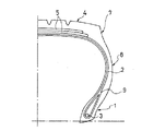
図1〜図3は、本発明の実施形態からなる空気入りタイヤを例示するものである。図において、左右一対のビード部1,1間には、カーカス層2が装架されており、このカーカス層2のタイヤ幅方向両端部がビードコア3に係止されている。トレッド部4におけるカーカス層2の外側には、2層のベルト層5がタイヤ1周にわたって環状に配置されている。
【0012】
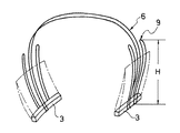
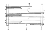
カーカス層2は、図2及び図3に示すように、1本又は複数本のカーカスコード6を左右一対のビードコア3、3間に往復させると共に、左右のビードコア3と各ビードコア3に隣接するショルダー部7との間のサイド領域8にそれぞれ往復させ、これらビードコア3、3間の往復とサイド領域8の往復とをタイヤ周方向に連続的に組み合わせながら延在させることにより形成されている。該サイド領域における往復は、該サイド領域の往復折り返し部のビードコアの内径面からの高さを50mm以上でかつベルト層のエッジの高さまでの範囲内にして延在させて、カーカス層を形成することが肝要である。
【0013】
図においては、カーカスコード6がビードコア3,3間を1往復する間にそれぞれ左右のサイド領域8を1往復するようになっている。しかしながら、この組み合わせのパターン及び比率は、特に限定されることはなく、タイヤ周方向に任意に配置することができる。本発明では、サイド領域8を通過するカーカスコード6の本数をZとし、そのうちビードコア3,3間を往復するカーカスコード6の本数をBとすると、0<B/Z<1の範囲、さらに好ましくは0.2<B/Z<0.6の範囲でカーカス層2を形成するようにすればよい。
【0014】
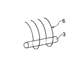
一方、カーカスコード6に対するビードロック構造は、特に限定されることはなく、図4(a)〜(e)のように種々の形態にすることができる。すなわち、図4(a)では、カーカスコード6がビードコア3の外側でサイド領域8を往復するようになっている。図4(b)では、カーカスコード6がビードコア3の周りに螺旋状に巻きつくようにようにビードコア3を挿入している。図4(c)では、カーカスコード6によって形成される一対のループのうち一方のループにビードコア3を挿入している。図4(d)では、カーカスコード6を2本のビードコア3で挟み込むようにしている。更に、図4(e)では、カーカスコード6によって形成される一対のループでビードコア3を内外から挟み込むようにしている。いずれのビードロック構造においても、カーカスコード6が互いに接触することはない。
【0015】
上述のようにカーカスコード6のビードコア3,3間の往復とサイド領域8の往復とをタイヤ周方向に連続的に組み合わせてカーカス層2を形成することにより、カーカス層2が切断破面を有していないので、カーカス層2におけるエッジセパレーションの発生を防止して荷重耐久性を向上することができる。また、サイド領域8における往復折り返し部9ではカーカスコード6がタイヤ周方向に延長するように配置されるので、タイヤ周方向の剛性を高めて操縦安定性や高速耐久性を向上することができる。
【0016】
更に、上述のようにカーカスコード6を左右一対のビードコア3,3間及び左右のサイド領域8に連続的に往復させてカーカス層2を形成するので、従来のようにカレンダー工程や切断工程等の複雑かつ多数の工程を経てカーカス層を形成する必要はなく、タイヤの生産性を高めることができる。従って、本発明では、カーカス層に切断破面を有する空気入りタイヤに比べて、耐久性、操縦安定性及び生産性が優れている。
【0017】
また、上記カーカス構造では、左右のサイド領域8における往復折り返し部9の高さを任意に設定することができるので、サイド部の剛性を自在に調整することが可能となる。これにより、カーカスコード6にタイヤ内圧による張力があまりかからないベルト層5の下方域ではカーカスコード6の使用量を低減してコストダウンを図ることが可能になる。
【0018】
従って、カーカスコードを左右一対のビード部間に切れ目なく連続的に往復させて編み上げた空気入りタイヤに比べて、設計の自由度が大きくなり、かつコストダウンを図ることができる。なお、上記カーカス構造では、全カーカスコード中の少なくとも一部のカーカスコード6が左右一対のビードコア3,3間にわたって往復しているので、タイヤ成形時にインフレート成形を行うことが可能である。
【0019】
本発明において、サイド領域8における往復折り返し部9のビードコア3の内径面からの高さHは、全ての往復折り返し部9をタイヤ周方向に同一にしてもよく、或いはランダムに異ならせるようにしてもよい。このように往復折り返し部9の高さHを種々異ならせることにより、サイド部の剛性を調整することが容易になり、設計の自由度が増大する。また、往復折り返し部9のビードコア3の内径面からの高さHは50mm以上にすることが肝要である。このように往復折り返し部9の高さHを50mm以上にすることにより、サイド部の剛性を十分に確保することができる。また、往復折り返し部9の高さHの上限は、ベルト層5のエッジに対応するところまでとする。
【0020】
【実施例】
タイヤサイズを185/60R14とし、カーカス構造だけを下記のように異ならせた本発明タイヤ1、従来タイヤ及び比較タイヤ1、2を製作した。
【0021】
本発明タイヤ1
カーカスコードを左右一対のビードコア間に往復させると共に、該ビードコアとショルダー部との間の左右のサイド領域に往復させ、これらビードコア間の往復と左右のサイド領域の往復とを図4(a)のようにタイヤ周方向に1対1の割合で交互に組み合わせてカーカス層を形成し、そのサイド領域における往復折り返し部のビードコアからの高さを50mmにした。
【0022】
比較タイヤ1
サイド領域における往復折り返し部のビードコアからの高さを20mmにしたこと以外は本発明タイヤ1と同じカーカス構造にした。
【0023】
従来タイヤ
図5のようにカーカスコードの切断破面を有するカーカス材を左右一対のビード部間に装架し、該カーカス材のタイヤ幅方向両端部をビードコアの周りにタイヤ内側から外側へ巻き上げることにより、カーカスコードの巻き上げ高さを50mmにした。
【0024】
比較タイヤ2
図6のようにカーカスコードを左右一対のビード部間に連続的に往復させてカーカス層を形成した。
【0025】
これら試験タイヤについて、下記の試験方法により、生産性、サイド剛性、操縦安定性、荷重耐久性、カーカスコード使用量を評価し、その結果を表1に示した。
【0026】
生産性:
各試験タイヤについて、単位時間当たりに生産されるタイヤの本数を求め、従来タイヤを100とする指数で示した。この指数値が大きいほど生産性が高いことを示す。
【0027】
サイド剛性:
各試験タイヤについて、タイヤ回転軸方向の剛性を測定し、従来タイヤを100とする指数で示した。この指数値が大きいほどサイド部の周剛性が大きい。
【0028】
操縦安定性:
各試験タイヤを空気圧1.9kg/cm2 で排気量1.6リットルの国産乗用車に装着し、テストドライバーによるフィーリングテストを行った。その評価結果は、従来タイヤを100とする指数で示した。この指数値が大きいほど操縦安定性が優れている。
【0029】
荷重耐久性:
JIS D4230に準拠した試験方法により荷重耐久性を評価し、従来タイヤを100とする指数にて示した。この指数値が大きいほど荷重耐久性が優れている。
【0030】
カーカスコード使用量:
各タイヤについて、カーカスコードの使用量を求め、従来タイヤを100とする指数で示した。この指数値が小さいほどカーカスコードの使用量が少ない。
【0031】
【表1】

この表1から明らかなように、本発明タイヤ1は、切断破面を有するカーカス材を使用した従来タイヤに比べて荷重耐久性、操縦安定性及び生産性が優れていると共に、従来タイヤと略同等のサイド剛性を維持しながらカーカスコードの使用量を低減することができた。
【0033】
【発明の効果】
以上説明したように本発明によれば、カーカスコードを左右一対のビードコア間に往復させると共に、該左右のビードコアと各ビードコアに隣接するショルダー部との間のサイド領域にそれぞれ往復させ、これらビードコア間の往復とサイド領域の往復とをタイヤ周方向に連続的に組み合わせながら延在させてカーカス層を形成することで、カーカス層に切断破面を有する従来の空気入りタイヤに比べて耐久性、操縦安定性、生産性を向上しながら、サイド部の剛性を調整自在にし、しかもカーカスコードの使用量を低減してコストダウンを図ることができる。
【図面の簡単な説明】
【図1】本発明の実施形態からなる空気入りタイヤを例示する子午線断面図である。
【図2】図1のタイヤのカーカス層を示す斜視図である。
【図3】図1のタイヤのカーカス層を示す平面図である。
【図4】(a)〜(e)は、図1のタイヤにおけるビードロック構造を例示する斜視図である。
【図5】従来タイヤのビードロック構造を示す斜視図である。
【図6】比較タイヤのビードロック構造を示す斜視図である。
【符号の説明】
1 ビード部
2 カーカス層
3 ビードコア
6 カーカスコード
7 ショルダー部
8 サイド領域[0001]
BACKGROUND OF THE INVENTION
The present invention relates to a pneumatic tire in which a carcass cord is formed by reciprocating a carcass cord between a pair of left and right bead portions. More specifically, the rigidity of a side portion is improved while improving durability, steering stability, and productivity. The present invention relates to a pneumatic tire that can be adjusted and can reduce cost by reducing the amount of carcass cord used.
[0002]
[Prior art]
Conventionally, when forming a carcass layer to be applied to a general pneumatic radial tire, a belt-like sheet material is obtained by applying a plurality of pre-aligned carcass cords to a calendar process and rubberizing unvulcanized rubber. The rubberized sheet material is cut into a length that is slightly longer than the length of the carcass layer in the longitudinal direction by the winding height at both ends, and one or more of these cut pieces are tired according to the tire size. The carcass material is formed by splicing so as to have a necessary circumferential length in the circumferential direction.
[0003]
The carcass material prepared in this way is transferred to the green tire molding process, wound around a molding drum, then fitted with bead cores at both ends of the outer periphery, and then wrapped around the bead cores at both ends of the carcass material. A green tire is formed by winding and winding side rubber or the like.
[0004]
However, in the carcass layer formed in this manner, a cut fracture surface of the carcass cord is formed at the rolled-up end portion of the carcass material after molding, and this cut fracture surface exists in the tire sidewall portion having a large deformation amount. In many cases, a tire failure is caused by stress concentration on the cut fracture surface. Moreover, in this carcass structure, in order to ensure sufficient rigidity in the circumferential direction of the tire side portion, there is also a problem that a reinforcing layer accompanying an increase in weight must be added as necessary. Furthermore, in order to form such a carcass layer, there are a number of processes such as cutting the sheet material through the calendar process as described above and joining the cut pieces together, which is a factor that reduces productivity. It was.
[0005]
On the other hand, various tires have been proposed in which a carcass structure having no cut fracture surface is formed by continuously knitting a carcass layer from one carcass cord. For example, Japanese Patent Application Laid-Open No. 1-110941 discloses that the carcass structure is formed by sequentially passing a carcass cord between a pair of holding mechanisms arranged in a circle by a reciprocating motion of a rotary arm.
[0006]
However, in the above carcass structure, the carcass cord is knitted by continuously reciprocating between the pair of left and right bead portions, so the rigidity of the side portions cannot be adjusted as necessary, and the degree of freedom in design However, it is practically impossible to reduce the cost by reducing the amount of carcass cord used.
[0007]
[Problems to be solved by the invention]
An object of the present invention is to provide a pneumatic radial tire capable of adjusting the rigidity at the side portion while improving durability, steering stability, and productivity, and reducing the amount of use of the carcass cord to reduce the cost. It is to provide.
[0008]
[Means for Solving the Problems]
In order to achieve the above object, a pneumatic tire according to the present invention is a pneumatic radial tire having a carcass layer and a belt layer formed by radially arranging carcass cords, and reciprocating the carcass cord between a pair of left and right bead cores. Each of the left and right bead cores and a shoulder region adjacent to each bead core are reciprocated respectively, and the reciprocation between these bead cores and the reciprocation of the side regions are continuously combined in the tire circumferential direction , and the side regions The carcass layer is formed by extending the reciprocating folded portion from the inner diameter surface of the bead core to 50 mm or more and up to the height of the edge of the belt layer .
[0009]
In this way, the carcass cord is reciprocated between a pair of left and right bead cores, and is also reciprocated to the left and right side regions between the bead core and the shoulder portion, and the reciprocation between these bead cores and the reciprocation of the side regions are continued in the tire circumferential direction. Since the carcass layer does not have a cut fracture surface by extending while being combined in combination, the occurrence of edge separation in the carcass layer can be prevented and the load durability can be improved. In addition, since the carcass cord is arranged so as to extend in the tire circumferential direction at the reciprocating folded portion in the side region, the rigidity in the tire circumferential direction can be increased and the steering stability and the high-speed durability can be improved.
[0010]
In addition, since the carcass layer is formed by continuously reciprocating the carcass cord between the pair of left and right bead cores and the left and right side regions as described above, a complicated and many processes such as a calendar process and a cutting process are performed as in the past. Thus, it is not necessary to form a carcass layer, and the productivity of the tire can be increased.
Furthermore, in the above carcass structure, the carcass cord can be reciprocated in the left and right side regions, and the height of the reciprocating folded portion can be arbitrarily set, so that the rigidity of the side portion can be freely adjusted, In the lower region of the belt layer where the tension is not applied to the carcass cord, the amount of the carcass cord used can be reduced to reduce the cost.
[0011]
DETAILED DESCRIPTION OF THE INVENTION
Hereinafter, the configuration of the present invention will be described in detail with reference to the accompanying drawings.
1 to 3 illustrate a pneumatic tire according to an embodiment of the present invention. In the figure, a
[0012]
As shown in FIGS. 2 and 3, the
[0013]
In the figure, while the
[0014]
On the other hand, the bead lock structure with respect to the
[0015]
As described above, the
[0016]
Further, as described above, the
[0017]
Moreover, in the said carcass structure, since the height of the reciprocating folding | turning part 9 in the left and right side area | region 8 can be set arbitrarily, it becomes possible to adjust the rigidity of a side part freely. As a result, it is possible to reduce the amount of use of the
[0018]
Therefore, as compared with a pneumatic tire knitted by continuously reciprocating the carcass cord between the pair of left and right bead portions, the degree of freedom in design can be increased and the cost can be reduced. In the carcass structure, since at least a part of the
[0019]
In the present invention, the height H from the inner diameter surface of the
[0020]
【Example】
The tire 1 of the present invention, the conventional tire, and the
[0021]
Invention tire 1
The carcass cord is reciprocated between a pair of left and right bead cores, and is also reciprocated to the left and right side regions between the bead core and the shoulder portion. The reciprocation between these bead cores and the reciprocation of the left and right side regions is shown in FIG. Thus, the carcass layer was formed by alternately combining at a ratio of 1: 1 in the tire circumferential direction, and the height from the bead core of the reciprocating folded portion in the side region was set to 50 mm.
[0022]
Comparative tire 1
The same carcass structure as the tire 1 of the present invention was used except that the height of the reciprocating folded portion in the side region from the bead core was 20 mm.
[0023]
Conventional tire As shown in FIG. 5, a carcass material having a cut fracture surface of a carcass cord is mounted between a pair of left and right bead portions, and both ends in the tire width direction of the carcass material are arranged around the bead core from the inside of the tire. By winding it outward, the winding height of the carcass cord was 50 mm.
[0024]
As shown in FIG. 6, the carcass cord was continuously reciprocated between a pair of left and right bead portions to form a carcass layer.
[0025]
For these test tires, productivity, side rigidity, steering stability, load durability, and carcass cord usage were evaluated by the following test methods, and the results are shown in Table 1.
[0026]
productivity:
For each test tire, the number of tires produced per unit time was determined and indicated as an index with the conventional tire as 100. The larger the index value, the higher the productivity.
[0027]
Side rigidity:
For each test tire, the rigidity in the tire rotation axis direction was measured and indicated by an index with the conventional tire as 100. The larger the index value, the greater the circumferential rigidity of the side portion.
[0028]
Steering stability:
Each test tire was mounted on a domestic passenger car with an air pressure of 1.9 kg / cm 2 and a displacement of 1.6 liters, and a feeling test was conducted by a test driver. The evaluation results are shown as an index with the conventional tire as 100. The larger the index value, the better the steering stability.
[0029]
Load durability:
The load durability was evaluated by a test method based on JIS D4230 and indicated by an index with the conventional tire as 100. The larger the index value, the better the load durability.
[0030]
Carcass cord usage:
About each tire, the usage-amount of the carcass cord was calculated | required and it showed with the index | index which makes the conventional tire 100. The smaller the index value, the smaller the amount of carcass cord used.
[0031]
[Table 1]
As apparent from Table 1, the tire 1 of the present invention is superior in load durability, steering stability and productivity to the conventional tire using the carcass material having the cut fracture surface, and is substantially the same as the conventional tire. It was possible to reduce the amount of carcass cords used while maintaining equivalent side rigidity.
[0033]
【The invention's effect】
As described above, according to the present invention, the carcass cord is reciprocated between the pair of left and right bead cores, and is also reciprocated to the side region between the left and right bead cores and the shoulder portion adjacent to each bead core. The carcass layer is formed by extending the reciprocation of the side region and the reciprocation of the side region continuously in the tire circumferential direction to form a carcass layer, which is more durable and steerable than a conventional pneumatic tire having a cut fracture surface in the carcass layer. While improving the stability and productivity, the rigidity of the side portion can be adjusted, and the amount of the carcass cord used can be reduced to reduce the cost.
[Brief description of the drawings]
FIG. 1 is a meridian cross-sectional view illustrating a pneumatic tire according to an embodiment of the invention.
2 is a perspective view showing a carcass layer of the tire of FIG. 1. FIG.
3 is a plan view showing a carcass layer of the tire of FIG. 1. FIG.
FIGS. 4A to 4E are perspective views illustrating a bead lock structure in the tire of FIG. 1;
FIG. 5 is a perspective view showing a bead lock structure of a conventional tire.
FIG. 6 is a perspective view showing a bead lock structure of a comparative tire.
[Explanation of symbols]
1 Bead
Claims (3)
Priority Applications (1)
| Application Number | Priority Date | Filing Date | Title |
|---|---|---|---|
| JP09746197A JP3774541B2 (en) | 1997-04-15 | 1997-04-15 | Pneumatic radial tire |
Applications Claiming Priority (1)
| Application Number | Priority Date | Filing Date | Title |
|---|---|---|---|
| JP09746197A JP3774541B2 (en) | 1997-04-15 | 1997-04-15 | Pneumatic radial tire |
Publications (2)
| Publication Number | Publication Date |
|---|---|
| JPH10287103A JPH10287103A (en) | 1998-10-27 |
| JP3774541B2 true JP3774541B2 (en) | 2006-05-17 |
Family
ID=14192951
Family Applications (1)
| Application Number | Title | Priority Date | Filing Date |
|---|---|---|---|
| JP09746197A Expired - Fee Related JP3774541B2 (en) | 1997-04-15 | 1997-04-15 | Pneumatic radial tire |
Country Status (1)
| Country | Link |
|---|---|
| JP (1) | JP3774541B2 (en) |
-
1997
- 1997-04-15 JP JP09746197A patent/JP3774541B2/en not_active Expired - Fee Related
Also Published As
| Publication number | Publication date |
|---|---|
| JPH10287103A (en) | 1998-10-27 |
Similar Documents
| Publication | Publication Date | Title |
|---|---|---|
| JP2757940B2 (en) | Pneumatic tire | |
| JPH04290733A (en) | Molding method for band layer | |
| JP2954665B2 (en) | Pneumatic radial tire suitable for high-speed driving | |
| JPH1044721A (en) | Pneumatic radial tire | |
| JP4166308B2 (en) | Pneumatic tire | |
| JP4523704B2 (en) | Pneumatic tire | |
| JP6018740B2 (en) | Pneumatic tire and manufacturing method thereof | |
| JP3715058B2 (en) | Pneumatic tire | |
| JPH05238208A (en) | Pneumatic tire | |
| JP3837219B2 (en) | Pneumatic radial tire | |
| WO2000034059A1 (en) | Tyre for vehicle wheels with improved bead structure | |
| US5355926A (en) | Pneumatic radial tires for two-wheeled vehicles | |
| JP3777241B2 (en) | Pneumatic radial tire | |
| JP3774541B2 (en) | Pneumatic radial tire | |
| JPH0516614A (en) | Pneumatic radial tire | |
| JP3735447B2 (en) | Pneumatic tire | |
| US11772425B2 (en) | Pneumatic tire | |
| JP4800504B2 (en) | Pneumatic tire | |
| JP2000052709A (en) | Pneumatic radial tire | |
| JP3764801B2 (en) | Pneumatic radial tire | |
| JPH07276913A (en) | Pneumatic radial tires | |
| JP2799131B2 (en) | Pneumatic tire | |
| JPH1128915A (en) | Pneumatic tire and its forming method | |
| JP2002154306A (en) | Radial tires for motorcycles | |
| JP3735445B2 (en) | Pneumatic radial tire |
Legal Events
| Date | Code | Title | Description |
|---|---|---|---|
| A621 | Written request for application examination |
Free format text: JAPANESE INTERMEDIATE CODE: A621 Effective date: 20040407 |
|
| A977 | Report on retrieval |
Free format text: JAPANESE INTERMEDIATE CODE: A971007 Effective date: 20050921 |
|
| A131 | Notification of reasons for refusal |
Free format text: JAPANESE INTERMEDIATE CODE: A131 Effective date: 20051025 |
|
| A521 | Request for written amendment filed |
Free format text: JAPANESE INTERMEDIATE CODE: A523 Effective date: 20051215 |
|
| TRDD | Decision of grant or rejection written | ||
| A01 | Written decision to grant a patent or to grant a registration (utility model) |
Free format text: JAPANESE INTERMEDIATE CODE: A01 Effective date: 20060207 |
|
| A61 | First payment of annual fees (during grant procedure) |
Free format text: JAPANESE INTERMEDIATE CODE: A61 Effective date: 20060220 |
|
| R150 | Certificate of patent or registration of utility model |
Free format text: JAPANESE INTERMEDIATE CODE: R150 |
|
| LAPS | Cancellation because of no payment of annual fees |