JP4333542B2 - Icp発光分析装置 - Google Patents
Icp発光分析装置 Download PDFInfo
- Publication number
- JP4333542B2 JP4333542B2 JP2004288846A JP2004288846A JP4333542B2 JP 4333542 B2 JP4333542 B2 JP 4333542B2 JP 2004288846 A JP2004288846 A JP 2004288846A JP 2004288846 A JP2004288846 A JP 2004288846A JP 4333542 B2 JP4333542 B2 JP 4333542B2
- Authority
- JP
- Japan
- Prior art keywords
- plasma
- plasma flame
- plasma torch
- optical system
- cone
- Prior art date
- Legal status (The legal status is an assumption and is not a legal conclusion. Google has not performed a legal analysis and makes no representation as to the accuracy of the status listed.)
- Expired - Fee Related
Links
Images


Landscapes
- Investigating, Analyzing Materials By Fluorescence Or Luminescence (AREA)
Description
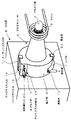
図1は、本発明に係るプラズマトーチを分光器に取り付けたときの外観図であり、図2はプラズマトーチの中心軸を含む縦断面を示す図であり、さらに図3はプラズマトーチの円筒形基台部をプラズマトーチの軸芯に垂直な面で切断した断面を示す図である。これらの図において、プラズマトーチAは、外観上は、円筒形の基台部Dと、それに連続する円錐部分で構成されている。円筒形の基台部Dには、プラズマトーチAにガスを供給する3箇所のガス供給口(クーラントガス入口11、プラズマガス入口12、パージガス入口13)が設けられており、図では省略されているが、それぞれフレキシブルな管でICP発光分析装置のガス流量制御装置に接続される。また、後述するように、プラズマトーチAにはスプレーチェンバー8が内設されており、この中に被測定試料を霧化して供給するためのネブライザー7が着脱自在に挿着されている。ネブライザー7のキャリアガス供給口24と試料導入口23もまた、フレキシブルな管によってそれぞれガス流量制御部と試料容器に接続される。また、図1のLはレベラーで、基台部Dに一体的に付設されている。このレベラーLからの排出液は、適当な管によって廃液槽へ導出される。プラズマトーチAは、固定具20によって分光器Bに定着されている。ただし、固定具20の形状および個数は本実施例に限定されるものではない。また、プラズマトーチAの円錐部の頂点近傍にはコイル2が配設されている。ICP発光分析装置の電源からコイル2に高周波誘導電流が供給され、プラズマトーチAに所定の流量のアルゴンガスが供給されると、プラズマトーチAの円錐端の前方に高温のプラズマ炎1が発生する。
B…分光器
C…ICP質量分析装置
1…プラズマ炎
2…コイル
3…クーラントガス管
4…プラズマガス管
5…キャリアガス管
6…パージガス管
7…ネブライザー
8…スプレーチェンバー
9…試料
D…基台部
10…通気孔
11…クーラントガス入口
12…プラズマガス入口
13…パージガス入口
14…レベラー
L…レベラー
15…開孔
17…集光レンズ
18…焦点
19…分光器入口スリット
20…固定具
21…Oリング
22…サンプリングコーン
23…試料導入口
24…キャリアガス供給口
Claims (3)
- 高周波磁界によってプラズマ炎を発生させ、スプレーチェンバー内でネブライザーによって霧化された試料エアロゾルを、プラズマトーチを介して前記プラズマ炎中に導入し、プラズマ炎の熱によって試料エアロゾル中の試料原子を励起発光させて分析を行うICPプラズマ発光分析装置において、前記プラズマトーチは同軸多層の円錐面により構成される多重管からなり、前記多重管の各々には、試料を霧化するネブライザ、プラズマガス、クーラントガスが供給され、円錐の最内側の空間にはパージガスが供給され、円錐の頂点側に形成されるプラズマ炎を前記円錐の内側の空間を介して円錐の底部側より観測する光学系を設けるとともに、キャリアガスを供給する管の円錐の底部側にはレベラーを設けたことを特徴とするICP発光分析装置。
- 前記光学系は集光光学系で構成され、かつ、この集光光学系の焦点が前記プラズマ炎の最大発光点に設定されていることを特徴とする請求項1記載のICP発光分析装置。
- プラズマトーチの円錐面に平行な円錐形面上に高周波誘導電流コイルが配設されていることを特徴とする請求項1記載のICP発光分析装置。
Priority Applications (1)
| Application Number | Priority Date | Filing Date | Title |
|---|---|---|---|
| JP2004288846A JP4333542B2 (ja) | 2004-09-30 | 2004-09-30 | Icp発光分析装置 |
Applications Claiming Priority (1)
| Application Number | Priority Date | Filing Date | Title |
|---|---|---|---|
| JP2004288846A JP4333542B2 (ja) | 2004-09-30 | 2004-09-30 | Icp発光分析装置 |
Publications (2)
| Publication Number | Publication Date |
|---|---|
| JP2006105616A JP2006105616A (ja) | 2006-04-20 |
| JP4333542B2 true JP4333542B2 (ja) | 2009-09-16 |
Family
ID=36375553
Family Applications (1)
| Application Number | Title | Priority Date | Filing Date |
|---|---|---|---|
| JP2004288846A Expired - Fee Related JP4333542B2 (ja) | 2004-09-30 | 2004-09-30 | Icp発光分析装置 |
Country Status (1)
| Country | Link |
|---|---|
| JP (1) | JP4333542B2 (ja) |
Cited By (2)
| Publication number | Priority date | Publication date | Assignee | Title |
|---|---|---|---|---|
| US10815552B2 (en) | 2013-06-19 | 2020-10-27 | Rio Tinto Alcan International Limited | Aluminum alloy composition with improved elevated temperature mechanical properties |
| US11579092B2 (en) * | 2020-04-23 | 2023-02-14 | Sumco Corporation | Sample introduction device, inductively coupled plasma analyzing device and analyzing method |
Families Citing this family (1)
| Publication number | Priority date | Publication date | Assignee | Title |
|---|---|---|---|---|
| CN116437551A (zh) * | 2023-03-15 | 2023-07-14 | 安徽华东光电技术研究所有限公司 | 微波等离子体炬结构 |
-
2004
- 2004-09-30 JP JP2004288846A patent/JP4333542B2/ja not_active Expired - Fee Related
Cited By (2)
| Publication number | Priority date | Publication date | Assignee | Title |
|---|---|---|---|---|
| US10815552B2 (en) | 2013-06-19 | 2020-10-27 | Rio Tinto Alcan International Limited | Aluminum alloy composition with improved elevated temperature mechanical properties |
| US11579092B2 (en) * | 2020-04-23 | 2023-02-14 | Sumco Corporation | Sample introduction device, inductively coupled plasma analyzing device and analyzing method |
Also Published As
| Publication number | Publication date |
|---|---|
| JP2006105616A (ja) | 2006-04-20 |
Similar Documents
| Publication | Publication Date | Title |
|---|---|---|
| US9804183B2 (en) | Apparatus and method for liquid sample introduction | |
| US9541479B2 (en) | Apparatus and method for liquid sample introduction | |
| JP5841601B2 (ja) | 発光分光分析のための改良型放電箱 | |
| CN105074419B (zh) | 用于组成分析系统的雷射剥蚀单元和火炬系统 | |
| US20110133074A1 (en) | Analytical method and analytical system | |
| US20040183008A1 (en) | Plasma torch | |
| US5012065A (en) | Inductively coupled plasma torch with laminar flow cooling | |
| US20180332697A1 (en) | Torches and systems and methods using them | |
| KR20210083268A (ko) | 광학 입자 센서, 특히 배기 가스 센서 | |
| JP5965743B2 (ja) | Icp装置及び分光分析装置並びに質量分析装置 | |
| US6709632B2 (en) | ICP analyzer | |
| JP4333542B2 (ja) | Icp発光分析装置 | |
| JP4779807B2 (ja) | Icp発光分光分析装置 | |
| McLean et al. | Fundamental properties of aerosols produced in helium by a direct injection nebulizer | |
| JP2010197080A (ja) | 誘導結合プラズマ分析装置 | |
| CN104076024A (zh) | Icp发光分光分析装置 | |
| JP2724541B2 (ja) | Icp発光分光分析装置 | |
| JP2009121846A (ja) | 試料送液ポンプおよび送液ポンプを用いたicp発光分析装置 | |
| SG182967A1 (en) | Collimator arrangements including multiple, collimators and implementation methods thereof | |
| JP2001305059A (ja) | 誘導結合プラズマ発光分光分析装置と方法 | |
| JP2003240718A (ja) | Icp発光分光分析装置 | |
| JP2000074839A (ja) | 保護ガス放出口を設けたicp分光分析装置 | |
| JPH09166545A (ja) | 原子吸光分析装置 | |
| JP2018179555A (ja) | 発光分析装置 | |
| JP2003149155A (ja) | Icp発光分光分析装置 |
Legal Events
| Date | Code | Title | Description |
|---|---|---|---|
| A621 | Written request for application examination |
Free format text: JAPANESE INTERMEDIATE CODE: A621 Effective date: 20070125 |
|
| A977 | Report on retrieval |
Free format text: JAPANESE INTERMEDIATE CODE: A971007 Effective date: 20080919 |
|
| A131 | Notification of reasons for refusal |
Free format text: JAPANESE INTERMEDIATE CODE: A131 Effective date: 20080930 |
|
| A521 | Written amendment |
Free format text: JAPANESE INTERMEDIATE CODE: A523 Effective date: 20081127 |
|
| A131 | Notification of reasons for refusal |
Free format text: JAPANESE INTERMEDIATE CODE: A131 Effective date: 20090310 |
|
| A521 | Written amendment |
Free format text: JAPANESE INTERMEDIATE CODE: A523 Effective date: 20090508 |
|
| TRDD | Decision of grant or rejection written | ||
| A01 | Written decision to grant a patent or to grant a registration (utility model) |
Free format text: JAPANESE INTERMEDIATE CODE: A01 Effective date: 20090602 |
|
| A01 | Written decision to grant a patent or to grant a registration (utility model) |
Free format text: JAPANESE INTERMEDIATE CODE: A01 |
|
| A61 | First payment of annual fees (during grant procedure) |
Free format text: JAPANESE INTERMEDIATE CODE: A61 Effective date: 20090615 |
|
| FPAY | Renewal fee payment (event date is renewal date of database) |
Free format text: PAYMENT UNTIL: 20120703 Year of fee payment: 3 |
|
| FPAY | Renewal fee payment (event date is renewal date of database) |
Free format text: PAYMENT UNTIL: 20120703 Year of fee payment: 3 |
|
| FPAY | Renewal fee payment (event date is renewal date of database) |
Free format text: PAYMENT UNTIL: 20120703 Year of fee payment: 3 |
|
| FPAY | Renewal fee payment (event date is renewal date of database) |
Free format text: PAYMENT UNTIL: 20130703 Year of fee payment: 4 |
|
| LAPS | Cancellation because of no payment of annual fees |