JP4573676B2 - 櫛歯電極対形成方法 - Google Patents
櫛歯電極対形成方法 Download PDFInfo
- Publication number
- JP4573676B2 JP4573676B2 JP2005069155A JP2005069155A JP4573676B2 JP 4573676 B2 JP4573676 B2 JP 4573676B2 JP 2005069155 A JP2005069155 A JP 2005069155A JP 2005069155 A JP2005069155 A JP 2005069155A JP 4573676 B2 JP4573676 B2 JP 4573676B2
- Authority
- JP
- Japan
- Prior art keywords
- comb
- mask
- electrode
- conductor
- conductor layer
- Prior art date
- Legal status (The legal status is an assumption and is not a legal conclusion. Google has not performed a legal analysis and makes no representation as to the accuracy of the status listed.)
- Expired - Fee Related
Links
Images


Classifications
-
- G—PHYSICS
- G02—OPTICS
- G02B—OPTICAL ELEMENTS, SYSTEMS OR APPARATUS
- G02B6/00—Light guides; Structural details of arrangements comprising light guides and other optical elements, e.g. couplings
- G02B6/24—Coupling light guides
- G02B6/26—Optical coupling means
- G02B6/35—Optical coupling means having switching means
- G02B6/351—Optical coupling means having switching means involving stationary waveguides with moving interposed optical elements
- G02B6/3512—Optical coupling means having switching means involving stationary waveguides with moving interposed optical elements the optical element being reflective, e.g. mirror
- G02B6/3518—Optical coupling means having switching means involving stationary waveguides with moving interposed optical elements the optical element being reflective, e.g. mirror the reflective optical element being an intrinsic part of a MEMS device, i.e. fabricated together with the MEMS device
-
- B—PERFORMING OPERATIONS; TRANSPORTING
- B81—MICROSTRUCTURAL TECHNOLOGY
- B81C—PROCESSES OR APPARATUS SPECIALLY ADAPTED FOR THE MANUFACTURE OR TREATMENT OF MICROSTRUCTURAL DEVICES OR SYSTEMS
- B81C1/00—Manufacture or treatment of devices or systems in or on a substrate
- B81C1/00436—Shaping materials, i.e. techniques for structuring the substrate or the layers on the substrate
- B81C1/00523—Etching material
- B81C1/00547—Etching processes not provided for in groups B81C1/00531 - B81C1/00539
-
- G—PHYSICS
- G02—OPTICS
- G02B—OPTICAL ELEMENTS, SYSTEMS OR APPARATUS
- G02B26/00—Optical devices or arrangements for the control of light using movable or deformable optical elements
- G02B26/08—Optical devices or arrangements for the control of light using movable or deformable optical elements for controlling the direction of light
- G02B26/0816—Optical devices or arrangements for the control of light using movable or deformable optical elements for controlling the direction of light by means of one or more reflecting elements
- G02B26/0833—Optical devices or arrangements for the control of light using movable or deformable optical elements for controlling the direction of light by means of one or more reflecting elements the reflecting element being a micromechanical device, e.g. a MEMS mirror, DMD
-
- B—PERFORMING OPERATIONS; TRANSPORTING
- B81—MICROSTRUCTURAL TECHNOLOGY
- B81B—MICROSTRUCTURAL DEVICES OR SYSTEMS, e.g. MICROMECHANICAL DEVICES
- B81B2201/00—Specific applications of microelectromechanical systems
- B81B2201/03—Microengines and actuators
- B81B2201/033—Comb drives
-
- Y—GENERAL TAGGING OF NEW TECHNOLOGICAL DEVELOPMENTS; GENERAL TAGGING OF CROSS-SECTIONAL TECHNOLOGIES SPANNING OVER SEVERAL SECTIONS OF THE IPC; TECHNICAL SUBJECTS COVERED BY FORMER USPC CROSS-REFERENCE ART COLLECTIONS [XRACs] AND DIGESTS
- Y10—TECHNICAL SUBJECTS COVERED BY FORMER USPC
- Y10S—TECHNICAL SUBJECTS COVERED BY FORMER USPC CROSS-REFERENCE ART COLLECTIONS [XRACs] AND DIGESTS
- Y10S359/00—Optical: systems and elements
- Y10S359/904—Micromirror
Landscapes
- Engineering & Computer Science (AREA)
- Physics & Mathematics (AREA)
- Manufacturing & Machinery (AREA)
- Microelectronics & Electronic Packaging (AREA)
- General Physics & Mathematics (AREA)
- Optics & Photonics (AREA)
- Micromachines (AREA)
- Mechanical Light Control Or Optical Switches (AREA)
- Photovoltaic Devices (AREA)
- Printers Or Recording Devices Using Electromagnetic And Radiation Means (AREA)
Description
10,30 揺動部
11,31,61 ミラー支持部
12,32 アーム部
13,14,23,24,33,34,43,44 櫛歯電極
13A,14A,23A,24A,33A,34A,43A,44A 電極歯
21,41,62 フレーム
22,42,63 トーションバー
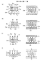
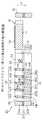
70,80 材料基板
70a,70b,80a,80b シリコン層
70c,80c 絶縁層
71’,81’ プリ酸化膜パターン
71,81,82 酸化膜パターン
72,83 レジストパターン
73,84 レジスト膜
Claims (2)
- 第1導体層と、第2導体層と、当該第1および第2導体層の間の絶縁層とからなる積層構造を有する材料基板に対して加工を施すことにより、相対的に変位して、それぞれが有する電極歯が部分的に対面しうる姿勢をとりうる一対の櫛歯電極を形成するための方法であって、
前記一対の櫛歯電極は、前記第1導体層に由来する第1導体部と、前記第2導体層に由来する第2導体部と、前記絶縁層に由来する絶縁部とからなる積層構造を有する第1櫛歯電極、および、前記第2導体層に由来する第2櫛歯電極からなり、
前記第1導体層上にプリ第1マスクパターンを形成する工程と、
前記プリ第1マスクパターン上の第1櫛歯電極用の第1マスク部、および、前記第1導体層上の第2櫛歯電極用の第2マスク部、を含む第2マスクパターンを、前記プリ第1マスクパターン上および前記第1導体層上にわたって形成する工程と、
前記第2マスクパターンを介して前記プリ第1マスクパターンに対してエッチング処理を施し、前記第2マスクパターンの前記第1マスク部に対応するパターン形状を有する第1櫛歯電極用の第3マスク部、を含む第1マスクパターンを、前記プリ第1マスクパターンから形成する、第1エッチング工程と、
前記第1および第2マスクパターンを介して前記第1導体層に対して前記絶縁層に至るまでエッチング処理を施し、重なり合う前記第1および第3マスク部にマスクされた第1導体部、および、前記第2マスク部にマスクされた第1残存マスク部を、前記第1導体層において前記材料基板の厚さ方向に対して傾斜をもって形成する、第2エッチング工程と、
前記絶縁層に対して第1導体層側から前記第2導体層に至るまでエッチング処理を施し、前記第1導体部にマスクされた絶縁部、および、前記第1残存マスク部にマスクされた第2残存マスク部を、前記絶縁層において形成する、第3エッチング工程と、
前記第2マスクパターンを除去する工程と、
前記第2導体層に対して第1導体層側からエッチング処理を施し、前記第1残存マスク部を除去しつつ、前記絶縁部に接する第2導体部、および、前記第2残存マスク部にマスクされた第2櫛歯電極を、前記第2導体層において形成する、第4エッチング工程と、を含み、
前記第2エッチング工程における前記傾斜は、前記第1櫛歯電極の電極歯と前記第2櫛歯電極の電極歯とが部分的に対面するとき、それらが互いに平行な配向となるような傾斜である、櫛歯電極対形成方法。 - 第1導体層と、第2導体層と、当該第1および第2導体層の間の絶縁層とからなる積層構造を有する材料基板に対して加工を施すことにより、相対的に変位して、それぞれが有する電極歯が部分的に対面しうる姿勢をとりうる一対の櫛歯電極を形成するための方法であって、
前記一対の櫛歯電極は、前記第1導体層に由来する第1櫛歯電極、および、前記第2導体層に由来する第2櫛歯電極からなり、
前記第1導体層上にプリ第1マスクパターンを形成する工程と、
前記プリ第1マスクパターン上の第1櫛歯電極用の第1マスク部、および、前記第1導体層上の第2櫛歯電極用の第2マスク部、を含む第2マスクパターンを、前記プリ第1マスクパターン上および前記第1導体層上にわたって形成する工程と、
前記第2マスクパターンを介して前記プリ第1マスクパターンに対してエッチング処理を施し、前記第2マスクパターンの前記第1マスク部に対応するパターン形状を有する第1櫛歯電極用の第3マスク部、を含む第1マスクパターンを、前記プリ第1マスクパターンから形成する、第1エッチング工程と、
第2櫛歯電極用の第4マスク部を含む第3マスクパターンを前記第2導体層上に形成す
る工程と、
前記第1および第2マスクパターンを介して前記第1導体層に対して前記絶縁層に至るまでエッチング処理を施し、重なり合う前記第1および第3マスク部にマスクされた第1櫛歯電極、および、前記第2マスク部にマスクされた第1残存マスク部を、前記第1導体層において前記材料基板の厚さ方向に対して傾斜をもって形成する、第2エッチング工程と、
前記絶縁層に対して第1導体層側から前記第2導体層に至るまでエッチング処理を施し、前記第1残存マスク部にマスクされた第2残存マスク部を、前記絶縁層において形成する、第3エッチング工程と、
前記第2マスクパターンを除去する工程と、
前記第2導体層に対して第1導体層側から当該第2導体層の厚さ方向の途中までエッチング処理を施し、前記第1残存マスク部を除去しつつ、前記第2残存マスク部にマスクされた第2櫛歯電極の一部を、前記第2導体層において形成する、第4エッチング工程と、
前記第3マスクパターンを介して前記第2導体層に対してエッチング処理を施し、前記第2櫛歯電極の残部を形成する、第5エッチング工程と、を含み、
前記第2エッチング工程における前記傾斜は、前記第1櫛歯電極の電極歯と前記第2櫛歯電極の電極歯とが部分的に対面するとき、それらが互いに平行な配向となるような傾斜である、櫛歯電極対形成方法。
Priority Applications (5)
| Application Number | Priority Date | Filing Date | Title |
|---|---|---|---|
| JP2005069155A JP4573676B2 (ja) | 2005-03-11 | 2005-03-11 | 櫛歯電極対形成方法 |
| TW095104910A TWI309069B (en) | 2005-03-11 | 2006-02-14 | Method of making comb-teeth electrode pair |
| KR1020060018003A KR100786739B1 (ko) | 2005-03-11 | 2006-02-24 | 빗살 전극쌍 형성 방법 |
| CNB2006100597450A CN100410724C (zh) | 2005-03-11 | 2006-03-06 | 梳齿电极对的制造方法 |
| US11/371,089 US7439184B2 (en) | 2005-03-11 | 2006-03-09 | Method of making comb-teeth electrode pair |
Applications Claiming Priority (1)
| Application Number | Priority Date | Filing Date | Title |
|---|---|---|---|
| JP2005069155A JP4573676B2 (ja) | 2005-03-11 | 2005-03-11 | 櫛歯電極対形成方法 |
Publications (2)
| Publication Number | Publication Date |
|---|---|
| JP2006247793A JP2006247793A (ja) | 2006-09-21 |
| JP4573676B2 true JP4573676B2 (ja) | 2010-11-04 |
Family
ID=36970541
Family Applications (1)
| Application Number | Title | Priority Date | Filing Date |
|---|---|---|---|
| JP2005069155A Expired - Fee Related JP4573676B2 (ja) | 2005-03-11 | 2005-03-11 | 櫛歯電極対形成方法 |
Country Status (5)
| Country | Link |
|---|---|
| US (1) | US7439184B2 (ja) |
| JP (1) | JP4573676B2 (ja) |
| KR (1) | KR100786739B1 (ja) |
| CN (1) | CN100410724C (ja) |
| TW (1) | TWI309069B (ja) |
Families Citing this family (20)
| Publication number | Priority date | Publication date | Assignee | Title |
|---|---|---|---|---|
| JP4138736B2 (ja) * | 2004-12-02 | 2008-08-27 | 富士通株式会社 | マイクロ揺動素子 |
| JP4321507B2 (ja) * | 2005-09-27 | 2009-08-26 | パナソニック電工株式会社 | バーティカルコムアクチュエータの製造方法 |
| JP4534931B2 (ja) * | 2005-09-27 | 2010-09-01 | パナソニック電工株式会社 | バーティカルコムアクチュエータの製造方法 |
| KR100790878B1 (ko) | 2006-06-13 | 2008-01-03 | 삼성전자주식회사 | 상하 구조가 디커플된 콤전극의 자기정렬 식각 방법 |
| KR100790879B1 (ko) | 2006-06-13 | 2008-01-03 | 삼성전자주식회사 | 맴스 디바이스의 콤전극 형성 방법 |
| WO2008072248A2 (en) * | 2006-12-14 | 2008-06-19 | Ramot At Tel-Aviv University Ltd. | Tilting actuator with close-gap electrodes |
| JP4477659B2 (ja) * | 2007-06-29 | 2010-06-09 | 富士通株式会社 | マイクロ揺動素子およびマイクロ揺動素子アレイ |
| JP2009014768A (ja) | 2007-06-29 | 2009-01-22 | Fujitsu Ltd | メムスデバイスおよびその製造方法 |
| JP2009113128A (ja) * | 2007-11-02 | 2009-05-28 | Fujitsu Ltd | マイクロ揺動素子およびマイクロ揺動素子製造方法 |
| DE102008005521B4 (de) | 2008-01-23 | 2019-01-03 | Robert Bosch Gmbh | Kapazitiver Wandler und Verfahren zur Herstellung desselben |
| JP5056633B2 (ja) * | 2008-07-14 | 2012-10-24 | 富士通株式会社 | マイクロ揺動素子、マイクロ揺動素子アレイ、および光スイッチング装置 |
| JP2011095621A (ja) * | 2009-10-30 | 2011-05-12 | Furukawa Electric Co Ltd:The | 光スイッチ素子の製造方法、光スイッチ素子、光スイッチ装置、およびmems素子の製造方法 |
| CN103086316B (zh) * | 2011-10-28 | 2015-07-22 | 中国科学院上海微系统与信息技术研究所 | Mems垂直梳齿微镜面驱动器的制作方法 |
| JP6927530B2 (ja) * | 2018-11-16 | 2021-09-01 | 国立大学法人 東京大学 | 櫛歯型素子の製造方法 |
| WO2020171029A1 (ja) * | 2019-02-19 | 2020-08-27 | 株式会社村田製作所 | 測定器 |
| CN113994175B (zh) * | 2019-06-07 | 2025-03-14 | 株式会社村田制作所 | 测定器 |
| US11387748B2 (en) * | 2019-08-30 | 2022-07-12 | Taiwan Semiconductor Manufacturing Company, Ltd. | Self-aligned dielectric liner structure for protection in MEMS comb actuator |
| DE102020106474B4 (de) | 2019-08-30 | 2023-09-28 | Taiwan Semiconductor Manufacturing Co. Ltd. | Selbstgefluchtete dielektrische verkleidungsstruktur zum schutz in einem mems-kammaktuator |
| CN111446359B (zh) * | 2020-05-15 | 2023-05-30 | 京东方科技集团股份有限公司 | 一种压电器件及其制作方法、电子装置及控制方法 |
| CN116209348A (zh) * | 2021-11-29 | 2023-06-02 | 北京超弦存储器研究院 | 梳形电容器及其制造方法 |
Family Cites Families (16)
| Publication number | Priority date | Publication date | Assignee | Title |
|---|---|---|---|---|
| JP3178123B2 (ja) * | 1992-02-25 | 2001-06-18 | 富士電機株式会社 | 櫛歯式アクチュエータの製造方法 |
| JPH10190007A (ja) | 1996-12-25 | 1998-07-21 | Mitsubishi Materials Corp | 半導体慣性センサの製造方法 |
| JPH10270714A (ja) | 1997-03-26 | 1998-10-09 | Mitsubishi Materials Corp | 半導体慣性センサの製造方法 |
| JPH11214706A (ja) * | 1998-01-27 | 1999-08-06 | Toyota Motor Corp | 半導体センサおよびその製造方法 |
| US6287885B1 (en) | 1998-05-08 | 2001-09-11 | Denso Corporation | Method for manufacturing semiconductor dynamic quantity sensor |
| JP4265016B2 (ja) | 1998-05-08 | 2009-05-20 | 株式会社デンソー | 半導体力学量センサの製造方法 |
| US6229640B1 (en) * | 1999-08-11 | 2001-05-08 | Adc Telecommunications, Inc. | Microelectromechanical optical switch and method of manufacture thereof |
| US6612029B2 (en) * | 2000-03-24 | 2003-09-02 | Onix Microsystems | Multi-layer, self-aligned vertical combdrive electrostatic actuators and fabrication methods |
| JP2003015064A (ja) * | 2001-07-04 | 2003-01-15 | Fujitsu Ltd | マイクロミラー素子 |
| JP3827977B2 (ja) * | 2001-08-20 | 2006-09-27 | 富士通株式会社 | マイクロミラー素子の製造方法 |
| US6713367B2 (en) | 2001-08-28 | 2004-03-30 | The Board Of Trustees Of The Leland Stanford Junior University | Self-aligned vertical combdrive actuator and method of fabrication |
| JP2003241120A (ja) | 2002-02-22 | 2003-08-27 | Japan Aviation Electronics Industry Ltd | 光デバイス |
| JP3987382B2 (ja) * | 2002-06-11 | 2007-10-10 | 富士通株式会社 | マイクロミラー素子およびその製造方法 |
| JP4285005B2 (ja) * | 2003-01-16 | 2009-06-24 | ソニー株式会社 | 三次元構造体およびその製造方法、並びに電子機器 |
| JP2005088188A (ja) * | 2003-08-12 | 2005-04-07 | Fujitsu Ltd | マイクロ揺動素子およびマイクロ揺動素子駆動方法 |
| JP4252889B2 (ja) | 2003-08-12 | 2009-04-08 | 富士通株式会社 | マイクロ構造体の製造方法 |
-
2005
- 2005-03-11 JP JP2005069155A patent/JP4573676B2/ja not_active Expired - Fee Related
-
2006
- 2006-02-14 TW TW095104910A patent/TWI309069B/zh not_active IP Right Cessation
- 2006-02-24 KR KR1020060018003A patent/KR100786739B1/ko not_active Expired - Fee Related
- 2006-03-06 CN CNB2006100597450A patent/CN100410724C/zh not_active Expired - Fee Related
- 2006-03-09 US US11/371,089 patent/US7439184B2/en active Active
Also Published As
| Publication number | Publication date |
|---|---|
| CN1831579A (zh) | 2006-09-13 |
| KR100786739B1 (ko) | 2007-12-18 |
| US7439184B2 (en) | 2008-10-21 |
| JP2006247793A (ja) | 2006-09-21 |
| US20060203319A1 (en) | 2006-09-14 |
| TWI309069B (en) | 2009-04-21 |
| KR20060097593A (ko) | 2006-09-14 |
| CN100410724C (zh) | 2008-08-13 |
| TW200638505A (en) | 2006-11-01 |
Similar Documents
| Publication | Publication Date | Title |
|---|---|---|
| JP4573676B2 (ja) | 櫛歯電極対形成方法 | |
| US7476950B2 (en) | Micro-oscillating element and method of making the same | |
| JP5470767B2 (ja) | マイクロ可動素子製造方法 | |
| US7903313B2 (en) | Micro movable element | |
| US7453182B2 (en) | Micro oscillating element | |
| JP4477659B2 (ja) | マイクロ揺動素子およびマイクロ揺動素子アレイ | |
| JP4138736B2 (ja) | マイクロ揺動素子 | |
| JP4464186B2 (ja) | マイクロ揺動素子 | |
| JP5240203B2 (ja) | マイクロ可動素子およびマイクロ可動素子アレイ | |
| JP4919750B2 (ja) | マイクロ構造体製造方法およびマイクロ構造体 | |
| JP4150003B2 (ja) | マイクロ構造体の製造方法およびマイクロ構造体 | |
| JP4285005B2 (ja) | 三次元構造体およびその製造方法、並びに電子機器 | |
| JP2009113128A (ja) | マイクロ揺動素子およびマイクロ揺動素子製造方法 | |
| JP4598795B2 (ja) | マイクロ揺動素子およびマイクロ揺動素子アレイ | |
| JP5309905B2 (ja) | マイクロ可動素子、マイクロ可動素子アレイ、および光スイッチング装置 | |
| JP4129045B2 (ja) | マイクロ揺動素子および可動機能素子 | |
| JP4537439B2 (ja) | マイクロ揺動素子 | |
| JP2005046958A (ja) | マイクロ構造体 | |
| JP2009037247A (ja) | マイクロミラー素子およびマイクロミラーアレイ |
Legal Events
| Date | Code | Title | Description |
|---|---|---|---|
| A131 | Notification of reasons for refusal |
Free format text: JAPANESE INTERMEDIATE CODE: A131 Effective date: 20090317 |
|
| A977 | Report on retrieval |
Free format text: JAPANESE INTERMEDIATE CODE: A971007 Effective date: 20090319 |
|
| A521 | Request for written amendment filed |
Free format text: JAPANESE INTERMEDIATE CODE: A523 Effective date: 20090514 |
|
| A131 | Notification of reasons for refusal |
Free format text: JAPANESE INTERMEDIATE CODE: A131 Effective date: 20100126 |
|
| A521 | Request for written amendment filed |
Free format text: JAPANESE INTERMEDIATE CODE: A523 Effective date: 20100329 |
|
| TRDD | Decision of grant or rejection written | ||
| A01 | Written decision to grant a patent or to grant a registration (utility model) |
Free format text: JAPANESE INTERMEDIATE CODE: A01 Effective date: 20100810 |
|
| A01 | Written decision to grant a patent or to grant a registration (utility model) |
Free format text: JAPANESE INTERMEDIATE CODE: A01 |
|
| A61 | First payment of annual fees (during grant procedure) |
Free format text: JAPANESE INTERMEDIATE CODE: A61 Effective date: 20100817 |
|
| R150 | Certificate of patent or registration of utility model |
Ref document number: 4573676 Country of ref document: JP Free format text: JAPANESE INTERMEDIATE CODE: R150 Free format text: JAPANESE INTERMEDIATE CODE: R150 |
|
| FPAY | Renewal fee payment (event date is renewal date of database) |
Free format text: PAYMENT UNTIL: 20130827 Year of fee payment: 3 |
|
| LAPS | Cancellation because of no payment of annual fees |