JP5116676B2 - Spot welding tong including compensation unit with curved connector element - Google Patents
Spot welding tong including compensation unit with curved connector element Download PDFInfo
- Publication number
- JP5116676B2 JP5116676B2 JP2008527259A JP2008527259A JP5116676B2 JP 5116676 B2 JP5116676 B2 JP 5116676B2 JP 2008527259 A JP2008527259 A JP 2008527259A JP 2008527259 A JP2008527259 A JP 2008527259A JP 5116676 B2 JP5116676 B2 JP 5116676B2
- Authority
- JP
- Japan
- Prior art keywords
- spot welding
- tongue
- connector element
- tong
- drive device
- Prior art date
- Legal status (The legal status is an assumption and is not a legal conclusion. Google has not performed a legal analysis and makes no representation as to the accuracy of the status listed.)
- Expired - Fee Related
Links
- 238000003466 welding Methods 0.000 title claims abstract description 90
- 230000002093 peripheral effect Effects 0.000 claims 1
- 238000000034 method Methods 0.000 description 5
- 238000007373 indentation Methods 0.000 description 4
- 239000000725 suspension Substances 0.000 description 4
- 238000012423 maintenance Methods 0.000 description 2
- 238000006243 chemical reaction Methods 0.000 description 1
- 238000010586 diagram Methods 0.000 description 1
- 238000011156 evaluation Methods 0.000 description 1
Images


Classifications
-
- B—PERFORMING OPERATIONS; TRANSPORTING
- B23—MACHINE TOOLS; METAL-WORKING NOT OTHERWISE PROVIDED FOR
- B23K—SOLDERING OR UNSOLDERING; WELDING; CLADDING OR PLATING BY SOLDERING OR WELDING; CUTTING BY APPLYING HEAT LOCALLY, e.g. FLAME CUTTING; WORKING BY LASER BEAM
- B23K11/00—Resistance welding; Severing by resistance heating
- B23K11/30—Features relating to electrodes
- B23K11/31—Electrode holders and actuating devices therefor
- B23K11/314—Spot welding guns, e.g. mounted on robots
-
- B—PERFORMING OPERATIONS; TRANSPORTING
- B23—MACHINE TOOLS; METAL-WORKING NOT OTHERWISE PROVIDED FOR
- B23K—SOLDERING OR UNSOLDERING; WELDING; CLADDING OR PLATING BY SOLDERING OR WELDING; CUTTING BY APPLYING HEAT LOCALLY, e.g. FLAME CUTTING; WORKING BY LASER BEAM
- B23K11/00—Resistance welding; Severing by resistance heating
- B23K11/30—Features relating to electrodes
- B23K11/31—Electrode holders and actuating devices therefor
- B23K11/317—Equalizing; Balancing devices for electrode holders
Landscapes
- Engineering & Computer Science (AREA)
- Mechanical Engineering (AREA)
- Robotics (AREA)
- Resistance Welding (AREA)
- Load-Engaging Elements For Cranes (AREA)
- Sheet Holders (AREA)
- Joining Of Building Structures In Genera (AREA)
- Pit Excavations, Shoring, Fill Or Stabilisation Of Slopes (AREA)
Abstract
Description
本発明は、トングベース体と、二つのトングアームと、トングアームのうちの一方をトングベース体に移動可能に結び付けるとともに回転運動を直線運動に変換するように構成された一つの補正ユニットと、を含む、トング補正を備えたスポット熔接トングに関する。そして、補正ユニットは、駆動装置及びコネクタ要素からなり、コネクタ要素は駆動装置に固定された偏心ディスクに対して偏心して且つ移動可能に固定される。 The present invention includes a tong base body, two tong arms, one correction unit configured to movably connect one of the tong arms to the tong base body and convert rotational motion into linear motion, To spot welding tongs with tong correction. The correction unit includes a drive device and a connector element, and the connector element is fixed to be eccentric and movable relative to an eccentric disk fixed to the drive device.
このタイプのスポット熔接トングは、例えば、国際出願第02/078892号(WO 02/078892 A1)から知られている。当該特許出願において、駆動装置の回転運動をコネクタ要素の長手方向の動きに変換することにより、偏心タペットを介してコネクタ要素に結合された駆動装置を通じて補正動作が達成される。 This type of spot welding tong is known, for example, from WO 02/077882 (WO 02/078892 A1). In this patent application, a corrective action is achieved through a drive coupled to the connector element via an eccentric tappet by converting the rotational movement of the drive into a longitudinal movement of the connector element.
ドイツ国特許出願公開明細書第103 44 056号(DE 103 44 056 A1)から、補正ユニットを備えたスポット熔接トングを得ることができる。当該特許出願において、補正駆動は、偏心駆動装置を介して、溶接トングの関節レバーと結合されている。スポット熔接トングは、さらに、別個の補正駆動装置が簡単で且つ機械的な手段と置換される後者(偏心駆動装置)によって除去されるように構成されている。 From German patent application DE 103 44 056 (DE 103 44 056 A1) it is possible to obtain spot welding tongs with a correction unit. In this patent application, the corrective drive is coupled to the articulation lever of the welding tongue via an eccentric drive. The spot welding tongs are further configured so that a separate correction drive is removed by the latter (eccentric drive) which is replaced by simple and mechanical means.
ネジ山(thread)によって回転運動を直線運動に変換する補正ユニットは、先行技術により知られている。例えば、ドイツ国実用新案出願公開明細書第202 14 970号(DE 202 14 970 U1)から、補正デバイスを含むロボット溶接トングが知られている。当該実用新案出願において、スピンドルは電動機によって駆動される。また、そこから得られた直線運動は、平衡を保つ動きとして溶接トングのトングアームに用いられる。その場合でのスピンドルが自動ロックであるので、補正ユニットは補正動作(compensation movement)のサスペンションを可能にするようにばねのような弾性要素を備えるように構成されている。 Correction units that convert rotational motion into linear motion by means of threads are known from the prior art. For example, from German Utility Model Application Publication No. 202 14 970 (DE 202 14 970 U1), a robot welding tong including a correction device is known. In the utility model application, the spindle is driven by an electric motor. Further, the linear motion obtained therefrom is used for the tong arm of the welding tong as a motion for keeping balance. Since the spindle in that case is self-locking, the compensation unit is configured with a spring-like elastic element so as to allow a suspension of compensation movement.
しかしながら、補正ユニットのかかる構成が、補正動作のサスペンション用の追加の弾性要素を必要とすることは不利である。これは高い構造上費用及び維持費用を含んでいる。さらに、かかるスピンドル駆動装置は、多くの熱の問題を伴う。多くの熱の問題は、スピンドル駆動装置によってもたらされた高い摩擦ロスに起因している。 However, it is disadvantageous that such a configuration of the correction unit requires an additional elastic element for the suspension of the correction operation. This includes high structural and maintenance costs. Furthermore, such spindle drives are associated with a number of thermal problems. Many thermal problems are due to the high friction loss caused by the spindle drive.
本発明の目的は、トング補正(compensation)を備えたスポット熔接トングを提供することである。前記補正ユニットは、簡単なやり方で電動機の回転運動をトングアームの直線運動(つまり補正動作)に変換する。先行技術の欠点は、回避されるか少なくとも低減される。 The object of the present invention is to provide a spot welded tong with tong compensation. The correction unit converts the rotational movement of the electric motor into the linear movement of the tongue arm (ie, the correction operation) in a simple manner. The disadvantages of the prior art are avoided or at least reduced.
本発明の目的は、コネクタ要素が端部領域で湾曲されているように構成されていることにより達成される。補正ユニットのコネクタ要素のかかる構成は、駆動装置の回転運動を直線運動に最適に変換することを保証する。それには、回転運動を直線運動に変換することがクランク構造によって達成されるという長所がある。したがって、構造が簡単で且つ非複雑に実現され、維持することが簡単なことは同様に好適である。 The object of the invention is achieved by the connector element being configured to be curved in the end region. Such a configuration of the connector element of the correction unit ensures that the rotational movement of the drive device is optimally converted into a linear movement. It has the advantage that the crank structure can achieve the conversion of rotational movement into linear movement. Accordingly, it is equally suitable that the structure is simple and non-complicated and easy to maintain.
好ましくは、請求項2乃至6に規定された本発明に係る補正ユニットの構成は、弾性的作用を備えた追加の要素が必要でないように、補正ユニットの自動ロックの動作を妨げる。
Preferably, the configuration of the correction unit according to the invention as defined in
駆動装置が好ましくはトングのベース体上に配置されるか又はトングアームのうちの一方の上に配置される測定(measure)は、それぞれ、駆動装置又は補正ユニットの柔軟性のある配置のオプションを提供する。 A measure in which the drive is preferably located on the base of the tongue or on one of the tong arms is a flexible placement option for the drive or correction unit, respectively. provide.
好ましくは、コネクタ要素上に設けられる測定する(measuring)要素は、正確で力に関連する制御が正確に画定された補正力に対して達成されることを保証する。 Preferably, a measuring element provided on the connector element ensures that accurate and force related control is achieved for a precisely defined correction force.
本発明は、添付した模式図により詳細に説明される。 The present invention will be described in detail with reference to the accompanying schematic drawings.
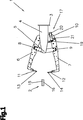
図1は、ワークピース2の抵抗溶接用のスポット熔接トング1を示している。スポット熔接トング1は、ロボットによって好ましくは操作される。その固定は、トングベース体4の端へ取り付けられるロボットフランジ3によって実現される。トングベース体4の他方の端は、ピン5が、全体のスポット熔接トング1に対する回転軸を形成し、その回転軸を中心にして、トングアーム6及びさらにトングアーム7がピボットアーム8,9によってピン5に回転可能に取り付けられているように構成されている。ピン5とロボットフランジ3との間において、トングアーム6,7は主駆動装置10によってお互いに結合されている。このようにして、いわゆるX字のスポット熔接トング1が形成される。トングアーム6,7の正面の領域において、特に、それらの前方端部において、電極ホルダ11,12は、電極13,14をそれぞれ保持するように配置されている。
FIG. 1 shows a spot welding tong 1 for resistance welding of a
溶接プロセスの間に、溶接されるワークピース2は電極13,14の間に位置して、前記ワークピースは、例えば、二つのコンポーネント15,16で構成されている。溶接手順を行なうために、スポット熔接トング1は、最初にロボットによって位置決めされなければならない。この目的のために、スポット熔接トング1は、図1に係る開状態にある、つまり、開始位置又はオリジナル位置にある。図2乃至4において、スポット熔接トング1の個々の操作ステップは、抵抗溶接操作の実現まで示される。
During the welding process, the
ロボットが前に固定されたコンポーネント15,16で溶接位置にスポット熔接トング1を位置決めすることができる前に、トングアーム6,7は十分に開かれなければならない。これは主駆動装置10によって達成される。主駆動装置10は、全く反対のやり方でトングアーム6,7を動かす。コンポーネント15,16の形状、コンポーネント15,16の公差、及びロボットの位置決め精度を考慮に入れて、トングアーム6,7が開く。
The
開いている間に、トングアーム6,7が非接触でワークピース2の溶接位置へもたらされるようにロボットが出発点又は基準点(reference point)を要求することは同様に考慮に入れられるだろう。基準点は、例えば、コンポーネント16と電極14との接触面上に画定される。電極14の接触面が実際に基準点を含むために、電極14が取り付けられたトングアーム7は、補正ユニット17によってトングベース体4に結合されている。スポット熔接トング1のコントローラーによって達成される補正ユニット17を適切に作動させることによって、トングアーム7、又は電極14の接触面は、基準点上に維持される。スポット熔接トング1がいずれかの可能な溶接位置にある同じ場所で維持されることはそれによって保証される。
It would be similarly taken into account that the robot requires a starting point or reference point so that the
このように、補正ユニット17は、特にロボットの位置決め手順の間に、スポット熔接トング1、又はトングアーム6,7を絶えず同じ位置に保持させる。このように、ロボットは、容易に、且つ、特に、非接触で、コンポーネント15,16の所望の溶接位置に、スポット熔接トング1及びトングアーム6,7を位置決めすることができる。
In this way, the
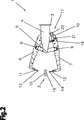
位置決め手順の間に、基準点又は電極14の接触面は、図2から明らかなように、コンポーネント15,16の溶接位置の下方に画定された距離、例えば2cmで位置決めされる。溶接場所では、電極13,14は、お互いに溶接されるコンポーネント15,16に実質的に法線方向に(normally)延在するように位置決めされる。位置決めが終わった後に、ロボットは、トング・コントローラーへメッセージを送り、その結果として抵抗溶接を可能にする。コンポーネント15,16の溶接場所で抵抗溶接操作を行なうために、トングアーム6,7はお互いの方へ移動される。そうする際に、補正ユニット17の制御に対する様々なオプションがある。
During the positioning procedure, the reference point or contact surface of the
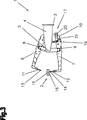
図3によれば、力センサーによって決定される所定の力によって、又は補正ユニット17のモータ電流の評価によって電極14がコンポーネント16と接触するまで、抵抗溶接は、例えば、補正ユニット17がトングアーム7及び電極14をコンポーネント16に動かすという点で行なわれる。補正ユニット17を適切に制御することによりトングアーム7は溶接手順の終わりまでこの位置に維持される。この後に、図4から明らかなように、必要で所定の圧力が電極13,14の間にあるコンポーネント15,16に印加されるまで、主駆動装置10はトングアーム6及び電極13をコンポーネント15に移動させる。その結果として、溶接装置から供給された所定の電流は、コンポーネント15,16の抵抗溶接を行なうために電極13,14を通じて導かれる。
According to FIG. 3, resistance welding is performed, for example, by the
電極14とコンポーネント16との間の距離、例えば2cmに実質的に対応する所定距離まで、トングアーム6が主駆動装置10によってコンポーネント15に移動されるように、抵抗溶接操作が起こることは同様に可能である。その結果として、補正ユニット17は、非作動であるか、又は例えば、好ましくはスポット熔接トング1の予め決められた閉止角度から、電流無しで(currentless)切り替えられる。それによって、トングアーム6,7は、ワークピース2の中央に位置決めして、主駆動装置10が抵抗溶接の実行のために必要な所定の圧力を印加する。そして、この種の動きによって、補正ユニット17によって係合したトングアーム6又は7が、コンポーネント15,16上の電極13,14の自動アバットメント(abutment)を保証するように自由に移動可能であることは、補正ユニット17の撤去によって到達される。
Similarly, the resistance welding operation occurs such that the
抵抗溶接を実行するためのさらなる変形例では、補正ユニット17の制御は、後者が例えば所定の電流で電力供給されるようにして達成される。スポット熔接トング1が限界の程度まで移動可能である間それらの位置に維持されるように電流のレベルが選ばれる。これによって、補正動作のサスペンションは、ワークピース2又はコンポーネント15,16のいかなる変形を防止することができる。上記のように、トングアーム6,7は、再び、ワークピース2の中央に位置決めされ、主駆動装置10が、抵抗溶接の実行のために必要な所定の圧力を印加する。
In a further variant for performing resistance welding, the control of the
抵抗溶接操作の完了に際して、スポット熔接トング1又はトングアーム6,7は、図2のように、それらの開始位置に戻される。また、図1のように、スポット熔接トング1をそのオリジナル位置へ戻すことは可能である。更に、スポット熔接トング1は、図1又は図2のように、戻された後に、コンポーネント15,16を次の溶接位置に移動させることができる。
Upon completion of the resistance welding operation, the spot welding tongs 1 or
抵抗溶接の記載された変形例を行なうための本発明に係る補正ユニット17は、補正ユニット17が、駆動装置18と、駆動装置18上に偏心して配置されたコネクタ要素19とから構成されるように構成されている。このように、コネクタ要素19は、駆動装置18の回転運動をトングアーム6又は7の直線運動に変換させる。補正ユニット17の補正動作の必要なサスペンションは、駆動装置18の適切な制御によって達成される。そして、維持費を最小にする補正ユニット17の簡単な構造が提供される。
The
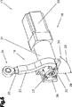
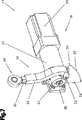
本発明に係る補正ユニット17のセットアップは、図5から明白である。図6及び7は、補正動作をするための異なった位置にある補正ユニット17を示す。
The setup of the
補正ユニット17の駆動装置18は、電動機20及びギヤー21を、好ましくは遊星歯車を実質的に備える。駆動装置18及び特に電動機20は、軸22によって回転運動を行なう。その回転運動はコネクタ要素19によって直線運動に変換される。この目的のために、偏心ディスク23は軸22に対して固定されて取り付けられる。偏心ディスク23は、その中心に設けられたくぼみ24を介して、例えばねじ及びディスクによって形成された固定手段25の助けを借りて回転可能なように軸22に固定される。このように、偏心ディスク23は軸22に相応して回転する。更に、レバー26は偏心ディスク23上に配置される。そのレバーは、コネクタ要素19を固定するための穴27を備える。偏心ディスク23上に穴27を偏心して配置することは、つまり補正動作の穴27に固定されたコネクタ要素19によって、偏心ディスク23の回転運動を、直線運動に変換させる。
The
図6及び7から明らかなように、偏心ディスク23及びレバー26の回転の範囲28(例えば90°)は、実質的に補正動作のために役立つであろう。好ましくは、回転の範囲28がレバー23の270°位置つまりくぼみ24の垂直方向の下方にある下端位置29と、レバー26の360°位置つまりくぼみ24の水平方向に上端位置30との間にある。コネクタ要素19がこの回転運動を直線運動に変換することを可能にするために、例えばスクリュー及びディスクによって形成された固定手段25によって、前者は回転可能なように軸22に対して固定されるように構成されている。したがって、偏心ディスク23は、軸22に対応して回転する。
As is apparent from FIGS. 6 and 7, the range of rotation 28 (eg 90 °) of the
さらに、レバー26は、偏心ディスク23の上に配置される。レバー26は、コネクタ要素19に固定するための穴27を備える。
Further, the
穴27を偏心ディスク23の上に配置することは、例えば補正動作の穴27に固定されたコネクタ要素19を介して、偏心ディスク23の回転を直線運動に変換させる。
Placing the
図6及び7から明らかなように、偏心ディスク23及びレバー26の回転の範囲28(例えば90°)は、実質的に補正動作のために役立つであろう。好ましくは、回転の範囲28がレバー23の270°位置つまりくぼみ24の垂直方向の下方にある下端位置29と、レバー26の360°位置つまりくぼみ24の水平方向に上端位置30と、の間にある。コネクタ要素19がこの回転運動を直線運動に変換することを可能にするために、前者は構成されている。このように、コネクタ要素19は二つの形を備える。
As is apparent from FIGS. 6 and 7, the range of rotation 28 (eg 90 °) of the
レバー26に固定される端部領域は、実質的に偏心ディスク23に一致するように湾曲している。レバー26に固定される端部領域には穴31が設けられている。
An end region fixed to the
前記穴31は、ピン32を介してコネクタ要素19をレバー26の穴27に対して回転可能に固定する役目をする。この目的のために、コネクタ要素19の湾曲した端部領域は、レバー26に相応して形成されたくぼみを含んでいる。
The
このように、コネクタ要素19の湾曲した端部領域はレバー26を取り囲む(enclose)。コネクタ要素19の、湾曲した端部領域の反対側に位置する端部領域は、ウェブ(web)33として構成されている。
In this way, the curved end region of the
ウェブ33は、例えば、トングベース体4に移動可能なアタッチメントとして役立つ。好ましくは、ウェブ33の移動可能なアタッチメントは、例えばネジ山によって、ウェブ33に着脱可能に接続されたアイボルト34又は接続ロッドの助けを借りて実現される。
The
そのネジ山によって、距離の調整も実現可能になる。アイボルト34をウェブ33に固定するために、ウェブ33は雌ねじ(internal thread)を備える。雌ねじにおいて、ナット35は、いわゆる逆(counter)ナットとして固定のためにさらに用いられる。
The screw thread also makes it possible to adjust the distance. In order to fix the
補正ユニット17のかかる構成により、レバー26に対して回転可能に取付られて固定されたコネクタ要素19を介して、駆動装置18と、軸22に固定された偏心ディスク23との回転運動を直線運動に変換することが可能になる。
With this configuration of the
この目的のために、駆動装置18は、例えば、トングアーム7に取り付けられる。また、コネクタ要素19のウェブ33に結び付いているアイボルト34は、トングベース体4に固定される。
For this purpose, the
同様に、駆動装置18はトングアーム6に固定されてもよい。又は、アイボルト34は、トングアーム6,7のうちの一方に固定されてもよく、それに対応して、駆動装置18はトングベース体4に固定されてもよい。これは、補正ユニット17の配置に関係なく必要な補正動作を保証するだろう。
Similarly, the driving
トングアーム7の補正動作は、駆動装置18を上昇させること又は下降させることにより達成される。それはトングアーム7の長手方向の軸に取り付けられる。
The correcting operation of the
このように、アイボルト34は、補正ユニット17のための静止しているが回転可能なピボットを構成する。
Thus, the
補正ユニット17によってトングアーム6,7を上昇させること及び下降させることは、電動機20の力の消費をできるだけ低く達成される。補正ユニット17の調整は必要である。電動機20のための力の最低の消費は、回転の範囲28で実質的に提供される。したがって、補正動作のための電動機20及びレバー26の回転運動(つまり、基準点からコンポーネント16と接触するまで)は、回転の範囲28内で起こることが好ましい。
Raising and lowering the
基準点は、スポット熔接トング1の位置決め用のロボットによって必要とされる。前記基準点は、既に知られているように、例えば、電極14の接触面を構成する。
The reference point is required by the robot for positioning the spot welding tongue 1. As already known, the reference point constitutes a contact surface of the
基準点から、トングアーム7の位置が得られている。駆動装置18は、例えばいくつかの部分から構成される角度ブラケット(angle bracket)36を介してトングアーム7に固定される。
The position of the
このことから、コネクタ要素19用の長さが得られている。コネクタ要素19の長さは、アイボルト34のネジ山、及びウェブ33中に設けられた雌ねじによって、それぞれ調節される。
From this, the length for the
コネクタ要素19の湾曲した端部領域が、レバー26にある上端位置30の領域においてレバー26に固定されるときに、正確な長さが調節されている。
When the curved end region of the
したがって、穴31を穴27に固定するために、偏心ディスク23は、軸22に固定されるか、又は電動機20の適切な制御によって位置決めされる。
Thus, to fix the
基準点については、図6から明らかなように、レバー26の位置が例えば上端位置30に近い。
Regarding the reference point, as is apparent from FIG. 6, the position of the
レバー26の位置が、回転の範囲28の中央領域にあることは、基準点にとって同様に実現可能である。
The position of the
補正動作の完成に際して、つまり、コンポーネント16が電極14の接触面に接触されるように、図7に示されるように、レバー26の位置は回転の範囲28の中央領域に帰着している。
Upon completion of the corrective action, i.e., the
回転の範囲28の下端位置29の近くのレバー26の位置は、また、基準点に対するレバー26の位置の関数として、補正動作の後に得られる。
The position of the
補正ユニット17の調整の後に、つまり、レバー26が回転の範囲28で移動しているときに、抵抗溶接は実現可能である。
Resistance welding is feasible after adjustment of the
前記の調整によって、基準点は定義され、ロボットの制御のために知られるだろう。 With this adjustment, a reference point is defined and will be known for robot control.
ロボットのコントローラーは、言いかえると、スポット熔接トング1及び補正ユニット17のコントローラー(つまりトング・コントローラー)及び溶接装置のコントローラーと連関している。 In other words, the controller of the robot is associated with the controller of the spot welding tongue 1 and the correction unit 17 (that is, the tongue controller) and the controller of the welding apparatus.
そして、ロボットは、抵抗溶接のためのコンポーネント15,16の溶接位置でスポット熔接トング1を位置決めすることができる。
Then, the robot can position the spot welding tongue 1 at the welding position of the
このあとに、駆動装置18及び電動機20は、図7から明らかなように、回転の範囲28内にある下端位置29の方向にレバー26が移動して、補正動作を行なうように最初に制御される。
After this, the
コネクタ要素19のウェブ33がアイボルト34及び駆動装置18を介して静止してトングベース体4に固定されているので、トングアーム7及び電極14は、図3に示されているように、コンポーネント16に移動される。
Since the
図3に係る補正動作も、トングアーム7が所定の力によってコンポーネント16で適用される(apply)という点で達成される。この目的のために、力測定センサー又は歪みゲージは、例えば、ウェブ33の領域に設けられる。
The correction action according to FIG. 3 is also achieved in that the
そして、一旦所定の力が到達したならば、これはトング・コントローラーに信号を伝えるだろう。 And once the predetermined force is reached, this will signal the tongs controller.
コネクタ要素19の湾曲した端部領域が偏心ディスク23上で隣接するように補正動作を行なうことも可能である。
It is also possible to perform the correction operation so that the curved end region of the
これは、コネクタ要素19が補正動作の間に偏心ディスク23に移動するという点で達成される。
This is achieved in that the
偏心ディスク23上のコネクタ要素19のアバットメント(abutment)が、所定のやり方で起こるために、ねじは、例えば、レバー26より上に設けられるか、又はコネクタ要素19上に設けられる。
In order for the abutment of the
ねじの回転は、アバットメント(abutment)の調整を可能にし、したがって、電極14の位置の調整を可能にする。
The rotation of the screw allows adjustment of the abutment and thus allows adjustment of the position of the
そして、抵抗溶接は、主駆動装置10が所定の溶接力によってトングアーム6,7を閉じることによって実行することができる。
And resistance welding can be performed when the
図4で既に示されたように、コンポーネント15,16の抵抗溶接操作の完成の後に、トングアーム7は主駆動装置10によって開かれる。このあとに、レバー26と、電極14の接触面とは、再び位置決めされて、駆動装置18の適切な制御によって基準点上で保持される。
As already shown in FIG. 4, after completion of the resistance welding operation of the
そして、ロボットは、それぞれの抵抗溶接操作を行なうために、次の溶接位置にスポット熔接トング1を位置決めすることができる。 Then, the robot can position the spot welding tongue 1 at the next welding position in order to perform each resistance welding operation.
補正ユニット17のかかる構成及びスポット熔接トング1上でのそのポジショニング又は調整は、回転の範囲28内の補正動作のための短距離に帰着する。
Such a configuration of the
したがって、駆動装置18に対する力の最小の消費(expenditure)が得られている。
Thus, a minimum consumption of force on the
電動機20のための力の消費は、ギヤー21を用いることによりさらに最小化することができる。
The power consumption for the
この場合、電動機18の回転運動がギヤー21によって変換されて、偏心ディスク23がギヤー21によって回転するように、駆動装置18は構成される。
In this case, the driving
しかしながら、補正動作を行なうための電動機20のための力の消費の低下は、電動機20への熱負荷の最小化を保証するだろう。
However, a reduction in power consumption for the
このように、電動機20及び全体的な駆動装置18の寿命が増加するであろう。
In this way, the life of the
スポット熔接トング1に対する、本発明に係る補正ユニット17は、スポット熔接トング1のいずれかの構成で使用される。そして、例えば、C形のスポット熔接トング1又はC-スポット熔接トングである。
The
したがって、補正ユニット17が異なったスポット熔接トング実施態様で用いられることを可能にするために、コネクタ要素19の形を適合させることは実現可能である。
It is therefore feasible to adapt the shape of the
コネクタ要素19は、例えばウェブ形状であり、したがって、偏心ディスク23の形が適合されている。
The
Claims (14)
前記補正ユニット(17)は、駆動装置(18)及びコネクタ要素(19)を備え、
前記コネクタ要素(19)は、前記駆動装置(18)に固定された偏心ディスク(23)に対して偏心して移動可能に固定されていて、
前記偏心ディスク(23)の一部分が、前記コネクタ要素(19)を回転可能に固定するための穴(27)を含むレバー(26)として構成されており、
前記コネクタ要素(19)の湾曲した端部領域の端部領域が、穴(31)を通じて前記レバー(26)に固定されており、前記湾曲した端部領域が、偏心ディスク(23)の外周面に対応して湾曲していて、前記偏心ディスク(23)の下端位置(29)及び上端位置(30)の間での回転の範囲(28)において、前記湾曲した端部領域が前記偏心ディスク(23)に対して近づくか遠ざかるように構成されていることを特徴とするスポット熔接トング(1)。A tongue base body (4), two tong arms (6, 7), and one of the tong arms (6, 7) is movably connected to the tongue base body (4) and rotational movement is linearly moved. A spot welding tong (1) with tong correction comprising a correction unit (17) configured to convert to
The correction unit (17) includes a drive device (18) and a connector element (19),
The connector element (19) is fixed so as to be movable eccentrically with respect to an eccentric disk (23) fixed to the drive device (18),
A portion of the eccentric disk (23) is configured as a lever (26) including a hole (27) for rotatably fixing the connector element (19),
An end region of the curved end region of the connector element (19) is fixed to the lever (26) through a hole (31), and the curved end region is an outer peripheral surface of the eccentric disk (23). In the range of rotation (28) between the lower end position (29) and the upper end position (30) of the eccentric disk (23), the curved end region is the eccentric disk ( 23) Spot welding tongs (1) characterized in that they are configured to approach or move away from 23) .
Applications Claiming Priority (3)
| Application Number | Priority Date | Filing Date | Title |
|---|---|---|---|
| ATA1392/2005 | 2005-08-23 | ||
| AT0139205A AT502424B1 (en) | 2005-08-23 | 2005-08-23 | SPOT WELDING TONG |
| PCT/AT2006/000345 WO2007022553A1 (en) | 2005-08-23 | 2006-08-18 | Spot welding tongs with a balancing unit comprising a curved connector element |
Publications (2)
| Publication Number | Publication Date |
|---|---|
| JP2009505832A JP2009505832A (en) | 2009-02-12 |
| JP5116676B2 true JP5116676B2 (en) | 2013-01-09 |
Family
ID=37188994
Family Applications (1)
| Application Number | Title | Priority Date | Filing Date |
|---|---|---|---|
| JP2008527259A Expired - Fee Related JP5116676B2 (en) | 2005-08-23 | 2006-08-18 | Spot welding tong including compensation unit with curved connector element |
Country Status (8)
| Country | Link |
|---|---|
| US (1) | US8866037B2 (en) |
| EP (1) | EP1919649B1 (en) |
| JP (1) | JP5116676B2 (en) |
| CN (1) | CN101247918B (en) |
| AT (2) | AT502424B1 (en) |
| DE (1) | DE502006005799D1 (en) |
| ES (1) | ES2336482T3 (en) |
| WO (1) | WO2007022553A1 (en) |
Families Citing this family (5)
| Publication number | Priority date | Publication date | Assignee | Title |
|---|---|---|---|---|
| DE112011103453T5 (en) * | 2010-10-14 | 2013-08-14 | Norgren Gmbh | Method and device for balancing the electrode arms of a welding device |
| DE102011002620A1 (en) * | 2011-01-13 | 2012-07-19 | Ford Global Technologies, Llc | welding processes |
| DE102017220816A1 (en) * | 2017-11-22 | 2019-05-23 | Robert Bosch Gmbh | JOINTING DEVICE AND METHOD FOR ADDING AT LEAST ONE COMPONENT USING AN X-ZANGE |
| CN108098127B (en) * | 2018-02-06 | 2024-08-09 | 武汉汉孚装备技术有限公司 | Welding tongs die repair compensation device and method and welding tongs device |
| CN111299792B (en) * | 2019-07-01 | 2021-08-06 | 北京实耐固连接技术有限公司 | Self-adaptive system and self-adaptive adjusting method for resistance welding tongs |
Family Cites Families (15)
| Publication number | Priority date | Publication date | Assignee | Title |
|---|---|---|---|---|
| SE7610437L (en) * | 1975-09-30 | 1977-03-31 | Wunsch Erich | ADJUSTMENT OR ADJUSTMENT DEVICE ON MOTOR VEHICLE MIRRORS |
| FR2674780B1 (en) * | 1991-04-08 | 1995-06-23 | Aro | TOOL CONTROL SYSTEM COMPRISING A CLAMP CONTROLLED BY AN AUTOMATIC POSITIONING SYSTEM. |
| CN2093057U (en) * | 1991-04-13 | 1992-01-15 | 金贵铜 | Functional hanging type point welding pincers |
| CN2180391Y (en) * | 1993-04-05 | 1994-10-26 | 汪伊国 | Portable U type spot-welder |
| US5581138A (en) * | 1993-06-21 | 1996-12-03 | Matsushita Electric Industrial Co., Ltd. | Compact motor with speed reducing mechanism |
| JP2860890B2 (en) * | 1995-08-25 | 1999-02-24 | 株式会社電元社製作所 | Pressurized drive for electric pressurized gun |
| DE69708805T2 (en) * | 1996-09-13 | 2002-04-11 | Dengensha Mfg. Co. Ltd., Kawasaki | Motorized resistance spot welding machine |
| JP4036349B2 (en) * | 1998-04-03 | 2008-01-23 | Obara株式会社 | Electrode pressure drive device for C-type electric welding machine |
| JP2001025880A (en) * | 1999-05-07 | 2001-01-30 | Nissan Motor Co Ltd | Spot welding equipment |
| JP2002096177A (en) * | 2000-09-20 | 2002-04-02 | Nissan Motor Co Ltd | Welding gun position correction method and apparatus |
| FR2822743B1 (en) * | 2001-03-29 | 2003-08-08 | Aro | ASSEMBLY CLIPPERS WITH SELF-ADAPTIVE CALIBRATION AND BALANCING DEVICE |
| JP2002224847A (en) * | 2001-12-18 | 2002-08-13 | Obara Corp | X type electric welding machine |
| DE20214970U1 (en) | 2002-09-27 | 2004-01-08 | Kuka Schweissanlagen Gmbh | Robot welding tongs, used in welding devices, comprises a tongs unit, arranged in a frame, having arms and a drive, and an equalization unit for the tongs unit having two spring elements and a controllable bracing unit |
| US6909064B2 (en) * | 2003-04-07 | 2005-06-21 | Progressive Tool & Industries Co. | Pinch weld gun with swivel shunt connection |
| DE10344056B4 (en) * | 2003-09-23 | 2005-09-22 | Siemens Ag | Welding tongs with fixable balancing device |
-
2005
- 2005-08-23 AT AT0139205A patent/AT502424B1/en not_active IP Right Cessation
-
2006
- 2006-08-18 ES ES06760828T patent/ES2336482T3/en not_active Expired - Lifetime
- 2006-08-18 US US11/990,313 patent/US8866037B2/en not_active Expired - Fee Related
- 2006-08-18 EP EP06760828A patent/EP1919649B1/en not_active Expired - Lifetime
- 2006-08-18 CN CN200680030692.8A patent/CN101247918B/en not_active Expired - Fee Related
- 2006-08-18 JP JP2008527259A patent/JP5116676B2/en not_active Expired - Fee Related
- 2006-08-18 WO PCT/AT2006/000345 patent/WO2007022553A1/en not_active Ceased
- 2006-08-18 AT AT06760828T patent/ATE453481T1/en active
- 2006-08-18 DE DE502006005799T patent/DE502006005799D1/en not_active Expired - Lifetime
Also Published As
| Publication number | Publication date |
|---|---|
| EP1919649B1 (en) | 2009-12-30 |
| CN101247918B (en) | 2010-11-10 |
| US20090050607A1 (en) | 2009-02-26 |
| AT502424B1 (en) | 2007-06-15 |
| AT502424A1 (en) | 2007-03-15 |
| JP2009505832A (en) | 2009-02-12 |
| CN101247918A (en) | 2008-08-20 |
| ES2336482T3 (en) | 2010-04-13 |
| DE502006005799D1 (en) | 2010-02-11 |
| EP1919649A1 (en) | 2008-05-14 |
| WO2007022553A1 (en) | 2007-03-01 |
| ATE453481T1 (en) | 2010-01-15 |
| US8866037B2 (en) | 2014-10-21 |
Similar Documents
| Publication | Publication Date | Title |
|---|---|---|
| CN110646281B (en) | A tensile testing machine suitable for low cycle fatigue testing | |
| JP2007521967A (en) | Clamping tool with compensation system, especially welding pliers | |
| JP2009544473A (en) | press | |
| CN106113009B (en) | A multifunctional plane manipulator system | |
| JP2009505832A (en) | Spot welding tong including compensation unit with curved connector element | |
| CN106911264B (en) | Light and small single-piezoelectric stack-driven bidirectional rotary inertial actuator and actuating method | |
| CN211103599U (en) | Clamping and fixing device for metal surface machining | |
| KR20080087691A (en) | Presser foot device of sewing machine | |
| JP2019064189A (en) | Adjusting apparatus for friction adjusting part of section | |
| JP5505210B2 (en) | Axis adjuster for material testing machine | |
| JP5388083B2 (en) | Electric drive unit for X gun | |
| KR200471851Y1 (en) | Ultrasonic welding apparatus | |
| JP2008191065A (en) | Motion base | |
| CN112173988B (en) | A kind of hoisting equipment and auxiliary device for correction plate of ring polishing machine | |
| JP3597378B2 (en) | Pressurization control method for electric spot welder | |
| WO2000010767A1 (en) | Resistance welding device | |
| CN210426339U (en) | Articulated arm measuring machine | |
| KR20090044079A (en) | Joint actuator module for micro robot | |
| CN207736311U (en) | A kind of work-handling manipulator | |
| CN109396713B (en) | Clamping tool suitable for front frame welding | |
| CN223493240U (en) | A robotic arm for frying food | |
| CN220018791U (en) | Pneumatic actuator torque measuring machine | |
| CN216634418U (en) | Clamping manipulator for machining mechanical parts | |
| CN111660079A (en) | Position-adjustable assembling device | |
| CN223363034U (en) | Load switch capable of performing angle adjustment |
Legal Events
| Date | Code | Title | Description |
|---|---|---|---|
| A131 | Notification of reasons for refusal |
Free format text: JAPANESE INTERMEDIATE CODE: A131 Effective date: 20110222 |
|
| A521 | Request for written amendment filed |
Free format text: JAPANESE INTERMEDIATE CODE: A523 Effective date: 20110520 |
|
| A131 | Notification of reasons for refusal |
Free format text: JAPANESE INTERMEDIATE CODE: A131 Effective date: 20111206 |
|
| A521 | Request for written amendment filed |
Free format text: JAPANESE INTERMEDIATE CODE: A523 Effective date: 20120305 |
|
| TRDD | Decision of grant or rejection written | ||
| A01 | Written decision to grant a patent or to grant a registration (utility model) |
Free format text: JAPANESE INTERMEDIATE CODE: A01 Effective date: 20120918 |
|
| A01 | Written decision to grant a patent or to grant a registration (utility model) |
Free format text: JAPANESE INTERMEDIATE CODE: A01 |
|
| A61 | First payment of annual fees (during grant procedure) |
Free format text: JAPANESE INTERMEDIATE CODE: A61 Effective date: 20121016 |
|
| R150 | Certificate of patent or registration of utility model |
Free format text: JAPANESE INTERMEDIATE CODE: R150 Ref document number: 5116676 Country of ref document: JP Free format text: JAPANESE INTERMEDIATE CODE: R150 |
|
| FPAY | Renewal fee payment (event date is renewal date of database) |
Free format text: PAYMENT UNTIL: 20151026 Year of fee payment: 3 |
|
| R250 | Receipt of annual fees |
Free format text: JAPANESE INTERMEDIATE CODE: R250 |
|
| R250 | Receipt of annual fees |
Free format text: JAPANESE INTERMEDIATE CODE: R250 |
|
| R250 | Receipt of annual fees |
Free format text: JAPANESE INTERMEDIATE CODE: R250 |
|
| R250 | Receipt of annual fees |
Free format text: JAPANESE INTERMEDIATE CODE: R250 |
|
| R250 | Receipt of annual fees |
Free format text: JAPANESE INTERMEDIATE CODE: R250 |
|
| R250 | Receipt of annual fees |
Free format text: JAPANESE INTERMEDIATE CODE: R250 |
|
| LAPS | Cancellation because of no payment of annual fees |