JP5698258B2 - 車両用ブレーキシステム - Google Patents
車両用ブレーキシステム Download PDFInfo
- Publication number
- JP5698258B2 JP5698258B2 JP2012544305A JP2012544305A JP5698258B2 JP 5698258 B2 JP5698258 B2 JP 5698258B2 JP 2012544305 A JP2012544305 A JP 2012544305A JP 2012544305 A JP2012544305 A JP 2012544305A JP 5698258 B2 JP5698258 B2 JP 5698258B2
- Authority
- JP
- Japan
- Prior art keywords
- brake
- vehicle
- electric motor
- cylinder
- hydraulic pressure
- Prior art date
- Legal status (The legal status is an assumption and is not a legal conclusion. Google has not performed a legal analysis and makes no representation as to the accuracy of the status listed.)
- Active
Links
Images



Classifications
-
- B—PERFORMING OPERATIONS; TRANSPORTING
- B60—VEHICLES IN GENERAL
- B60T—VEHICLE BRAKE CONTROL SYSTEMS OR PARTS THEREOF; BRAKE CONTROL SYSTEMS OR PARTS THEREOF, IN GENERAL; ARRANGEMENT OF BRAKING ELEMENTS ON VEHICLES IN GENERAL; PORTABLE DEVICES FOR PREVENTING UNWANTED MOVEMENT OF VEHICLES; VEHICLE MODIFICATIONS TO FACILITATE COOLING OF BRAKES
- B60T13/00—Transmitting braking action from initiating means to ultimate brake actuator with power assistance or drive; Brake systems incorporating such transmitting means, e.g. air-pressure brake systems
- B60T13/74—Transmitting braking action from initiating means to ultimate brake actuator with power assistance or drive; Brake systems incorporating such transmitting means, e.g. air-pressure brake systems with electrical assistance or drive
- B60T13/745—Transmitting braking action from initiating means to ultimate brake actuator with power assistance or drive; Brake systems incorporating such transmitting means, e.g. air-pressure brake systems with electrical assistance or drive acting on a hydraulic system, e.g. a master cylinder
-
- B—PERFORMING OPERATIONS; TRANSPORTING
- B60—VEHICLES IN GENERAL
- B60T—VEHICLE BRAKE CONTROL SYSTEMS OR PARTS THEREOF; BRAKE CONTROL SYSTEMS OR PARTS THEREOF, IN GENERAL; ARRANGEMENT OF BRAKING ELEMENTS ON VEHICLES IN GENERAL; PORTABLE DEVICES FOR PREVENTING UNWANTED MOVEMENT OF VEHICLES; VEHICLE MODIFICATIONS TO FACILITATE COOLING OF BRAKES
- B60T8/00—Arrangements for adjusting wheel-braking force to meet varying vehicular or ground-surface conditions, e.g. limiting or varying distribution of braking force
- B60T8/32—Arrangements for adjusting wheel-braking force to meet varying vehicular or ground-surface conditions, e.g. limiting or varying distribution of braking force responsive to a speed condition, e.g. acceleration or deceleration
- B60T8/34—Arrangements for adjusting wheel-braking force to meet varying vehicular or ground-surface conditions, e.g. limiting or varying distribution of braking force responsive to a speed condition, e.g. acceleration or deceleration having a fluid pressure regulator responsive to a speed condition
- B60T8/36—Arrangements for adjusting wheel-braking force to meet varying vehicular or ground-surface conditions, e.g. limiting or varying distribution of braking force responsive to a speed condition, e.g. acceleration or deceleration having a fluid pressure regulator responsive to a speed condition including a pilot valve responding to an electromagnetic force
- B60T8/3615—Electromagnetic valves specially adapted for anti-lock brake and traction control systems
- B60T8/3675—Electromagnetic valves specially adapted for anti-lock brake and traction control systems integrated in modulator units
- B60T8/368—Electromagnetic valves specially adapted for anti-lock brake and traction control systems integrated in modulator units combined with other mechanical components, e.g. pump units, master cylinders
- B60T8/3685—Electromagnetic valves specially adapted for anti-lock brake and traction control systems integrated in modulator units combined with other mechanical components, e.g. pump units, master cylinders characterised by the mounting of the modulator unit onto the vehicle
-
- B—PERFORMING OPERATIONS; TRANSPORTING
- B60—VEHICLES IN GENERAL
- B60T—VEHICLE BRAKE CONTROL SYSTEMS OR PARTS THEREOF; BRAKE CONTROL SYSTEMS OR PARTS THEREOF, IN GENERAL; ARRANGEMENT OF BRAKING ELEMENTS ON VEHICLES IN GENERAL; PORTABLE DEVICES FOR PREVENTING UNWANTED MOVEMENT OF VEHICLES; VEHICLE MODIFICATIONS TO FACILITATE COOLING OF BRAKES
- B60T8/00—Arrangements for adjusting wheel-braking force to meet varying vehicular or ground-surface conditions, e.g. limiting or varying distribution of braking force
- B60T8/32—Arrangements for adjusting wheel-braking force to meet varying vehicular or ground-surface conditions, e.g. limiting or varying distribution of braking force responsive to a speed condition, e.g. acceleration or deceleration
- B60T8/34—Arrangements for adjusting wheel-braking force to meet varying vehicular or ground-surface conditions, e.g. limiting or varying distribution of braking force responsive to a speed condition, e.g. acceleration or deceleration having a fluid pressure regulator responsive to a speed condition
- B60T8/40—Arrangements for adjusting wheel-braking force to meet varying vehicular or ground-surface conditions, e.g. limiting or varying distribution of braking force responsive to a speed condition, e.g. acceleration or deceleration having a fluid pressure regulator responsive to a speed condition comprising an additional fluid circuit including fluid pressurising means for modifying the pressure of the braking fluid, e.g. including wheel driven pumps for detecting a speed condition, or pumps which are controlled by means independent of the braking system
- B60T8/4072—Systems in which a driver input signal is used as a control signal for the additional fluid circuit which is normally used for braking
- B60T8/4081—Systems with stroke simulating devices for driver input
Landscapes
- Engineering & Computer Science (AREA)
- Physics & Mathematics (AREA)
- Transportation (AREA)
- Mechanical Engineering (AREA)
- Fluid Mechanics (AREA)
- Electromagnetism (AREA)
- Regulating Braking Force (AREA)
- Braking Systems And Boosters (AREA)
Description
特許文献1に開示される電動ブレーキアクチュエータは、ブレーキペダルの操作で進退移動する軸部材を主ピストン、その軸部材(主ピストン)に外装される筒状部材をブースタピストンとし、軸部材(主ピストン)にブレーキペダルから入力される推力と、筒状部材(ブースタピストン)に電動モータで付与される推力と、でブレーキ液圧を発生して踏力を倍力するように構成されている。
そこで、電動モータをシリンダ本体の外部に配置する構造が考えられるが、電動モータは重量が重いため、電動モータの位置によってはバランスが崩れ、安定した状態で電動ブレーキアクチュエータが取り付けられないという問題が発生する。
したがって、重量の重い電動モータが下方に配置されることになり、電動ブレーキアクチュエータの重量が好適に配分されて電動ブレーキアクチュエータをバランスよく安定して取り付けられる。
また、電動モータがシリンダ本体の下部に配置されることから、シリンダ本体の横方向に電動モータを配置するスペースを確保する必要がなく、スペース効率を向上できる。
また、この発明によると、車両が走行時に跳ね上げる物体から電動モータを保護するガード部材を取り付けることができる。電動モータはシリンダ本体の下部に配置されるため、特に下方から跳ね上げられる物体と接触しやすい状態にあるが、ガード部材によってこれらの物体が電動モータに接触することを防止できる。さらに、電動ブレーキアクチュエータを車両に取り付けるブラケットと一体にガード部材を形成できる。
また、車両用ブレーキシステム10は前輪駆動、後輪駆動、4輪駆動など、駆動形式を限定することなく、全ての駆動形式の車両に搭載可能である。
なお、ピストンパッキン44a、44bが、シリンダチューブ38の内壁に取り付けられる構成であってもよい。
本実施形態においてボールねじ構造体80は、ギヤ機構78とともにアクチュエータハウジング172に収納される。
なお、本実施形態においては、第1スレーブピストン88a及び第2スレーブピストン88bが、特許請求の範囲に記載の液圧制御ピストンを構成する。
そして、図示しない出力軸の回転駆動がギヤ機構78を介してボールねじ構造体80に伝達されるように構成される。
前記したように、電動モータ72の出力軸と液圧制御ピストンの軸方向は略平行であることから、電動モータ72の出力軸と第3ギヤ78cの回転軸は略平行になる。
そして、第2ギヤ78bの回転軸を、電動モータ72の出力軸と略平行に構成すると、電動モータ72の出力軸と、第2ギヤ78bの回転軸と、第3ギヤ78cの回転軸と、が略平行に配置される。
さらに、VSA装置18に代えて、ABS機能のみを搭載するABS装置が接続される構成であってもよい。
本実施形態に係る車両用ブレーキシステム10は、基本的に以上のように構成されるものであり、次にその作用効果について説明する。
そして、モータシリンダ装置16で発生したブレーキ液圧が導入ポート26a、26bからVSA装置18に供給される。つまり、モータシリンダ装置16は、ブレーキペダル12が操作されたときに電気信号で回転駆動する電動モータ72の回転駆動力で第1スレーブピストン88a及び第2スレーブピストン88bを駆動し、ブレーキペダル12の操作量に応じてブレーキ液圧を発生させてVSA装置18に供給する装置である。
また、本実施形態における電気信号は、例えば、電動モータ72を駆動する電力や電動モータ72を制御するための制御信号である。
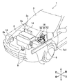
そして、パワープラント収納室2aの左右両側には、車両1の左右両側において前後方向に延設されるフロントサイドメンバ7が延伸している。
さらに、パワープラント2の上方には、収納室カバー2bとの間に空間が形成される。
一方、シリンダ本体82の、アクチュエータハウジング172側の端部も左右方向に広がってフランジ部820が形成され、このフランジ部820に、アクチュエータハウジング172のネジ孔176に対応する位置にシリンダ取付孔821が開口した構成とする。
そして、シリンダ本体82のフランジ部820とアクチュエータハウジング172のフランジ部175が対峙するように配置され、ボルトなどの締結部材822が、シリンダ本体82側からシリンダ取付孔821を介してネジ孔176にねじ込まれて、シリンダ本体82がアクチュエータハウジング172に締結固定される。
そして、図示しない出力軸に取り付けられた第1ギヤ78a(図1参照)が第1ギヤ室172bに収納されて第2ギヤ78bと噛合するように、電動モータ72が前方からアクチュエータハウジング172に取り付けられる。
例えば、モータケーシング72aは、アクチュエータハウジング172側の端部が周囲に広がってフランジ部161が形成され、このフランジ部161に、ボルトなどの締結部材162aが貫通するモータ取付孔162が開口した構成とする。
また、アクチュエータハウジング172は、モータ取付孔162に対応する位置にネジ孔174が開口した構成とする。
そして、電動モータ72は、第1ギヤ78a(図1参照)が取り付けられている出力軸(図示せず)がシリンダ本体82の軸方向と略平行になり、かつ、第1ギヤ78aが第1ギヤ室172bに収納されて第2ギヤ78b(図1参照)と噛合するように、前方(シリンダ本体82が連結されている側と同じ側)からアクチュエータハウジング172に取り付けられる。さらに、締結部材162aが、電動モータ72側からモータ取付孔162を介してネジ孔174にねじ込まれ、モータケーシング72aがアクチュエータハウジング172に締結固定される。
このように、本実施形態に係るモータシリンダ装置16は、アクチュエータハウジング172にシリンダ本体82が連結し、さらに、シリンダ本体82の下部に配置されるように電動モータ72が取り付けられて構成される。
一例として、図5に示すように形成されるブラケット2a1にモータシリンダ装置16が取り付けられる構造とすればよい。
また、ブラケット2a1は、前方から見て上方が開いた略コ字状を呈し、シリンダ本体82の固定用ボス82aを左右方向から挟持するように構成される。さらに、固定用ボス82aのねじ孔82a1に対応する位置に切欠部(又は貫通孔)200が形成される構成とする。
そして、ボルト等の締結部材201がブラケット2a1の切欠部(又は貫通孔)200を通って、挟持される固定用ボス82aのねじ孔82a1に緩衝部材202等を介してねじ込まれ、締結部材201によってモータシリンダ装置16がブラケット2a1に固定される構造とすればよい。
シリンダ本体82に形成される固定用ボス82aの数は限定するものではなく、片側に2つ以上の固定用ボス82aが形成される構成であってもよい。
なお、ブラケット2a1は、例えば下部が前方に延伸して電動モータ72の下方に配置され、アンダガード9が形成される構成が好ましい。
また、符号72bは、電動モータ72に電気信号を供給するための電気ケーブルである。
前記したように、パワープラント2と収納室カバー2bの間には空間が形成されることからシリンダ本体82はこの空間に配置され、シリンダ本体82とパワープラント2と収納室カバー2bの干渉を回避できる。
このように、本実施形態に係るモータシリンダ装置16は、デッドスペースとなりやすい空間にシリンダ本体82の少なくとも一部が配置され、モータシリンダ装置16をスペース効率よくパワープラント収納室2a内に配置できる。
この構成によると、例えば、モータシリンダ装置16の電動モータ72による下方への突出量を小さくすることができ、パワープラント2の上方で収納室カバー2b(図2参照)との間に形成される車両上下方向の空間が小さい場合でも、その空間にモータシリンダ装置16を配置できる。
このことによっても、モータシリンダ装置16をスペース効率よくパワープラント収納室2a内に配置できる。
この構成によって、パワープラント2の上方に形成される空間を有効に利用することができ、パワープラント収納室2aにモータシリンダ装置16がスペース効率よく配置される。また、シリンダ本体82をパワープラント収納室2aに配設するときの作業性を向上できる。
また、重量の重い電動モータ72がシリンダ本体82の下部に配置されることから、モータシリンダ装置16を安定した状態にして、パワープラント収納室2aに配設される。
2 パワープラント(車両動力装置)
2a パワープラント収納室(収納室)
2a1 ブラケット
7 フロントサイドメンバ
9 アンダガード(ガード部材)
10 車両用ブレーキシステム
12 ブレーキペダル(ブレーキ操作部)
14 入力装置
16 モータシリンダ装置(電動ブレーキアクチュエータ)
72 電動モータ
72a モータケーシング
82 シリンダ本体
88a 第1スレーブピストン(液圧制御ピストン)
88b 第2スレーブピストン(液圧制御ピストン)
Claims (4)
- 操作者のブレーキ操作が入力される入力装置と、
シリンダ本体に収納される液圧制御ピストンを少なくとも前記ブレーキ操作に応じて電動モータで駆動してブレーキ液圧を発生させる電動ブレーキアクチュエータと、が車両に備わって構成される車両用ブレーキシステムであって、
前記電動モータが、前記シリンダ本体の下部に配置され、
前記車両の走行で跳ね上げられた物体から前記電動モータを保護するガード部材が、前記電動ブレーキアクチュエータを前記車両に取り付けるブラケットと一体に形成されて備わっていることを特徴とする車両用ブレーキシステム。 - 前記電動モータが、前記液圧制御ピストンの軸線に対して左右方向にオフセットされて配置されることを特徴とする請求項1に記載の車両用ブレーキシステム。
- 前記電動モータは前記車両の左右両側において前後方向に延設されるフロントサイドメンバの間に配置される車両動力装置と、前記フロントサイドメンバとの間に配置されることを特徴とする請求項2に記載の車両用ブレーキシステム。
- 前記液圧制御ピストンの軸方向と出力軸が略平行になるように前記電動ブレーキアクチュエータに備わる前記電動モータが、前記液圧制御ピストンの軸線を中心として、前記車両動力装置から離れる方向にオフセットされて配置されることを特徴とする請求項3に記載の車両用ブレーキシステム。
Priority Applications (1)
| Application Number | Priority Date | Filing Date | Title |
|---|---|---|---|
| JP2012544305A JP5698258B2 (ja) | 2010-11-17 | 2011-11-17 | 車両用ブレーキシステム |
Applications Claiming Priority (4)
| Application Number | Priority Date | Filing Date | Title |
|---|---|---|---|
| JP2010257366 | 2010-11-17 | ||
| JP2010257366 | 2010-11-17 | ||
| PCT/JP2011/076567 WO2012067198A1 (ja) | 2010-11-17 | 2011-11-17 | 車両用ブレーキシステム |
| JP2012544305A JP5698258B2 (ja) | 2010-11-17 | 2011-11-17 | 車両用ブレーキシステム |
Publications (2)
| Publication Number | Publication Date |
|---|---|
| JPWO2012067198A1 JPWO2012067198A1 (ja) | 2014-05-19 |
| JP5698258B2 true JP5698258B2 (ja) | 2015-04-08 |
Family
ID=46084119
Family Applications (1)
| Application Number | Title | Priority Date | Filing Date |
|---|---|---|---|
| JP2012544305A Active JP5698258B2 (ja) | 2010-11-17 | 2011-11-17 | 車両用ブレーキシステム |
Country Status (5)
| Country | Link |
|---|---|
| US (1) | US9758143B2 (ja) |
| EP (1) | EP2641795B1 (ja) |
| JP (1) | JP5698258B2 (ja) |
| CN (1) | CN103221282B (ja) |
| WO (1) | WO2012067198A1 (ja) |
Families Citing this family (10)
| Publication number | Priority date | Publication date | Assignee | Title |
|---|---|---|---|---|
| EP2626262B1 (en) * | 2010-10-04 | 2015-04-29 | Honda Motor Co., Ltd. | Slave cylinder |
| US9233677B2 (en) * | 2010-11-17 | 2016-01-12 | Honda Motor Co., Ltd. | Vehicle brake system |
| WO2012067032A1 (ja) * | 2010-11-17 | 2012-05-24 | 本田技研工業株式会社 | 車両用ブレーキシステム |
| JP6088372B2 (ja) * | 2013-07-04 | 2017-03-01 | 本田技研工業株式会社 | 車両用ブレーキシステム |
| JP6194284B2 (ja) * | 2014-06-20 | 2017-09-06 | 本田技研工業株式会社 | 電動ブレーキアクチュエータ |
| US10507817B2 (en) * | 2014-11-04 | 2019-12-17 | Hitachi Automotive Systems, Ltd. | Electric motor-driven booster |
| FR3044992B1 (fr) * | 2015-12-15 | 2019-05-31 | Foundation Brakes France | Procede de commande d'un systeme de freinage apte a realiser la fonction frein de parking |
| JP6719255B2 (ja) * | 2016-03-30 | 2020-07-08 | 日信ブレーキシステムズ株式会社 | 液圧発生装置 |
| EP4067127B1 (en) * | 2021-03-31 | 2024-06-19 | BeijingWest Industries Co. Ltd. | Suspension hydraulic lift actuator for axle trim height control |
| DE102022121745A1 (de) * | 2022-08-29 | 2024-02-29 | Audi Aktiengesellschaft | Baugruppe eines Bremssystems |
Citations (3)
| Publication number | Priority date | Publication date | Assignee | Title |
|---|---|---|---|---|
| JPH09175376A (ja) * | 1995-12-28 | 1997-07-08 | Nissin Kogyo Kk | 電動式ブレーキ倍力装置 |
| JP2007084041A (ja) * | 2005-08-22 | 2007-04-05 | Mazda Motor Corp | マスターシリンダー前端部構造 |
| JP2009202867A (ja) * | 2008-01-31 | 2009-09-10 | Hitachi Ltd | 電動倍力装置 |
Family Cites Families (25)
| Publication number | Priority date | Publication date | Assignee | Title |
|---|---|---|---|---|
| US2209477A (en) * | 1938-11-03 | 1940-07-30 | Gen Motors Corp | Resilient motor mount |
| JPS6058460U (ja) | 1983-09-29 | 1985-04-23 | アイシン精機株式会社 | 車両用アンチスキツド装置のアクチユエ−タ |
| US4586590A (en) * | 1985-02-04 | 1986-05-06 | General Motors Corporation | Adjustable vehicle brake proportioning system |
| US4756391A (en) * | 1987-07-06 | 1988-07-12 | General Motors Corporation | Brake system actuator with a return spring |
| JP2605504B2 (ja) * | 1991-05-24 | 1997-04-30 | 日産自動車株式会社 | エンジンの横置配置構造 |
| US5464187A (en) * | 1993-10-06 | 1995-11-07 | Kelsey-Hayes Company | Mounting bracket for an anti-lock brake/traction control system control valve |
| DE4433825C2 (de) * | 1994-09-22 | 1996-08-01 | Fichtel & Sachs Ag | Stelleinrichtung mit einer Kupplungslageregelung |
| JPH1035453A (ja) | 1996-07-25 | 1998-02-10 | Aisin Seiki Co Ltd | 自動車用制動液圧制御装置 |
| AU4481197A (en) * | 1996-09-17 | 1998-04-14 | Kelsey-Hayes Company | Mounting arrangement for supporting a hydraulic control unit of a vehicular braking system |
| JPH10181557A (ja) * | 1996-12-26 | 1998-07-07 | Akebono Brake Res & Dev Center Ltd | 液圧制御装置とそれを利用したブレーキ装置 |
| GB2362360B (en) * | 1997-07-14 | 2002-01-09 | Land Rover Group Ltd | Motor vehicle undertray assemblies |
| FR2782684B1 (fr) | 1998-08-28 | 2000-11-10 | Bosch Syst Freinage | Dispositif de freinage a assistance et regulation combinees |
| US6408974B1 (en) * | 1999-06-10 | 2002-06-25 | International Truck Intellectual Property Company, L.L.C. | Component mount for a vehicle frame |
| IT1314620B1 (it) * | 2000-04-11 | 2002-12-20 | Mb Production Di Morini Antone | Strumento per chiamare tre numeri telefonici utili |
| US20050082134A1 (en) | 2000-04-11 | 2005-04-21 | Automac Engineering Srl | Electric actuators for clutch and/or sequential gearbox operation in motor vehicles |
| JP4654547B2 (ja) | 2001-07-24 | 2011-03-23 | トヨタ自動車株式会社 | ブレーキ装置 |
| US6574959B2 (en) * | 2001-08-02 | 2003-06-10 | Delphi Technologies, Inc. | Electric brake booster with unrestricted manual push through |
| US7063393B2 (en) * | 2001-08-22 | 2006-06-20 | Advics Co., Ltd. | Electronic brake system without pump unit |
| US6662915B2 (en) * | 2002-03-01 | 2003-12-16 | Textron Inc. | Hydraulic park brake booster mechanism |
| JP4999416B2 (ja) * | 2006-10-02 | 2012-08-15 | 本田技研工業株式会社 | ブレーキ装置 |
| DE102007018469A1 (de) * | 2007-04-19 | 2008-10-23 | Robert Bosch Gmbh | Elektromechanischer Bremskraftverstärker |
| JP5065955B2 (ja) | 2008-03-24 | 2012-11-07 | 日立オートモティブシステムズ株式会社 | ブレーキ制御システム |
| JP2010023594A (ja) | 2008-07-16 | 2010-02-04 | Nissan Motor Co Ltd | 電動倍力装置 |
| IT1392621B1 (it) * | 2008-10-23 | 2012-03-16 | Ferrari Spa | Impianto frenante di un veicolo atto a comandare una frenata rigenerativa |
| US8801110B2 (en) | 2009-02-13 | 2014-08-12 | Honda Motor Co., Ltd. | Vehicle brake device |
-
2011
- 2011-11-17 JP JP2012544305A patent/JP5698258B2/ja active Active
- 2011-11-17 EP EP11842182.5A patent/EP2641795B1/en active Active
- 2011-11-17 CN CN201180055202.0A patent/CN103221282B/zh active Active
- 2011-11-17 US US13/988,179 patent/US9758143B2/en active Active
- 2011-11-17 WO PCT/JP2011/076567 patent/WO2012067198A1/ja not_active Ceased
Patent Citations (3)
| Publication number | Priority date | Publication date | Assignee | Title |
|---|---|---|---|---|
| JPH09175376A (ja) * | 1995-12-28 | 1997-07-08 | Nissin Kogyo Kk | 電動式ブレーキ倍力装置 |
| JP2007084041A (ja) * | 2005-08-22 | 2007-04-05 | Mazda Motor Corp | マスターシリンダー前端部構造 |
| JP2009202867A (ja) * | 2008-01-31 | 2009-09-10 | Hitachi Ltd | 電動倍力装置 |
Also Published As
| Publication number | Publication date |
|---|---|
| WO2012067198A1 (ja) | 2012-05-24 |
| EP2641795A1 (en) | 2013-09-25 |
| CN103221282B (zh) | 2016-08-10 |
| JPWO2012067198A1 (ja) | 2014-05-19 |
| US9758143B2 (en) | 2017-09-12 |
| EP2641795B1 (en) | 2016-03-16 |
| US20130232968A1 (en) | 2013-09-12 |
| CN103221282A (zh) | 2013-07-24 |
| EP2641795A4 (en) | 2014-04-30 |
Similar Documents
| Publication | Publication Date | Title |
|---|---|---|
| JP5698258B2 (ja) | 車両用ブレーキシステム | |
| JP5688097B2 (ja) | 車両用ブレーキシステム | |
| JP5379112B2 (ja) | 電動ブレーキアクチュエータ | |
| JP5756527B2 (ja) | 制動装置 | |
| JP5840142B2 (ja) | 車両用ブレーキシステム | |
| JP5369077B2 (ja) | 電動ブレーキアクチュエータ取付構造 | |
| JP5432880B2 (ja) | 車両用ブレーキシステム | |
| JP5149953B2 (ja) | 車両用ブレーキシステムの入力装置 | |
| JP5200092B2 (ja) | 車両用ブレーキシステム及びその入力装置 | |
| JP2012106648A (ja) | 車両用ブレーキシステム | |
| JP5337133B2 (ja) | 車両用ブレーキシステム | |
| JP5364077B2 (ja) | 車両用ブレーキシステムの入力装置 | |
| JP5364076B2 (ja) | 車両用ブレーキシステムの入力装置 | |
| JP5503625B2 (ja) | 電動ブレーキアクチュエータ及び車両用ブレーキシステム | |
| JP5715382B2 (ja) | 車両用ブレーキシステム | |
| JP2012214110A (ja) | 電動ブレーキ装置 | |
| JP5646965B2 (ja) | 車両用構造物搭載室の配置構造 | |
| JP5276646B2 (ja) | 車両用ブレーキシステムの入力装置 | |
| JP5537391B2 (ja) | 車両用ブレーキシステム及びその入力装置 | |
| JP2014104808A (ja) | 制動装置 | |
| JP5193268B2 (ja) | 電動ブレーキアクチュエータの車体取付構造 |
Legal Events
| Date | Code | Title | Description |
|---|---|---|---|
| A131 | Notification of reasons for refusal |
Free format text: JAPANESE INTERMEDIATE CODE: A131 Effective date: 20140819 |
|
| A521 | Request for written amendment filed |
Free format text: JAPANESE INTERMEDIATE CODE: A523 Effective date: 20141020 |
|
| TRDD | Decision of grant or rejection written | ||
| A01 | Written decision to grant a patent or to grant a registration (utility model) |
Free format text: JAPANESE INTERMEDIATE CODE: A01 Effective date: 20150203 |
|
| A61 | First payment of annual fees (during grant procedure) |
Free format text: JAPANESE INTERMEDIATE CODE: A61 Effective date: 20150212 |
|
| R150 | Certificate of patent or registration of utility model |
Ref document number: 5698258 Country of ref document: JP Free format text: JAPANESE INTERMEDIATE CODE: R150 |