JP5779625B2 - 工作物表面を走査する方法および接触感知プローブ - Google Patents
工作物表面を走査する方法および接触感知プローブ Download PDFInfo
- Publication number
- JP5779625B2 JP5779625B2 JP2013187395A JP2013187395A JP5779625B2 JP 5779625 B2 JP5779625 B2 JP 5779625B2 JP 2013187395 A JP2013187395 A JP 2013187395A JP 2013187395 A JP2013187395 A JP 2013187395A JP 5779625 B2 JP5779625 B2 JP 5779625B2
- Authority
- JP
- Japan
- Prior art keywords
- stylus
- probe
- compliant member
- longitudinal axis
- mass
- Prior art date
- Legal status (The legal status is an assumption and is not a legal conclusion. Google has not performed a legal analysis and makes no representation as to the accuracy of the status listed.)
- Expired - Fee Related
Links
- 239000000523 sample Substances 0.000 title claims description 84
- 238000000034 method Methods 0.000 title claims description 23
- 241001422033 Thestylus Species 0.000 claims description 64
- 239000007787 solid Substances 0.000 claims description 3
- 239000000463 material Substances 0.000 claims 2
- 230000000694 effects Effects 0.000 description 5
- 238000002955 isolation Methods 0.000 description 4
- 238000005259 measurement Methods 0.000 description 4
- 230000008569 process Effects 0.000 description 3
- 238000005452 bending Methods 0.000 description 2
- 230000008859 change Effects 0.000 description 2
- 230000006835 compression Effects 0.000 description 2
- 238000007906 compression Methods 0.000 description 2
- 238000013016 damping Methods 0.000 description 2
- 238000004519 manufacturing process Methods 0.000 description 2
- 230000002238 attenuated effect Effects 0.000 description 1
- 230000008901 benefit Effects 0.000 description 1
- 230000008602 contraction Effects 0.000 description 1
- 230000008878 coupling Effects 0.000 description 1
- 238000010168 coupling process Methods 0.000 description 1
- 238000005859 coupling reaction Methods 0.000 description 1
- 238000001514 detection method Methods 0.000 description 1
- 238000010586 diagram Methods 0.000 description 1
- 230000007246 mechanism Effects 0.000 description 1
- 238000012544 monitoring process Methods 0.000 description 1
- 230000035945 sensitivity Effects 0.000 description 1
- 239000002893 slag Substances 0.000 description 1
Images



Classifications
-
- G—PHYSICS
- G01—MEASURING; TESTING
- G01B—MEASURING LENGTH, THICKNESS OR SIMILAR LINEAR DIMENSIONS; MEASURING ANGLES; MEASURING AREAS; MEASURING IRREGULARITIES OF SURFACES OR CONTOURS
- G01B7/00—Measuring arrangements characterised by the use of electric or magnetic techniques
- G01B7/004—Measuring arrangements characterised by the use of electric or magnetic techniques for measuring coordinates of points
- G01B7/008—Measuring arrangements characterised by the use of electric or magnetic techniques for measuring coordinates of points using coordinate measuring machines
- G01B7/012—Contact-making feeler heads therefor
Landscapes
- Physics & Mathematics (AREA)
- General Physics & Mathematics (AREA)
- Length Measuring Devices With Unspecified Measuring Means (AREA)
- A Measuring Device Byusing Mechanical Method (AREA)
- Measurement Of Length, Angles, Or The Like Using Electric Or Magnetic Means (AREA)
Description
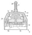
図1、5を参照すると、本発明のプローブ2が示されている。
プローブ2は、座標位置決め機への装着に適したプローブ本体4を備える。本実施例において、プローブ2は、携帯型連接測定アームへの装着に適した手動走査プローブである。プローブ2は、解放可能に取り付け可能なスタイラス6、および駆動回路10によって駆動される圧電スタック(piezo−electric stack)8の形の変換器を備える。この構成によってスタイラス6が必要振動数で長手方向に振動することができるようになる。
4 プローブ本体
6 スタイラス
8 圧電スタック
14,16 ダイヤフラム
Claims (20)
- 座標位置決め機内に装着された接触感知プローブを使用して工作物表面を走査する方法であって、
前記プローブは、プローブ本体と、長手方向軸を有する物体接触スタイラスと、前記プローブ本体内の前記スタイラス用の装着物と、前記スタイラスを前記長手方向に振動させるために前記スタイラスに機械的に結合された変換器とを備え、前記装着物は、前記長手方向軸を横切る方向において堅く、前記長手方向軸の周りで均一な横方向堅さを有し、
前記方法が、
(A)前記工作物表面と前記スタイラスを接触させるステップ、
(B)前記工作物表面と前記スタイラスの間の接触を維持しながら、前記表面を走査するステップであって、前記装着物が前記横方向において堅いため、走査中における前記工作物表面との横方向の接触力の結果として前記プローブの変形がわずかであるステップ、
(C)前記スタイラスの振動から、前記走査中に接触が引き続き維持されていることを検出するステップ、および
(D)前記(C)ステップで決定されたとおりに前記接触が引き続き維持されている間、前記座標位置決め機に前記工作物表面の一連の連続座標読み取りをおこなわせるステップ
を含むことを特徴とする方法。 - 前記装着物は、前記長手方向軸に関して円形対称の横方向堅さを有することを特徴とする請求項1に記載の方法。
- 前記(A)ステップは、前記工作物表面と前記スタイラスを横方向に接触させることを含み、前記(B)ステップは、前記工作物表面と前記スタイラスの間の接触を横方向に維持しながら、前記工作物表面を走査することを含むことを特徴とする請求項1または2に記載の方法。
- 前記装着物は、前記長手方向軸を横切る2つの直交する前記方向において堅いことを特徴とする請求項1〜3のいずれか一項に記載の方法。
- 前記装着物は、マスと、コンプライアント部材と、前記マスおよび前記スタイラスの間に装着される変換器とを備えることを特徴とする請求項1〜4のいずれか一項に記載の方法。
- 前記マスと前記コンプライアント部材は、前記プローブ本体と前記スタイラスの間に直列に接続され、前記マスは、前記スタイラスと前記コンプライアント部材の間に接続されていることを特徴とする請求項5に記載の方法。
- 前記マスと、前記コンプライアント部材とは、前記スタイラスの振動を前記プローブ本体から機械的に隔離するための手段を形成するよう、配置されていることを特徴とする請求項5または6に記載の方法。
- 前記スタイラスを隔離するための前記手段は、機械的な低域通過フィルタを形成することを特徴とする請求項7に記載の方法。
- 前記コンプライアント部材は、可撓性ダイヤフラムを備えることを特徴とする請求項5〜8のいずれか一項に記載の方法。
- 前記可撓性ダイヤフラムは、前記長手方向軸に関して半径方向または回転方向に対称であることを特徴とする請求項9に記載の方法。
- 前記可撓性ダイヤフラムは、前記長手方向軸に関して円形対称であることを特徴とする請求項10に記載の方法。
- 前記可撓性ダイヤフラムは、ディスク形状であることを特徴とする請求項10または11に記載の方法。
- 前記装着物は、追加のコンプライアント部材を備え、前記追加のコンプライアント部材は、前記スタイラスと前記マスおよび前記変換器の少なくとも一方との間に設けられていることを特徴とする請求項5〜12のいずれか一項に記載の方法。
- 前記マスと、前記コンプライアント部材および前記追加のコンプライアント部材とは、前記スタイラスの振動を前記プローブ本体から機械的に隔離するための手段を形成するよう、配置されていることを特徴とする請求項13に記載の方法。
- 前記座標位置決め機は、手動測定機、座標測定機および工作機械から選択されることを特徴とする請求項1〜14のいずれか一項に記載の方法。
- 座標位置決め機のための接触感知プローブであって、プローブ本体と、長手方向軸を有する物体接触スタイラスと、前記プローブ本体内の前記スタイラス用の装着物と、前記スタイラスを前記長手方向に振動させるために前記スタイラスに機械的に結合された変換器とを備え、前記装着物は、前記長手方向軸を横切る方向において堅く、前記長手方向軸の周りで均一な横方向堅さを有し、前記装着物は、前記プローブが、前記スタイラスの前記長手方向軸に対して横方向でほぼ剛直であり、前記プローブが走査中に曲がらないよう、構成されていることを特徴とする接触感知プローブ。
- 前記装着物はコンプライアント部材を備え、前記コンプライアント部材は可撓性ダイヤフラムを備え、前記可撓性ダイヤフラムは完全中実ディスクを備えることを特徴とする請求項16に記載の接触感知プローブ。
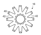
- 前記装着物は、コンプライアント部材と別のコンプライアント部材とを備え、前記コンプライアント部材は、完全中実ディスクを備える可撓性ダイヤフラムを備え、前記別のコンプライアント部材は、スポーク形状を有する別の可撓性ダイヤフラムを備えることを特徴とする請求項16に記載の接触感知プローブ。
- 前記装着物は、前記長手方向軸に関して円形対称の横方向堅さを有することを特徴とする請求項16〜18のいずれか一項に記載の接触感知プローブ。
- 請求項16〜19のいずれか一項に記載の接触感知プローブを備えたことを特徴とする座標位置決め機。
Applications Claiming Priority (2)
| Application Number | Priority Date | Filing Date | Title |
|---|---|---|---|
| GB0608998.1 | 2006-05-08 | ||
| GBGB0608998.1A GB0608998D0 (en) | 2006-05-08 | 2006-05-08 | Contact sensing probe |
Related Parent Applications (1)
| Application Number | Title | Priority Date | Filing Date |
|---|---|---|---|
| JP2009508478A Division JP2009536337A (ja) | 2006-05-08 | 2007-05-08 | 接触感知プローブ |
Publications (2)
| Publication Number | Publication Date |
|---|---|
| JP2014006262A JP2014006262A (ja) | 2014-01-16 |
| JP5779625B2 true JP5779625B2 (ja) | 2015-09-16 |
Family
ID=36604073
Family Applications (2)
| Application Number | Title | Priority Date | Filing Date |
|---|---|---|---|
| JP2009508478A Pending JP2009536337A (ja) | 2006-05-08 | 2007-05-08 | 接触感知プローブ |
| JP2013187395A Expired - Fee Related JP5779625B2 (ja) | 2006-05-08 | 2013-09-10 | 工作物表面を走査する方法および接触感知プローブ |
Family Applications Before (1)
| Application Number | Title | Priority Date | Filing Date |
|---|---|---|---|
| JP2009508478A Pending JP2009536337A (ja) | 2006-05-08 | 2007-05-08 | 接触感知プローブ |
Country Status (6)
| Country | Link |
|---|---|
| US (1) | US7856731B2 (ja) |
| EP (1) | EP2027429A1 (ja) |
| JP (2) | JP2009536337A (ja) |
| CN (1) | CN101443627B (ja) |
| GB (1) | GB0608998D0 (ja) |
| WO (1) | WO2007129082A1 (ja) |
Families Citing this family (9)
| Publication number | Priority date | Publication date | Assignee | Title |
|---|---|---|---|---|
| GB0609022D0 (en) * | 2006-05-08 | 2006-06-14 | Renishaw Plc | Contact sensing probe |
| GB0708319D0 (en) | 2007-04-30 | 2007-06-06 | Renishaw Plc | A storage apparatus for a tool |
| US8919005B2 (en) | 2007-04-30 | 2014-12-30 | Renishaw Plc | Analogue probe and method of operation |
| GB201007186D0 (en) | 2010-04-30 | 2010-06-09 | Renishaw Plc | Changeable task module counterweight |
| DE102012018417B4 (de) * | 2012-09-12 | 2015-04-23 | Hans-Holger Anger | Tasteinrichtung und Messeinrichtung mit einer derartigen Tasteinrichtung |
| JP6122312B2 (ja) | 2013-02-28 | 2017-04-26 | 株式会社ミツトヨ | 形状測定機 |
| US9377282B2 (en) | 2013-09-03 | 2016-06-28 | Mitutoyo Corporation | Method for validating a workpiece measurement in a dimensional metrology hand tool |
| WO2018204663A1 (en) | 2017-05-04 | 2018-11-08 | CTRL Systems Inc. | Piezoelectric vibration sensor |
| CN110285759B (zh) * | 2019-08-01 | 2021-01-12 | 台州市肯创机械设备有限公司 | 一种高灵敏性三坐标测量机探测机构 |
Family Cites Families (32)
| Publication number | Priority date | Publication date | Assignee | Title |
|---|---|---|---|---|
| GB2006435B (en) | 1977-10-22 | 1982-09-22 | Renishaw Electrical Ltd | Contact-sensing probe |
| GB2070249A (en) | 1980-02-21 | 1981-09-03 | Rank Organisation Ltd | Contact-sensitive probe |
| DE3215878A1 (de) * | 1982-04-29 | 1983-11-03 | Fa. Carl Zeiss, 7920 Heidenheim | Tastkopf fuer koordinatenmessgeraete |
| US4625417A (en) * | 1985-06-17 | 1986-12-02 | Gte Valeron Corporation | Probe with stylus pressure adjustment |
| GB8815984D0 (en) * | 1988-07-05 | 1988-08-10 | Univ Brunel | Probes |
| US5209131A (en) * | 1989-11-03 | 1993-05-11 | Rank Taylor Hobson | Metrology |
| US5247751A (en) | 1990-09-29 | 1993-09-28 | Nikon Corporation | Touch probe |
| US5247551A (en) | 1991-09-24 | 1993-09-21 | Siemens Power Corporation | Spacer sleeve for nuclear fuel assembly |
| JPH0792373B2 (ja) * | 1991-09-25 | 1995-10-09 | 株式会社ミツトヨ | タッチ信号プローブ |
| JP2966214B2 (ja) * | 1992-11-05 | 1999-10-25 | キヤノン株式会社 | 表面形状計測装置 |
| US5611147A (en) | 1993-02-23 | 1997-03-18 | Faro Technologies, Inc. | Three dimensional coordinate measuring apparatus |
| GB9423176D0 (en) * | 1994-11-17 | 1995-01-04 | Renishaw Plc | Touch probe |
| JP3459710B2 (ja) * | 1995-09-29 | 2003-10-27 | キヤノン株式会社 | 触針式プローブ |
| JPH10281751A (ja) * | 1997-04-07 | 1998-10-23 | Kett Electric Lab | 厚み測定器のプローブ |
| JP3197860B2 (ja) | 1997-12-24 | 2001-08-13 | 株式会社ミツトヨ | タッチ信号プローブ |
| JP3815910B2 (ja) * | 1998-12-28 | 2006-08-30 | 株式会社牧野フライス製作所 | 測定ヘッド及び測定フィーラ |
| GB9907643D0 (en) * | 1999-04-06 | 1999-05-26 | Renishaw Plc | Measuring probe |
| JP3650555B2 (ja) * | 1999-09-27 | 2005-05-18 | 株式会社ミツトヨ | タッチセンサ |
| JP3650556B2 (ja) * | 1999-09-27 | 2005-05-18 | 株式会社ミツトヨ | タッチセンサ |
| JP3819250B2 (ja) * | 2000-05-15 | 2006-09-06 | 株式会社ミツトヨ | 加振型接触検出センサ |
| DE10101925B4 (de) * | 2001-01-16 | 2006-08-24 | Dr. Johannes Heidenhain Gmbh | Taststift |
| DE10108774A1 (de) * | 2001-02-23 | 2002-09-05 | Zeiss Carl | Koordinatenmessgerät zum Antasten eines Werkstücks, Tastkopf für ein Koordinatenmessgerät und Verfahren zum Betrieb eines Koordinatenmessgerätes |
| JP3818881B2 (ja) * | 2001-08-29 | 2006-09-06 | 株式会社ミツトヨ | 接触型センサ |
| JP4179774B2 (ja) * | 2001-11-21 | 2008-11-12 | 株式会社ミツトヨ | 加振型接触検出センサ |
| EP1478898B1 (de) * | 2002-02-28 | 2006-07-05 | Carl Zeiss Industrielle Messtechnik GmbH | Tastkopf für koordinaten-messgeräte |
| JP3983637B2 (ja) * | 2002-09-20 | 2007-09-26 | 株式会社リコー | 触針式プローブ機構の制御方法及び装置 |
| JP2006504953A (ja) * | 2002-10-29 | 2006-02-09 | コーニンクレッカ フィリップス エレクトロニクス エヌ ヴィ | 振動減衰システムを備えた座標測定装置 |
| ATE339671T1 (de) * | 2003-01-31 | 2006-10-15 | Zeiss Ind Messtechnik Gmbh | Tastkopf für ein koordinatenmessgerät |
| JP2004271473A (ja) * | 2003-03-12 | 2004-09-30 | Yachiyo Industry Co Ltd | 雌ねじの内径測定装置 |
| JP4037306B2 (ja) * | 2003-03-31 | 2008-01-23 | 三井金属鉱業株式会社 | 圧力調整機構を備えた青果類の硬度測定装置および青果類の硬度測定方法 |
| GB0509394D0 (en) * | 2005-05-10 | 2005-06-15 | Renishaw Plc | Dimensional measurement probe |
| JP2009125853A (ja) * | 2007-11-22 | 2009-06-11 | Murata Mach Ltd | センサ |
-
2006
- 2006-05-08 GB GBGB0608998.1A patent/GB0608998D0/en not_active Ceased
-
2007
- 2007-05-08 CN CN2007800169107A patent/CN101443627B/zh not_active Expired - Fee Related
- 2007-05-08 EP EP07732705A patent/EP2027429A1/en not_active Withdrawn
- 2007-05-08 WO PCT/GB2007/001676 patent/WO2007129082A1/en not_active Ceased
- 2007-05-08 JP JP2009508478A patent/JP2009536337A/ja active Pending
- 2007-05-08 US US12/227,074 patent/US7856731B2/en not_active Expired - Fee Related
-
2013
- 2013-09-10 JP JP2013187395A patent/JP5779625B2/ja not_active Expired - Fee Related
Also Published As
| Publication number | Publication date |
|---|---|
| EP2027429A1 (en) | 2009-02-25 |
| JP2009536337A (ja) | 2009-10-08 |
| WO2007129082A1 (en) | 2007-11-15 |
| JP2014006262A (ja) | 2014-01-16 |
| GB0608998D0 (en) | 2006-06-14 |
| US7856731B2 (en) | 2010-12-28 |
| CN101443627A (zh) | 2009-05-27 |
| US20090100693A1 (en) | 2009-04-23 |
| CN101443627B (zh) | 2012-06-13 |
Similar Documents
| Publication | Publication Date | Title |
|---|---|---|
| JP5779625B2 (ja) | 工作物表面を走査する方法および接触感知プローブ | |
| EP2449353B1 (en) | Articulated arm system with vibration detection and corresponding operating method | |
| US6708420B1 (en) | Piezoelectric touch probe | |
| JP4594286B2 (ja) | 空気中のパラメトリック・トランスミッティング・アレイを用いた超指向性超音波距離測定のためのmemsに基づく多共振超音波トランスデューサ及びその製作方法 | |
| EP3211362B1 (en) | Measuring probe | |
| JPH0243121B2 (ja) | ||
| JP2018096987A (ja) | フラッシュメモリに記憶されたカウント値を持つ測定装置用トリガカウンタ | |
| WO2003019204A3 (en) | Sensor for non-contacting electrostatic detector | |
| KR102452076B1 (ko) | 진동 또는 음향 특성 분석에 기초한 웨이퍼 클램프 검출 | |
| JP2022541859A (ja) | 超音波測定ユニット | |
| WO2003019203A8 (en) | Sensor for non-contacting electrostatic detector | |
| JP4958305B2 (ja) | 装着具に設置されたセンサを備えた超音波トランスジューサ | |
| EP1893937B1 (en) | Touch probe with means for detecting orientation change | |
| EP0927867B1 (en) | Touch-signal probe | |
| JP2017037052A (ja) | 振動検出装置、振動検出方法および振動検出プログラム | |
| JP5260849B2 (ja) | タッチプローブ | |
| JP3140476U (ja) | 加振型接触検出センサ | |
| EP1851753B1 (en) | Self-supporting and self-aligning vibration excitator | |
| JPH10176902A (ja) | タッチ信号プローブ | |
| EP1095254A1 (en) | Surface testing equipment and method | |
| JPS6321582A (ja) | 超音波送受波器 | |
| JP2000292145A (ja) | タッチ信号プローブの動作制御構造 | |
| JPH0395406A (ja) | 接触検出機構及びその検出方法 | |
| CN116115119A (zh) | 一种触碰传感器结构及扫地机器人 | |
| WO2008056137A1 (en) | Connection interface for a measurement probe |
Legal Events
| Date | Code | Title | Description |
|---|---|---|---|
| A977 | Report on retrieval |
Free format text: JAPANESE INTERMEDIATE CODE: A971007 Effective date: 20140523 |
|
| A131 | Notification of reasons for refusal |
Free format text: JAPANESE INTERMEDIATE CODE: A131 Effective date: 20140603 |
|
| A521 | Request for written amendment filed |
Free format text: JAPANESE INTERMEDIATE CODE: A523 Effective date: 20140902 |
|
| A131 | Notification of reasons for refusal |
Free format text: JAPANESE INTERMEDIATE CODE: A131 Effective date: 20141111 |
|
| A521 | Request for written amendment filed |
Free format text: JAPANESE INTERMEDIATE CODE: A523 Effective date: 20150212 |
|
| TRDD | Decision of grant or rejection written | ||
| A01 | Written decision to grant a patent or to grant a registration (utility model) |
Free format text: JAPANESE INTERMEDIATE CODE: A01 Effective date: 20150616 |
|
| A61 | First payment of annual fees (during grant procedure) |
Free format text: JAPANESE INTERMEDIATE CODE: A61 Effective date: 20150713 |
|
| R150 | Certificate of patent or registration of utility model |
Ref document number: 5779625 Country of ref document: JP Free format text: JAPANESE INTERMEDIATE CODE: R150 |
|
| LAPS | Cancellation because of no payment of annual fees |