JP6834092B2 - Dielectric composition and multilayer ceramic capacitors containing it - Google Patents
Dielectric composition and multilayer ceramic capacitors containing it Download PDFInfo
- Publication number
- JP6834092B2 JP6834092B2 JP2016152257A JP2016152257A JP6834092B2 JP 6834092 B2 JP6834092 B2 JP 6834092B2 JP 2016152257 A JP2016152257 A JP 2016152257A JP 2016152257 A JP2016152257 A JP 2016152257A JP 6834092 B2 JP6834092 B2 JP 6834092B2
- Authority
- JP
- Japan
- Prior art keywords
- mol
- dielectric
- subcomponent
- multilayer ceramic
- dielectric composition
- Prior art date
- Legal status (The legal status is an assumption and is not a legal conclusion. Google has not performed a legal analysis and makes no representation as to the accuracy of the status listed.)
- Active
Links
Images

Landscapes
- Engineering & Computer Science (AREA)
- Power Engineering (AREA)
- Chemical & Material Sciences (AREA)
- Ceramic Engineering (AREA)
- Manufacturing & Machinery (AREA)
- Microelectronics & Electronic Packaging (AREA)
- Inorganic Chemistry (AREA)
- Compositions Of Oxide Ceramics (AREA)
- Ceramic Capacitors (AREA)
- Fixed Capacitors And Capacitor Manufacturing Machines (AREA)
- Inorganic Insulating Materials (AREA)
Description
本発明は、X5R、X7R及びX8Rの温度特性を満たし、信頼性が向上可能な新規の誘電体組成物及びこれを含む積層セラミックキャパシタに関する。 The present invention relates to a novel dielectric composition that satisfies the temperature characteristics of X5R, X7R and X8R and can improve reliability, and a multilayer ceramic capacitor containing the same.
最近、映像機器の大型化、コンピューターのCPU速度の上昇などによって、電子機器の発熱が深刻となっており、IC(Integrated Circuit;集積回路)の安定した動作のために、高い温度で安定した容量と信頼性が確保できるX5R(−55℃〜85℃まで動作温度)またはX7R(−25℃〜125℃まで動作温度)、さらにはX8R(−55℃〜150℃)級の機種に対する市場の要求が高まっている。 Recently, due to the increase in size of video equipment and the increase in CPU speed of computers, heat generation of electronic equipment has become serious, and stable capacity at high temperature for stable operation of IC (Integrated Circuit). Market demand for X5R (operating temperature from -55 ° C to 85 ° C) or X7R (operating temperature from -25 ° C to 125 ° C), and X8R (-55 ° C to 150 ° C) class models that can ensure reliability Is increasing.
これと共に、一般的な電子製品市場の傾向である小型軽量化、多機能化に符合するために、積層セラミックキャパシタ(MLCC)チップ製品の小型化、高容量化、昇圧化が継続的に要求されている。従って、誘電体層の薄層化と共に優れた耐電圧及びDC特性がX5R、X7RまたはX8R級の機種開発で重要に考慮されている。 At the same time, in order to meet the trend of smaller size, lighter weight, and higher functionality in the general electronic product market, the size, capacity, and boost of multilayer ceramic capacitor (MLCC) chip products are continuously required. ing. Therefore, excellent withstand voltage and DC characteristics are importantly considered in the development of X5R, X7R or X8R class models as well as the thinning of the dielectric layer.
薄層化、昇圧化は、誘電体層にかかる電界の強さを高めて、DC特性と耐電圧特性を悪化させる。特に、薄層化による微細構造上の欠陥がBDV(Breakdown Voltage)、高温IRなどの耐電圧特性に及ぶ影響をさらに深刻にする。 Thinning and boosting increase the strength of the electric field applied to the dielectric layer and deteriorate the DC characteristics and withstand voltage characteristics. In particular, the influence of microstructural defects due to thinning on the withstand voltage characteristics such as BDV (Breakdown Voltage) and high temperature IR becomes more serious.
本発明の目的の一つは、X5R、X7R及びX8Rの温度特性及び信頼性が向上可能な新規の誘電体組成物及びこれを含む積層セラミックキャパシタを提供することにある。 One of an object of the present invention is to provide a novel dielectric composition capable of improving the temperature characteristics and reliability of X5R, X7R and X8R, and a multilayer ceramic capacitor containing the same.
上述した目的を解決するために、本発明は、一実施形態で強誘電体と常誘電体を固有の組成式及び割合で含有する誘電体組成物を提供し、具体的に、(Ba,Ti)O3系列の強誘電体物質を第1主成分、(Ca,Sr)(Zr,Ti)O3系列の常誘電体物質を第2主成分とし、上記第1主成分のモル分率をa、上記第2主成分のモル分率をbとすると、0.33≦a/b≦3の条件を満たし、上記第2主成分は、組成式(Ca,Sr)(Zr1−xTix)O3で表され、ここで、xは、0.2≦x≦0.8の条件を満たす。 In order to solve the above-mentioned object, the present invention provides a dielectric composition containing a ferroelectric substance and a normal dielectric material in a unique composition formula and ratio in one embodiment, and specifically (Ba, Ti). ) O 3 series ferroelectric substance is the first main component, (Ca, Sr) (Zr, Ti) O 3 series ferroelectric substance is the second main component, and the mole fraction of the first main component is determined. Assuming that the mole fraction of the second main component is b, the condition of 0.33 ≦ a / b ≦ 3 is satisfied, and the second main component contains the composition formula (Ca, Sr) (Zr 1-x Ti). x) is represented by O 3, wherein, x is satisfies the condition of 0.2 ≦ x ≦ 0.8.
さらに、このような誘電体組成物を利用して積層セラミックキャパシタを具現することで、誘電特性、耐電圧特性などを向上させることができる。 Furthermore, by embodying a multilayer ceramic capacitor using such a dielectric composition, it is possible to improve the dielectric characteristics, withstand voltage characteristics, and the like.
本発明の一実施形態によると、誘電率が高く、耐電圧特性に優れた誘電体組成物及びこれを含む積層セラミックキャパシタを具現することができる。 According to one embodiment of the present invention, a dielectric composition having a high dielectric constant and excellent withstand voltage characteristics and a multilayer ceramic capacitor containing the dielectric composition can be realized.
以下では、添付の図面を参照し、本発明の好ましい実施形態について説明する。しかし、本発明の実施形態は様々な他の形態に変形されることができ、本発明の範囲は以下で説明する実施形態に限定されない。また、本発明の実施形態は、当該技術分野で平均的な知識を有する者に本発明をより完全に説明するために提供されるものである。したがって、図面における要素の形状及び大きさなどはより明確な説明のために誇張されることがあり、図面上において同一の符号で示される要素は同一の要素である。 Hereinafter, preferred embodiments of the present invention will be described with reference to the accompanying drawings. However, embodiments of the present invention can be transformed into various other embodiments, and the scope of the invention is not limited to the embodiments described below. In addition, embodiments of the present invention are provided to more fully explain the present invention to those having average knowledge in the art. Therefore, the shape and size of the elements in the drawings may be exaggerated for a clearer explanation, and the elements represented by the same reference numerals in the drawings are the same elements.
また、本発明を明確に説明すべく、説明と関係ない部分は省略し、多様の層及び領域を明確に表現するために厚さを拡大して示し、同一思想の範囲内において機能が同一である構成要素に対しては同一の参照符号を用いて説明する。さらに、明細書全体において、ある構成要素を「含む」というのは、特に反対される記載がない限り、他の構成要素を除外するのではなく、他の構成要素をさらに含むことができることを意味する。 In addition, in order to clearly explain the present invention, parts unrelated to the explanation are omitted, and the thickness is enlarged to clearly express various layers and regions, and the functions are the same within the scope of the same idea. The same reference code will be used for a certain component. Further, in the whole specification, "including" a component means that the other component may be further included rather than excluding the other component unless otherwise stated. To do.
本発明は、誘電体組成物に関し、誘電体組成物を含む電子部品は、キャパシタ、インダクター、圧電体素子、バリスタ、またはサーミスタなどがあり、以下では、誘電体組成物及び電子部品の一例として、積層セラミックキャパシタについて説明する。 The present invention relates to a dielectric composition, and electronic components containing the dielectric composition include capacitors, inductors, piezoelectric elements, varistor, thermistors, and the like. Hereinafter, as an example of the dielectric composition and electronic components, A multilayer ceramic capacitor will be described.
誘電体組成物
本発明の一実施形態による誘電体組成物は、(Ba,Ti)O3系列の強誘電体物質を第1主成分、(Ca,Sr)(Zr,Ti)O3系列の常誘電体物質を第2主成分とし、上記第1主成分のモル分率をa、上記第2主成分のモル分率をbとすると、0.33≦a/b≦3の条件を満たし、上記第2主成分は組成式(Ca,Sr)(Zr1−xTix)O3で表され、ここで、xは、0.2≦x≦0.8の条件を満たす。
Dielectric Composition The dielectric composition according to one embodiment of the present invention contains a (Ba, Ti) O 3 series ferroelectric substance as the first principal component, and (Ca, Sr) (Zr, Ti) O 3 series. Assuming that the ferroelectric substance is the second principal component, the mole fraction of the first principal component is a, and the mole fraction of the second principal component is b, the condition of 0.33 ≦ a / b ≦ 3 is satisfied. The second principal component is represented by the composition formula (Ca, Sr) (Zr 1-x Ti x ) O 3 , where x satisfies the condition of 0.2 ≦ x ≦ 0.8.
このような条件を満たす誘電体組成物は、EIA(Electronic Industries Association)規格で明示したX5R(−55℃〜85℃)、X7R(−55℃〜125℃)、そしてX8R(−55℃〜150℃)特性を満たすことができる。 Dielectric compositions satisfying such conditions are X5R (-55 ° C. to 85 ° C.), X7R (-55 ° C. to 125 ° C.), and X8R (-55 ° C. to 150 ° C.) specified in the EIA (Electronic Industries Association) standard. ℃) characteristics can be satisfied.
さらに詳しくは、本発明の一実施形態によると、ニッケル(Ni)を内部電極として使用し、1300℃以下で上記ニッケル(Ni)が酸化しない還元雰囲気で焼成が可能な誘電体組成物を提供する。また、これを利用した積層セラミックキャパシタを提供して上記温度特性を満たすと同時に、優れた信頼性を具現することができる。 More specifically, according to one embodiment of the present invention, there is provided a dielectric composition that uses nickel (Ni) as an internal electrode and can be fired in a reducing atmosphere in which the nickel (Ni) does not oxidize at 1300 ° C. or lower. .. Further, a multilayer ceramic capacitor utilizing this can be provided to satisfy the above temperature characteristics and at the same time realize excellent reliability.
以下、本発明の一実施形態による誘電体組成物の各成分をより具体的に説明する。 Hereinafter, each component of the dielectric composition according to the embodiment of the present invention will be described more specifically.
a)主成分
本発明の一実施形態による誘電体組成物の場合、(Ba,Ti)O3系列の強誘電体物質を第1主成分、(Ca,Sr)(Zr,Ti)O3系列の常誘電体物質を第2主成分とし、上記第1主成分のモル分率をa、上記第2主成分のモル分率をbとすると、0.33≦a/b≦3の条件を満たし、上記第2主成分は組成式(Ca,Sr)(Zr1−xTix)O3で表され、ここで、xは、0.2≦x≦0.8の条件を満たす。
a) Principal component In the case of the dielectric composition according to one embodiment of the present invention, the (Ba, Ti) O 3 series of ferroelectric substance is the first principal component, and (Ca, Sr) (Zr, Ti) O 3 series. Assuming that the ferroelectric substance of No. 2 is the second principal component, the mole fraction of the first principal component is a, and the mole fraction of the second principal component is b, the condition of 0.33 ≦ a / b ≦ 3 is satisfied. satisfied, the second principal component is represented by a composition formula (Ca, Sr) (Zr 1 -x Ti x) O 3, where, x is satisfies the condition of 0.2 ≦ x ≦ 0.8.
この場合、上記第1主成分は、BaTiO3、(Ba,Ca)(Ti,Ca)O3、(Ba,Ca)(Ti,Zr)O3、Ba(Ti,Zr)O3及び(Ba,Ca)(Ti,Sn)O3の少なくともいずれか一つの組成式で表されることができる。 In this case, the first principal components are BaTIO 3 , (Ba, Ca) (Ti, Ca) O 3 , (Ba, Ca) (Ti, Zr) O 3 , Ba (Ti, Zr) O 3 and (Ba). , Ca) (Ti, can be represented by a single formula, at least one of Sn) O 3.
MLCCの代表的な劣化モデルの一つである還元モデルによると、BaTiO3の基本構造で高い移動度を有する酸素空孔(void)が生成され、このような酸素空孔の移動によって劣化が発生すると知られている。即ち、酸素空孔が発生した状態で電場が印加されれば、酸素空孔はカソード側に移動して、カソードには酸素空孔の濃度勾配が形成され、アノードは酸素が放出されながら還元されて電子濃度が増加する。 According to the reduction model, which is one of the typical deterioration models of MLCC, oxygen voids having high mobility are generated in the basic structure of BaTiO 3, and deterioration occurs due to such movement of oxygen vacancies. Is known to be. That is, if an electric field is applied with oxygen vacancies generated, the oxygen vacancies move to the cathode side, a concentration gradient of oxygen vacancies is formed on the cathode, and the anode is reduced while oxygen is released. The electron concentration increases.
このように、酸素空孔の移動によって漏れ電流が増加し得るため、本発明の発明者は、酸素空孔の濃度を制御し、移動度を低くすることができる効果的な方法を導出しようとした。従来は、電子の濃度を低くするか、電子の移動を抑制するために、アクセプタドーパントの添加量を調節する方法を使用したが、これには、化学量論比を満たすことができず、欠陥が発生するなどの問題がある。 Since the leakage current can be increased by the movement of oxygen vacancies in this way, the inventor of the present invention has tried to derive an effective method capable of controlling the concentration of oxygen vacancies and reducing the mobility. did. Conventionally, a method of adjusting the amount of acceptor dopant added to reduce the electron concentration or suppress the movement of electrons has been used, but this cannot satisfy the stoichiometric ratio and is defective. There is a problem such as occurrence.
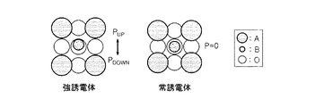
このような酸素空孔の発生と移動様相は、物質によって異なり、本発明の発明者らは、強誘電体と常誘電体の差異に注目した。図1は、強誘電体材料と常誘電体材料において、結晶構造及び配位原子との酸素結合状態を模式的に示したものである。図1において、A、B、Oは、ABO3結晶構造で各元素を表す。また、図2は、強誘電体材料と常誘電体材料において、温度による誘電特性の挙動を比較して示すグラフである。 The generation and movement of such oxygen vacancies differ depending on the substance, and the inventors of the present invention paid attention to the difference between the ferroelectric substance and the normal dielectric substance. FIG. 1 schematically shows the crystal structure and the oxygen bond state of the coordination atom in the ferroelectric material and the normal dielectric material. In FIG. 1, A, B, and O represent each element in the ABO 3 crystal structure. Further, FIG. 2 is a graph showing a comparison of the behavior of the dielectric property depending on the temperature between the ferroelectric material and the normal dielectric material.
図1を参照すると、先ず、BaTiO3等のような強誘電体物質の場合、温度による相変異とTc温度以下における格子変異により、体心に位置したTi陽イオン(Bに該当)と、その周りを配位している酸素陰イオン(Oに該当)との分極が形成される。このようにTi−O原子間の不安定な結合をしているため、強誘電体材料の場合、印加される電圧の方向によってより容易にTi−Oの結合構造が破壊されることができ、これにより、酸素空孔が生成され、移動度が増加する。 Referring to FIG. 1, first, in the case of a ferroelectric substance such as BaTiO 3 , the Ti cation (corresponding to B) located in the body center due to the phase variation due to temperature and the lattice variation below the Tc temperature, and its Polarization with oxygen anions (corresponding to O) coordinating the surroundings is formed. Since the Ti—O atoms are unstablely bonded in this way, in the case of a ferroelectric material, the Ti—O bond structure can be more easily broken depending on the direction of the applied voltage. This creates oxygen vacancies and increases mobility.
これに比べて、常誘電体物質は、印加される電圧または温度に関係なく一定の格子構造を有し、図1に示すように、酸素とこれを配位する周辺の原子が常に一定の距離を維持している。このような安定した構造により高い結合エネルギーを有するため、常誘電体物質では酸素空孔の生成と移動が相対的に難しい。 In comparison, a normal dielectric material has a constant lattice structure regardless of the applied voltage or temperature, and as shown in FIG. 1, oxygen and surrounding atoms coordinating it are always at a constant distance. Is maintained. Since it has a high binding energy due to such a stable structure, it is relatively difficult to generate and move oxygen vacancies in a normal dielectric material.
また、下記の図2に示す強誘電体と常誘電体の誘電特性をみると、強誘電体の場合、温度による格子変位によって誘電率の変化が大きいことを確認することができ、これに比べて、安定した結晶構造を有する常誘電体材料は、一定水準の誘電率挙動を表している。 Further, looking at the dielectric properties of the ferroelectric substance and the normal dielectric substance shown in FIG. 2 below, it can be confirmed that in the case of the ferroelectric substance, the change in the dielectric constant is large due to the lattice displacement due to the temperature. Therefore, the ferroelectric material having a stable crystal structure exhibits a certain level of dielectric constant behavior.
このような異種材料間の物性差を考慮し、本発明の発明者らは、強誘電体物質と常誘電体物質との両方を含む誘電体組成物を使用して、酸素空孔による絶縁特性の低下を抑制し、安定した温度特性を具現しようとした。さらに、後述するように、他の電気的特性、例えば、電気抵抗、高温耐電圧特性、温度特性などを考慮して各誘電物質の含量と組成式を適切な割合で調節した。 In consideration of such a difference in physical properties between dissimilar materials, the inventors of the present invention use a dielectric composition containing both a ferroelectric substance and an ordinary dielectric substance, and have insulation properties due to oxygen vacancies. We tried to realize stable temperature characteristics by suppressing the decrease in temperature. Further, as will be described later, the content and composition formula of each dielectric substance are adjusted at appropriate ratios in consideration of other electrical characteristics such as electric resistance, high temperature withstand voltage characteristics, and temperature characteristics.
上述したように、常誘電体物質が安定した特性を有するが、一般的に強誘電体物質より誘電率が低いため、全体誘電体組成物に含まれる含量は、多様な特性を考慮して調節する必要がある。また、本発明者らの研究によると、(Ca,Sr)(Zr,Ti)O3系列の常誘電体物質の場合、Aサイト元素の割合(Ca/Sr)よりBサイト元素の割合(Zr/Ti)が、誘電特性と温度特性等に、より重要な影響を及ぼすことを発見した。 As described above, the normal dielectric material has stable properties, but the dielectric constant is generally lower than that of the ferroelectric material, so the content contained in the overall dielectric composition is adjusted in consideration of various properties. There is a need to. Further, according to the inventors' study, (Ca, Sr) (Zr , Ti) O 3 For paraelectric material stream, the percentage of B-site elements than the proportion of the A site elements (Ca / Sr) (Zr It was discovered that / Ti) has a more important effect on the dielectric properties and temperature characteristics.
上述した事項を総合的に考慮した結果、本実施形態の誘電体組成物では、第1及び第2主成分の割合は、0.33≦a/b≦3の条件を満たし、第2主成分の組成式(Ca,Sr)(Zr1−xTix)O3において、xは、0.2≦x≦0.8の条件を満たすように設定した。これについては、後述する実験結果を通じて詳しく説明する。 As a result of comprehensively considering the above-mentioned matters, in the dielectric composition of the present embodiment, the ratio of the first and second principal components satisfies the condition of 0.33 ≦ a / b ≦ 3, and the second main component is satisfied. in the composition formula (Ca, Sr) (Zr 1 -x Ti x) O 3, x was set to satisfy the condition of 0.2 ≦ x ≦ 0.8. This will be described in detail through the experimental results described later.
本実施形態で提案する上記のような誘電体組成物を使用することで、X5R、X7R及びX8Rの特性を満たし、さらに、誘電特性と高温耐電圧特性などが向上されることができる。 By using the dielectric composition as described above proposed in the present embodiment, the characteristics of X5R, X7R and X8R can be satisfied, and the dielectric characteristics and the high temperature withstand voltage characteristics can be further improved.
b)第1副成分
本発明の一実施形態によると、上記誘電体組成物は、第1副成分として、Mn、V、Cr、Fe、Ni、Co、Cu及びZnの少なくともいずれか一つ以上を含む酸化物あるいは炭酸塩をさらに含むことができる。第1副成分は、原子が可変アクセプタ(variable valence acceptor)であり、誘電体組成物が適用された積層セラミックキャパシタの焼成温度の低下及び高温耐電圧特性を向上させる役割をすることができる。この場合、必ずしもこれに制限されるものではないが、第1副成分は、上記第1及び第2主成分100モル%に対して0.1〜1.0モル%含まれることができる。第1副成分の含量及び後述する他の副成分の含量は、上記第1及び第2主成分100モル%に対する量であり、各副成分が含む金属イオンのモル%として定義することができる。第1副成分が上記第1及び第2主成分に対して0.1モル%未満の場合、耐還元性及び信頼性が低下し得て、1.0モル%以上の場合、焼成温度の増加及び容量の低下等が発生し得る。
b) First subcomponent According to one embodiment of the present invention, the dielectric composition contains at least one or more of Mn, V, Cr, Fe, Ni, Co, Cu and Zn as the first subcomponent. It can further contain oxides or carbonates containing. The first subcomponent is a variable value acceptor whose atom is a variable acceptor, and can play a role of lowering the firing temperature of the multilayer ceramic capacitor to which the dielectric composition is applied and improving the high temperature withstand voltage characteristic. In this case, although not necessarily limited to this, the first subcomponent can be contained in an amount of 0.1 to 1.0 mol% with respect to 100 mol% of the first and second main components. The content of the first sub-component and the content of other sub-components described later are amounts with respect to 100 mol% of the first and second main components, and can be defined as mol% of metal ions contained in each sub-component. When the first subcomponent is less than 0.1 mol% with respect to the first and second main components, the reduction resistance and reliability can be lowered, and when it is 1.0 mol% or more, the firing temperature is increased. And the capacity may decrease.
c)第2副成分
本発明の一実施形態によると、上記誘電体組成物は、第2副成分として、Mg及びAlの少なくともいずれか一つの酸化物または炭酸塩をさらに含むことができる。上記第2副成分は、原子が固定アクセプタ(fixed valence acceptor)であり、誘電体組成物が適用された積層セラミックキャパシタの焼成温度の低下及び高温耐電圧特性を向上させる役割をすることができる。この場合、必ずしもこれに制限されるものではないが、第2副成分は、上記第1及び第2主成分100モル%に対して0.1〜1.0モル%含まれることができる。第2副成分が上記第1及び第2主成分に対して0.1モル%未満の場合、耐還元性及び信頼性が低下し得て、1.0モル%以上の場合、焼成温度の増加及び容量の低下などが発生し得る。
c) Second sub-component According to one embodiment of the present invention, the dielectric composition may further contain at least one oxide or carbonate of Mg and Al as the second sub-component. The second subcomponent has a fixed value acceptor as an atom, and can play a role of lowering the firing temperature of the multilayer ceramic capacitor to which the dielectric composition is applied and improving the high temperature withstand voltage characteristic. In this case, although not necessarily limited to this, the second subcomponent can be contained in an amount of 0.1 to 1.0 mol% with respect to 100 mol% of the first and second main components. When the second subcomponent is less than 0.1 mol% with respect to the first and second main components, the reduction resistance and reliability can be lowered, and when it is 1.0 mol% or more, the firing temperature is increased. And the capacity may decrease.
d)第3副成分
本発明の一実施形態によると、上記誘電体組成物は、第3副成分として、Ce、Nb、La及びSbの少なくともいずれか一つの酸化物または炭酸塩をさらに含むことができる。この場合、必ずしもこれに制限されるものではないが、第3副成分は、上記第1及び第2主成分100モル%に対して0.1〜1.0モル%含まれることができる。
d) Third subcomponent According to one embodiment of the present invention, the dielectric composition further contains at least one oxide or carbonate of Ce, Nb, La and Sb as the third subcomponent. Can be done. In this case, although not necessarily limited to this, the third subcomponent can be contained in an amount of 0.1 to 1.0 mol% with respect to 100 mol% of the first and second main components.
e)第4副成分
本発明の一実施形態によると、上記誘電体組成物は、第4副成分として、Si、Ba、Ca及びAlの少なくともいずれか一つの酸化物または炭酸塩をさらに含むことができる。この場合、必ずしもこれに制限されるものではないが、第4副成分は、上記第1及び第2主成分100モル%に対して0.1〜1.0モル%含まれることができる。
e) Fourth subcomponent According to one embodiment of the present invention, the dielectric composition further contains at least one oxide or carbonate of Si, Ba, Ca and Al as the fourth subcomponent. Can be done. In this case, although not necessarily limited to this, the fourth subcomponent can be contained in an amount of 0.1 to 1.0 mol% with respect to 100 mol% of the first and second main components.
また、第4副成分の他の例として、上記誘電体組成物は、Siを含むガラス化合物を含むことができ、同様に、上記第1及び第2主成分100モル%に対して0.1〜1.0モル%含まれることができる。 Further, as another example of the fourth subcomponent, the dielectric composition can contain a glass compound containing Si, and similarly, 0.1 with respect to 100 mol% of the first and second main components. It can contain up to 1.0 mol%.
積層セラミックキャパシタ
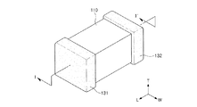
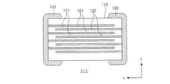
図3は、本発明の一実施形態による積層セラミックキャパシタを示す概略的な斜視図であり、図4は、図2のI−I'に沿って見た積層セラミックキャパシタを示す概略的な断面図である。
Multilayer Ceramic Capacitor FIG. 3 is a schematic perspective view showing a multilayer ceramic capacitor according to an embodiment of the present invention, and FIG. 4 is a schematic diagram showing a multilayer ceramic capacitor viewed along I-I'of FIG. It is a cross-sectional view.
図3及び図4を参照すると、本発明の他の実施例による積層セラミックキャパシタは、誘電体層111と、第1及び第2内部電極121、122が交互に積層されたセラミック本体110とを有する。セラミック本体110の両端部には、セラミック本体110の内部に交互に配置された第1及び第2内部電極121、122とそれぞれ導通する第1及び第2外部電極131、132が形成されている。
Referring to FIGS. 3 and 4, the multilayer ceramic capacitor according to another embodiment of the present invention has a
セラミック本体110の形状に特に制限はないが、一般的に六面体形状であることができる。また、その寸法にも特に制限はなく、用途によって適切な寸法にすることができ、例えば、(0.6〜5.6mm)×(0.3〜5.0mm)×(0.3〜1.9mm)であることができる。
The shape of the
誘電体層111の厚さは、キャパシタの容量設計に合わせて任意に変更することができるが、本発明の一実施例において、焼成後の誘電体層の厚さは、1層当たり、好ましくは0.2μm以上であることができる。薄過ぎる厚さの誘電体層は、一層内に存在する結晶粒数が小さく、信頼性に悪影響を及ぼすため、誘電体層の厚さは0.2μm以上であることができる。
The thickness of the
第1及び第2内部電極121、122は、各断面がセラミック本体110の対向する両端部の表面に交互に露出するように積層されている。第1及び第2外部電極131、132は、セラミック本体110の両端部に形成され、交互に配置された第1及び第2内部電極121、122の露出断面に電気的に連結してキャパシタ回路を構成する。
The first and second
第1及び第2内部電極121、122に含有される導電性材料は、特に限定されないが、本発明の一実施形態による誘電体組成物を使用してセラミック本体110を形成する場合、約1300℃以下の還元雰囲気で焼成が可能であると同時に、Ni成分を含む物質で内部電極121、122を形成することができる。
The conductive material contained in the first and second
第1及び第2内部電極121、122の厚さは、用途などによって適切に決められ、特に制限されるものではないが、例えば、0.1〜5μmまたは0.1〜2.5μmであることができる。
The thicknesses of the first and second
第1及び第2外部電極131、132に含有される導電性材料は、特に限定されないが、ニッケル(Ni)、銅(Cu)、またはこれらの合金を利用することができる。第1及び第2外部電極131、132の厚さは、用途などによって適切に決められ、特に制限されるものではないが、例えば、10〜50μmであることができる。
The conductive material contained in the first and second
セラミック本体110を構成する誘電体層111は、本発明の一実施形態による上述した組成の誘電体組成物を含むことができる。
The
上記誘電体組成物に対する具体的な説明は、上述した本発明の一実施形態による誘電体組成物の特徴と同一であり、ここでは省略する。 The specific description of the dielectric composition is the same as the characteristics of the dielectric composition according to the embodiment of the present invention described above, and is omitted here.
実験例
以下、本発明の発明者が行った実験例を通じて、本発明をさらに詳しく説明するが、これは、発明の具体的な理解を助けるためのもので、本発明の範囲が実験例のみによって限定されるものではない。
Experimental Examples The present invention will be described in more detail below through the experimental examples conducted by the inventor of the present invention, but this is for the purpose of assisting a concrete understanding of the invention, and the scope of the present invention is limited to the experimental examples. It is not limited.
母材のうち、第1主成分は、300nm級のBaTiO3粉末を使用し、第2主成分は、300nm級の(Ca,Sr)(Zr1−xTix)O3組成式(下記の表1では、「CSZT」と表示する)を有する粉末を使用した。そして、下記の表1のように、第1及び第2主成分の割合と、第2主成分のZrとTiとの割合を調整しながら、組成物のサンプルを製作した。 Of the base material, the first principal component uses 300 nm class BaTiO 3 powder, and the second principal component is a 300 nm class (Ca, Sr) (Zr 1-x Ti x ) O 3 composition formula (below). In Table 1, a powder having (denoted as "CSZT") was used. Then, as shown in Table 1 below, a sample of the composition was produced while adjusting the ratio of the first and second principal components and the ratio of the second principal components Zr and Ti.

サンプルの製作過程をより具体的に説明すると、スラリーの製作時は、母材主成分及び副成分パウダーをジルコニアボールを利用して混合/分散し、エタノール/トルエンと分散剤を混合した後、機械的ミーリングを実施した。以後、誘電体層が適切な水準の強度を有するようにバインダー混合工程を追加した。製造されたスラリーは、K2バルク試片の製作のために、小型ドクターブレード方式の成形塗布機(coater)を利用して10〜15μmの厚さで成形シートを製造し、圧着後、グリーン(green)試片の厚さが約0.8mmとなるように積層した後、1.0cm(横)×1.0cm(縦)サイズのK2バルク試片に切断した。 To explain the sample production process more specifically, when producing a slurry, the main component powder and auxiliary component powder of the base material are mixed / dispersed using zirconia balls, ethanol / toluene and a dispersant are mixed, and then the machine is used. Milling was carried out. After that, a binder mixing step was added so that the dielectric layer had an appropriate level of strength. The produced slurry is used to produce a molded sheet with a thickness of 10 to 15 μm using a small doctor blade type molding and coating machine (coater) for the production of K2 bulk specimen, and after crimping, it is green. ) After stacking the specimens so that the thickness of the specimens was about 0.8 mm, the specimens were cut into K2 bulk specimens having a size of 1.0 cm (horizontal) × 1.0 cm (vertical).
製作が完了したK2バルク試片は、400℃、エア(air)仮焼した後、焼成温度1300℃以下、水素濃度0.5%のH2以下の条件で焼成し、電気的特性及び絶縁抵抗、温度による容量変化率(TCC)等を測定した。バルクタイプK2で具現されたMLCCの常温静電容量及び誘電損失は、LCRメータを利用して1kHz、AC 1Vで測定し、10個ずつサンプルを取り、常温絶縁抵抗をDC電圧を印加した状態で、60秒経過後に測定した。温度による容量変化率(TCC)は、−55〜125℃の温度範囲で1kHz、AC 1Vの電圧印加条件で実施した。表1のように製作したサンプルに対して、誘電率、固有抵抗及び高温耐電圧テストを実行した結果は、下記の表2の通りである。ここで、各特性値と共に評価結果を表し、◎は優秀、○は良好、△は普通、Xは不良として処理されたものである。 K2 bulk specimen of manufacture is complete, 400 ° C., after air (air) calcining, sintering temperature 1300 ° C. or less, and calcined with H 2 under the following conditions hydrogen concentration of 0.5%, electrical properties and insulation resistance , Capacity change rate (TCC) with temperature was measured. The room temperature capacitance and dielectric loss of the MLCC embodied in the bulk type K2 are measured at 1 kHz and AC 1 V using an LCR meter, 10 samples are taken, and the room temperature insulation resistance is applied with a DC voltage. , Measured after 60 seconds. The rate of change in capacitance (TCC) with temperature was carried out in a temperature range of −55 to 125 ° C. under a voltage application condition of 1 kHz and AC 1 V. The results of the dielectric constant, intrinsic resistance, and high-temperature withstand voltage tests performed on the samples manufactured as shown in Table 1 are shown in Table 2 below. Here, the evaluation results are shown together with each characteristic value, where ⊚ is treated as excellent, ◯ is good, Δ is normal, and X is defective.
表1及び表2の実験結果をみると、まず、常誘電体材料である第2主成分の含量が増加するほど、組成物全体では誘電率が低下することを観察し、反対に、抵抗、耐電圧及び温度特性は、大幅に向上する傾向を示している。上記実験例に基づいて、上記異種物質の最適の混合割合を考慮すると、上記第1主成分のモル分率をa、上記第2主成分のモル分率をbとすると、0.33≦a/b≦3の条件を導出することができる。 Looking at the experimental results in Tables 1 and 2, it was first observed that the dielectric constant of the entire composition decreased as the content of the second principal component, which is a normal dielectric material, increased. Withstanding voltage and temperature characteristics tend to improve significantly. Considering the optimum mixing ratio of the dissimilar substances based on the above experimental example, assuming that the mole fraction of the first principal component is a and the mole fraction of the second principal component is b, 0.33 ≦ a. The condition of / b ≦ 3 can be derived.
また、ZrとTiの割合による特性変化をみると、Bサイト固溶元素であるTiが含まれた組成物の誘電率が相対的に高いことを確認することができた。具体的に、第2主成分(CSZT)でZr/Tiの割合を低くする場合、即ち、Tiの含量を相対的に高くする場合、強誘電体と常誘電体の混合システムで常誘電体、即ち、第2主成分の割合が増加することで発生し得る誘電特性の低下を緩和することができる。具体的に、相対的に低い誘電常数値を有する常誘電体物質の含量が増加しながら組成物全体の誘電率が低下する副効果があるが、Tiの含量増加によってこれを最小化することができる。このように誘電率の低下を最小化しながら、上述したように、常誘電体物質が有する安定的特性を通じて耐電圧と温度特性などを向上させることができる。上記実験例に基づいて、第2主成分のZrとTiの最適混合割合を考慮すると、上記第2主成分は組成式(Ca,Sr)(Zr1−xTix)O3で表され、xは、0.2≦x≦0.8の条件を導出することができる。 Moreover, when the characteristic change depending on the ratio of Zr and Ti was observed, it was confirmed that the dielectric constant of the composition containing Ti, which is a B-site solid solution element, was relatively high. Specifically, when the ratio of Zr / Ti is lowered in the second principal component (CSZT), that is, when the content of Ti is relatively high, the ferroelectric substance is used in a mixed system of ferroelectric and normal dielectric. That is, it is possible to alleviate the decrease in the dielectric property that may occur due to the increase in the proportion of the second main component. Specifically, there is a side effect that the dielectric constant of the entire composition decreases while the content of the dielectric substance having a relatively low dielectric constant value increases, but this can be minimized by increasing the content of Ti. it can. As described above, it is possible to improve the withstand voltage, the temperature characteristic, and the like through the stable characteristics of the normal dielectric material while minimizing the decrease in the dielectric constant in this way. Considering the optimum mixing ratio of Zr and Ti of the second principal component based on the above experimental example, the second principal component is represented by the composition formula (Ca, Sr) (Zr 1-x Ti x ) O 3 . For x, the condition of 0.2 ≦ x ≦ 0.8 can be derived.
以上、本発明の実施形態について詳細に説明したが、本発明の範囲はこれに限定されず、特許請求の範囲に記載された本発明の技術的思想から外れない範囲内で多様な修正及び変形が可能であるということは、当技術分野の通常の知識を有する者には明らかである。 Although the embodiments of the present invention have been described in detail above, the scope of the present invention is not limited to this, and various modifications and modifications are made without departing from the technical idea of the present invention described in the claims. It is clear to those with ordinary knowledge in the art that this is possible.
110 セラミック本体
111 誘電体層
121、122 第1及び第2内部電極
131、132 第1及び第2外部電極
110
Claims (14)
(Ca,Sr)(Zr,Ti)O3系列の常誘電体物質を第2主成分とし、
前記第1主成分のモル分率をa、前記第2主成分のモル分率をbとすると、0.33≦a/b≦1の条件を満たし、
前記第2主成分は、組成式(Ca,Sr)(Zr1−xTix)O3で表され、
ここで、xは、0.4≦x≦0.8の条件を満たす誘電体組成物。 (Ba, Ti) O 3 series ferroelectric substance as the first principal component,
(Ca, Sr) (Zr, Ti) O 3 series of normal dielectric material as the second main component
Assuming that the mole fraction of the first principal component is a and the mole fraction of the second principal component is b, the condition of 0.33 ≦ a / b ≦ 1 is satisfied.
The second main component is represented by the composition formula (Ca, Sr) (Zr 1-x Ti x ) O 3 .
Here, x is 0. 4 A dielectric composition satisfying the condition of ≤x≤0.8.
前記誘電体層は、
(Ba,Ti)O3系列の強誘電体物質を第1主成分、
(Ca,Sr)(Zr,Ti)O3系列の常誘電体物質を第2主成分とし、
前記第1主成分のモル分率をa、前記第2主成分のモル分率をbとすると、0.33≦a/b≦1の条件を満たし、
前記第2主成分は、組成式(Ca,Sr)(Zr1−xTix)O3で表され、
ここで、xは、0.4≦x≦0.8の条件を満たす誘電体組成物を含む積層セラミックキャパシタ。 Includes a ceramic body with alternating dielectric layers and internal electrodes
The dielectric layer is
(Ba, Ti) O 3 series ferroelectric substance as the first principal component,
(Ca, Sr) (Zr, Ti) O 3 series of normal dielectric material as the second main component
Assuming that the mole fraction of the first principal component is a and the mole fraction of the second principal component is b, the condition of 0.33 ≦ a / b ≦ 1 is satisfied.
The second main component is represented by the composition formula (Ca, Sr) (Zr 1-x Ti x ) O 3 .
Here, x is 0. 4 A multilayer ceramic capacitor containing a dielectric composition satisfying the condition of ≤x≤0.8.
Applications Claiming Priority (2)
| Application Number | Priority Date | Filing Date | Title |
|---|---|---|---|
| KR1020160001076A KR102516760B1 (en) | 2016-01-05 | 2016-01-05 | Dielectric composition and multilayer ceramic capacitor comprising the same |
| KR10-2016-0001076 | 2016-01-05 |
Publications (2)
| Publication Number | Publication Date |
|---|---|
| JP2017122037A JP2017122037A (en) | 2017-07-13 |
| JP6834092B2 true JP6834092B2 (en) | 2021-02-24 |
Family
ID=59305389
Family Applications (1)
| Application Number | Title | Priority Date | Filing Date |
|---|---|---|---|
| JP2016152257A Active JP6834092B2 (en) | 2016-01-05 | 2016-08-02 | Dielectric composition and multilayer ceramic capacitors containing it |
Country Status (2)
| Country | Link |
|---|---|
| JP (1) | JP6834092B2 (en) |
| KR (1) | KR102516760B1 (en) |
Families Citing this family (8)
| Publication number | Priority date | Publication date | Assignee | Title |
|---|---|---|---|---|
| KR102737558B1 (en) * | 2018-10-05 | 2024-12-03 | 삼성전기주식회사 | Method for manufacturing multi-layered ceramic electronic component and multi-layered ceramic electronic component |
| CN109516781A (en) * | 2018-11-29 | 2019-03-26 | 江苏大学 | A kind of quaternary system negative temperature coefficient thermistor material and preparation method thereof |
| CN109516780A (en) * | 2018-11-29 | 2019-03-26 | 镇江爱豪科思电子科技有限公司 | A kind of high-stability negative temperature coefficient heat-sensitive resistance material and preparation method thereof |
| KR20210138997A (en) | 2020-05-13 | 2021-11-22 | 삼성전자주식회사 | Capacitor, method of controlling the same, and transistor including the same |
| US11699552B2 (en) * | 2020-12-31 | 2023-07-11 | Samsung Electro-Mechanics Co., Ltd. | Multilayer ceramic electronic component |
| CN115985685B (en) * | 2022-12-06 | 2025-02-07 | 上海火炬电子科技集团有限公司 | A dielectric material for multilayer ceramic capacitor, capacitor and preparation method thereof |
| KR102812773B1 (en) * | 2022-12-19 | 2025-05-27 | 주식회사 아모텍 | Ceramic compostion having high temperature stability and ceramic capacitor including the same |
| CN117153564B (en) * | 2023-09-06 | 2024-10-15 | 潮州三环(集团)股份有限公司 | A composite electronic component and its preparation method and application |
Family Cites Families (7)
| Publication number | Priority date | Publication date | Assignee | Title |
|---|---|---|---|---|
| JPS60131708A (en) * | 1983-12-19 | 1985-07-13 | 株式会社村田製作所 | Nonreduced temperature compensating dielectric porcelain composition |
| JP3346293B2 (en) * | 1998-08-07 | 2002-11-18 | 株式会社村田製作所 | Non-reducing dielectric ceramic composition and multilayer ceramic capacitor using the same |
| JP2000281435A (en) | 1999-03-31 | 2000-10-10 | Tdk Corp | Dielectric composition and ceramic capacitor |
| JP4487371B2 (en) * | 1999-08-05 | 2010-06-23 | Tdk株式会社 | Dielectric composition and ceramic capacitor using the same |
| KR100444229B1 (en) | 2001-12-27 | 2004-08-16 | 삼성전기주식회사 | Nonreducible dielectric ceramic composition |
| JP5158113B2 (en) * | 2010-03-17 | 2013-03-06 | 株式会社村田製作所 | Dielectric ceramic composition and temperature compensation multilayer capacitor |
| KR101994709B1 (en) * | 2013-04-17 | 2019-07-01 | 삼성전기주식회사 | Dielectric composition, multilayer ceramic capacitor using the same, and method for preparing multilayer ceramic capacitor |
-
2016
- 2016-01-05 KR KR1020160001076A patent/KR102516760B1/en active Active
- 2016-08-02 JP JP2016152257A patent/JP6834092B2/en active Active
Also Published As
| Publication number | Publication date |
|---|---|
| KR20170081986A (en) | 2017-07-13 |
| JP2017122037A (en) | 2017-07-13 |
| KR102516760B1 (en) | 2023-03-31 |
Similar Documents
| Publication | Publication Date | Title |
|---|---|---|
| JP6834092B2 (en) | Dielectric composition and multilayer ceramic capacitors containing it | |
| JP6656882B2 (en) | Dielectric ceramic composition and multilayer ceramic capacitor including the same | |
| JP6834090B2 (en) | Dielectric composition and multilayer ceramic capacitors containing it | |
| JP5211262B1 (en) | Multilayer ceramic capacitor | |
| KR101883027B1 (en) | Dielectric ceramic composition, dielectric material and multilayer ceramic capacitor comprising the same | |
| JP6332648B2 (en) | Dielectric ceramic composition and multilayer ceramic capacitor including the same | |
| US20130162100A1 (en) | Dielectric composition and ceramic electronic component including the same | |
| JP6988039B2 (en) | Dielectric porcelain compositions, dielectric materials and multilayer ceramic capacitors containing them | |
| JP2017114759A (en) | Dielectric ceramic composition, dielectric material and multilayer ceramic capacitor including the same | |
| KR102097326B1 (en) | Dielectric ceramic composition and multilayer ceramic capacitor comprising the same | |
| CN110828167B (en) | Multilayer ceramic capacitor | |
| CN105916829B (en) | Dielectric combination, dielectric element, electronic unit and laminated electronic component | |
| JP6760689B2 (en) | Dielectric porcelain compositions, dielectric materials, and multilayer ceramic capacitors containing them | |
| US9255035B2 (en) | Dielectric ceramic composition and multilayer ceramic capacitor containing the same | |
| JP2016108231A (en) | Dielectric ceramic composition and multilayer ceramic capacitor containing the same | |
| JP6841479B2 (en) | Dielectric composition and multilayer ceramic capacitors containing it | |
| JP6870803B2 (en) | Dielectric porcelain composition and multilayer ceramic capacitors containing it | |
| JPWO2006006333A1 (en) | Dielectric ceramic composition and multilayer ceramic capacitor | |
| CN105622091B (en) | Dielectric ceramic composition and electronic device using the same | |
| JP7311256B2 (en) | Dielectric composition and electronic component using the same | |
| JP2007234677A (en) | Dielectric ceramic composition and laminated ceramic capacitor using same | |
| JP2014198660A (en) | Dielectric ceramic composition and multi-layer ceramic capacitor comprising the same | |
| JP7262640B2 (en) | ceramic capacitor | |
| JP4506233B2 (en) | Dielectric ceramic and multilayer ceramic capacitors | |
| WO2023080069A1 (en) | Dielectric ceramic composition and ceramic capacitor |
Legal Events
| Date | Code | Title | Description |
|---|---|---|---|
| A621 | Written request for application examination |
Free format text: JAPANESE INTERMEDIATE CODE: A621 Effective date: 20190705 |
|
| A977 | Report on retrieval |
Free format text: JAPANESE INTERMEDIATE CODE: A971007 Effective date: 20200717 |
|
| A131 | Notification of reasons for refusal |
Free format text: JAPANESE INTERMEDIATE CODE: A131 Effective date: 20200721 |
|
| A521 | Request for written amendment filed |
Free format text: JAPANESE INTERMEDIATE CODE: A523 Effective date: 20200929 |
|
| TRDD | Decision of grant or rejection written | ||
| A01 | Written decision to grant a patent or to grant a registration (utility model) |
Free format text: JAPANESE INTERMEDIATE CODE: A01 Effective date: 20210105 |
|
| A61 | First payment of annual fees (during grant procedure) |
Free format text: JAPANESE INTERMEDIATE CODE: A61 Effective date: 20210108 |
|
| R150 | Certificate of patent or registration of utility model |
Ref document number: 6834092 Country of ref document: JP Free format text: JAPANESE INTERMEDIATE CODE: R150 |
|
| R250 | Receipt of annual fees |
Free format text: JAPANESE INTERMEDIATE CODE: R250 |
|
| R250 | Receipt of annual fees |
Free format text: JAPANESE INTERMEDIATE CODE: R250 |
|
| R250 | Receipt of annual fees |
Free format text: JAPANESE INTERMEDIATE CODE: R250 |