JP7013860B2 - モータ駆動装置 - Google Patents
モータ駆動装置 Download PDFInfo
- Publication number
- JP7013860B2 JP7013860B2 JP2017252189A JP2017252189A JP7013860B2 JP 7013860 B2 JP7013860 B2 JP 7013860B2 JP 2017252189 A JP2017252189 A JP 2017252189A JP 2017252189 A JP2017252189 A JP 2017252189A JP 7013860 B2 JP7013860 B2 JP 7013860B2
- Authority
- JP
- Japan
- Prior art keywords
- rotation speed
- smoothing capacitor
- deterioration
- value
- motor
- Prior art date
- Legal status (The legal status is an assumption and is not a legal conclusion. Google has not performed a legal analysis and makes no representation as to the accuracy of the status listed.)
- Active
Links
Images




Classifications
-
- H—ELECTRICITY
- H02—GENERATION; CONVERSION OR DISTRIBUTION OF ELECTRIC POWER
- H02P—CONTROL OR REGULATION OF ELECTRIC MOTORS, ELECTRIC GENERATORS OR DYNAMO-ELECTRIC CONVERTERS; CONTROLLING TRANSFORMERS, REACTORS OR CHOKE COILS
- H02P27/00—Arrangements or methods for the control of AC motors characterised by the kind of supply voltage
- H02P27/04—Arrangements or methods for the control of AC motors characterised by the kind of supply voltage using variable-frequency supply voltage, e.g. inverter or converter supply voltage
- H02P27/06—Arrangements or methods for the control of AC motors characterised by the kind of supply voltage using variable-frequency supply voltage, e.g. inverter or converter supply voltage using DC to AC converters or inverters
-
- H—ELECTRICITY
- H02—GENERATION; CONVERSION OR DISTRIBUTION OF ELECTRIC POWER
- H02K—DYNAMO-ELECTRIC MACHINES
- H02K7/00—Arrangements for handling mechanical energy structurally associated with dynamo-electric machines, e.g. structural association with mechanical driving motors or auxiliary dynamo-electric machines
- H02K7/006—Structural association of a motor or generator with the drive train of a motor vehicle
-
- H—ELECTRICITY
- H02—GENERATION; CONVERSION OR DISTRIBUTION OF ELECTRIC POWER
- H02P—CONTROL OR REGULATION OF ELECTRIC MOTORS, ELECTRIC GENERATORS OR DYNAMO-ELECTRIC CONVERTERS; CONTROLLING TRANSFORMERS, REACTORS OR CHOKE COILS
- H02P31/00—Arrangements for regulating or controlling electric motors not provided for in groups H02P1/00 - H02P5/00, H02P7/00 or H02P21/00 - H02P29/00
-
- H—ELECTRICITY
- H02—GENERATION; CONVERSION OR DISTRIBUTION OF ELECTRIC POWER
- H02P—CONTROL OR REGULATION OF ELECTRIC MOTORS, ELECTRIC GENERATORS OR DYNAMO-ELECTRIC CONVERTERS; CONTROLLING TRANSFORMERS, REACTORS OR CHOKE COILS
- H02P6/00—Arrangements for controlling synchronous motors or other dynamo-electric motors using electronic commutation dependent on the rotor position; Electronic commutators therefor
- H02P6/28—Arrangements for controlling current
-
- H—ELECTRICITY
- H02—GENERATION; CONVERSION OR DISTRIBUTION OF ELECTRIC POWER
- H02M—APPARATUS FOR CONVERSION BETWEEN AC AND AC, BETWEEN AC AND DC, OR BETWEEN DC AND DC, AND FOR USE WITH MAINS OR SIMILAR POWER SUPPLY SYSTEMS; CONVERSION OF DC OR AC INPUT POWER INTO SURGE OUTPUT POWER; CONTROL OR REGULATION THEREOF
- H02M1/00—Details of apparatus for conversion
- H02M1/0003—Details of control, feedback or regulation circuits
- H02M1/0038—Circuits or arrangements for suppressing, e.g. by masking incorrect turn-on or turn-off signals, e.g. due to current spikes in current mode control
-
- H—ELECTRICITY
- H02—GENERATION; CONVERSION OR DISTRIBUTION OF ELECTRIC POWER
- H02M—APPARATUS FOR CONVERSION BETWEEN AC AND AC, BETWEEN AC AND DC, OR BETWEEN DC AND DC, AND FOR USE WITH MAINS OR SIMILAR POWER SUPPLY SYSTEMS; CONVERSION OF DC OR AC INPUT POWER INTO SURGE OUTPUT POWER; CONTROL OR REGULATION THEREOF
- H02M1/00—Details of apparatus for conversion
- H02M1/14—Arrangements for reducing ripples from DC input or output
-
- H—ELECTRICITY
- H02—GENERATION; CONVERSION OR DISTRIBUTION OF ELECTRIC POWER
- H02M—APPARATUS FOR CONVERSION BETWEEN AC AND AC, BETWEEN AC AND DC, OR BETWEEN DC AND DC, AND FOR USE WITH MAINS OR SIMILAR POWER SUPPLY SYSTEMS; CONVERSION OF DC OR AC INPUT POWER INTO SURGE OUTPUT POWER; CONTROL OR REGULATION THEREOF
- H02M7/00—Conversion of AC power input into DC power output; Conversion of DC power input into AC power output
- H02M7/42—Conversion of DC power input into AC power output without possibility of reversal
- H02M7/44—Conversion of DC power input into AC power output without possibility of reversal by static converters
- H02M7/48—Conversion of DC power input into AC power output without possibility of reversal by static converters using discharge tubes with control electrode or semiconductor devices with control electrode
- H02M7/53—Conversion of DC power input into AC power output without possibility of reversal by static converters using discharge tubes with control electrode or semiconductor devices with control electrode using devices of a triode or transistor type requiring continuous application of a control signal
- H02M7/537—Conversion of DC power input into AC power output without possibility of reversal by static converters using discharge tubes with control electrode or semiconductor devices with control electrode using devices of a triode or transistor type requiring continuous application of a control signal using semiconductor devices only, e.g. single switched pulse inverters
- H02M7/5387—Conversion of DC power input into AC power output without possibility of reversal by static converters using discharge tubes with control electrode or semiconductor devices with control electrode using devices of a triode or transistor type requiring continuous application of a control signal using semiconductor devices only, e.g. single switched pulse inverters in a bridge configuration
-
- H—ELECTRICITY
- H02—GENERATION; CONVERSION OR DISTRIBUTION OF ELECTRIC POWER
- H02P—CONTROL OR REGULATION OF ELECTRIC MOTORS, ELECTRIC GENERATORS OR DYNAMO-ELECTRIC CONVERTERS; CONTROLLING TRANSFORMERS, REACTORS OR CHOKE COILS
- H02P29/00—Arrangements for regulating or controlling electric motors, appropriate for both AC and DC motors
- H02P29/60—Controlling or determining the temperature of the motor or of the drive
Landscapes
- Engineering & Computer Science (AREA)
- Power Engineering (AREA)
- Inverter Devices (AREA)
Description
モータ(3)を駆動するインバータ(20)に接続された平滑コンデンサ(32)について、初期状態の静電容量に相関する値の初期値を記憶する記憶部(72)と、
初期値が格納された状態で、平滑コンデンサの静電容量に相関し、且つ、初期値に対応する値を計測する計測部(60,73)と、
計測部による計測値と初期値とに基づいて、平滑コンデンサに劣化が生じているか否かを判定する判定部(74)と、
劣化が生じていると判定された場合には、モータの最大回転数を制限する制限部(75)と、を備え、
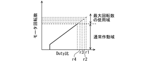
モータの回転域として、目標回転数とモータの実回転数とに基づいて閉ループ制御されたときに取り得る回転域である通常作動域と、開ループ制御され、通常作動域よりも高回転の領域である最大回転数の使用域と、を有し、
制限部は、使用域内において、最大回転数を制限する。
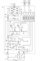
先ず、図1及び図2に基づき、本実施形態のモータ駆動装置について説明する。
(式1)α={(tps-tp)/tps}×100
本実施形態は、先行実施形態を参照できる。このため、先行実施形態に示したモータ駆動装置10と共通する部分についての説明は省略する。
40…電源リレー、41…抵抗、42…スイッチ、43…抵抗、50…プリチャージ回路、51,52,53…スイッチ、54,55…抵抗、56…ダイオード、60…タイミング生成回路、61,62…コンパレータ、63,64,65…抵抗、70…マイコン、71…制御部、72…記憶部、73…算出部、74…判定部、75…制限部、CMP1,CMP2…コンパレータ
Claims (4)
- モータ(3)を駆動するインバータ(20)に接続された平滑コンデンサ(32)について、初期状態の静電容量に相関する値の初期値を記憶する記憶部(72)と、
前記初期値が格納された状態で、前記平滑コンデンサの静電容量に相関し、且つ、前記初期値に対応する値を計測する計測部(60,73)と、
前記計測部による計測値と前記初期値とに基づいて、前記平滑コンデンサに劣化が生じているか否かを判定する判定部(74)と、
劣化が生じていると判定された場合には、前記モータの最大回転数を制限する制限部(75)と、を備え、
前記モータの回転域として、目標回転数と前記モータの実回転数とに基づいて閉ループ制御されたときに取り得る回転域である通常作動域と、開ループ制御され、前記通常作動域よりも高回転の領域である前記最大回転数の使用域と、を有し、
前記制限部は、前記使用域内において、前記最大回転数を制限するモータ駆動装置。 - 前記判定部は、劣化が生じている場合に劣化の度合いも判定し、
前記制限部は、前記判定部により判定された劣化の度合いに応じて、前記最大回転数を段階的に制限する請求項1に記載のモータ駆動装置。 - 前記平滑コンデンサは、電源リレー(40)をオンする前にプリチャージ回路(50)によって充電され、
前記初期値及び前記計測値は、プリチャージ中の前記平滑コンデンサの両端電圧に基づく値である請求項1または請求項2に記載のモータ駆動装置。 - 前記初期状態は、出荷状態である請求項1~3いずれか1項に記載のモータ駆動装置。
Priority Applications (2)
| Application Number | Priority Date | Filing Date | Title |
|---|---|---|---|
| JP2017252189A JP7013860B2 (ja) | 2017-12-27 | 2017-12-27 | モータ駆動装置 |
| US16/221,823 US10868487B2 (en) | 2017-12-27 | 2018-12-17 | Motor drive device configured to detect capacitor deterioration and to restrict a motor based upon the detected deterioration |
Applications Claiming Priority (1)
| Application Number | Priority Date | Filing Date | Title |
|---|---|---|---|
| JP2017252189A JP7013860B2 (ja) | 2017-12-27 | 2017-12-27 | モータ駆動装置 |
Publications (2)
| Publication Number | Publication Date |
|---|---|
| JP2019118236A JP2019118236A (ja) | 2019-07-18 |
| JP7013860B2 true JP7013860B2 (ja) | 2022-02-01 |
Family
ID=66949037
Family Applications (1)
| Application Number | Title | Priority Date | Filing Date |
|---|---|---|---|
| JP2017252189A Active JP7013860B2 (ja) | 2017-12-27 | 2017-12-27 | モータ駆動装置 |
Country Status (2)
| Country | Link |
|---|---|
| US (1) | US10868487B2 (ja) |
| JP (1) | JP7013860B2 (ja) |
Families Citing this family (3)
| Publication number | Priority date | Publication date | Assignee | Title |
|---|---|---|---|---|
| JP7336639B2 (ja) * | 2018-09-19 | 2023-09-01 | パナソニックIpマネジメント株式会社 | 突入電流抑制装置及びモータ駆動装置 |
| JP2022099977A (ja) * | 2020-12-23 | 2022-07-05 | 日本電産トーソク株式会社 | モータ制御装置および電動ポンプ装置 |
| CN117413453A (zh) * | 2021-10-05 | 2024-01-16 | 株式会社日立产机系统 | 电力转换装置和平滑电容器的劣化判断方法 |
Citations (1)
| Publication number | Priority date | Publication date | Assignee | Title |
|---|---|---|---|---|
| JP2010233425A (ja) | 2009-03-30 | 2010-10-14 | Fujitsu General Ltd | コンデンサの劣化検出回路及びこれを備えた電子機器 |
Family Cites Families (12)
| Publication number | Priority date | Publication date | Assignee | Title |
|---|---|---|---|---|
| JPH0322821A (ja) * | 1989-06-19 | 1991-01-31 | Daikin Ind Ltd | 電源用電解コンデンサの故障診断装置 |
| JPH0919003A (ja) * | 1995-06-27 | 1997-01-17 | Honda Motor Co Ltd | 電動車両におけるコンデンサの劣化判定装置 |
| JP4362962B2 (ja) | 2000-09-27 | 2009-11-11 | 富士電機システムズ株式会社 | コンデンサの良否判定装置 |
| JP2008164453A (ja) | 2006-12-28 | 2008-07-17 | Mitsubishi Electric Corp | インバータ装置の平滑コンデンサ寿命判定装置 |
| DE112008000590T5 (de) * | 2007-03-13 | 2010-04-15 | Komatsu Ltd. | Generatormotoransteuervorrichtung und Verfahren zum Entladen von Ladungen aus einer Kapazität der Generatormotoransteuervorrichtung |
| JP2008271779A (ja) | 2007-03-29 | 2008-11-06 | Sanyo Electric Co Ltd | 電気機器 |
| EP2352199B1 (en) * | 2008-11-21 | 2015-08-26 | Honda Motor Co., Ltd. | Charge control device |
| JP2011106987A (ja) | 2009-11-18 | 2011-06-02 | Panasonic Electric Works Co Ltd | 電源装置及びコンデンサ寿命判定方法 |
| JP2014193060A (ja) | 2013-03-28 | 2014-10-06 | Panasonic Corp | 電源装置 |
| JP6386315B2 (ja) | 2014-09-19 | 2018-09-05 | 日立オートモティブシステムズ株式会社 | モータ駆動装置 |
| JP6262686B2 (ja) * | 2015-04-27 | 2018-01-17 | ファナック株式会社 | 平滑コンデンサの寿命予測手段を有するモータ制御装置 |
| JP2018191370A (ja) | 2017-04-28 | 2018-11-29 | 株式会社デンソー | 電源装置 |
-
2017
- 2017-12-27 JP JP2017252189A patent/JP7013860B2/ja active Active
-
2018
- 2018-12-17 US US16/221,823 patent/US10868487B2/en active Active
Patent Citations (1)
| Publication number | Priority date | Publication date | Assignee | Title |
|---|---|---|---|---|
| JP2010233425A (ja) | 2009-03-30 | 2010-10-14 | Fujitsu General Ltd | コンデンサの劣化検出回路及びこれを備えた電子機器 |
Also Published As
| Publication number | Publication date |
|---|---|
| JP2019118236A (ja) | 2019-07-18 |
| US20190199264A1 (en) | 2019-06-27 |
| US10868487B2 (en) | 2020-12-15 |
Similar Documents
| Publication | Publication Date | Title |
|---|---|---|
| JP4807058B2 (ja) | 車両用電源装置 | |
| JP5835009B2 (ja) | 電源装置 | |
| KR101055340B1 (ko) | 스위칭 레귤레이터 및 그 동작 제어 방법 | |
| JP6205254B2 (ja) | 充電制御装置 | |
| US20100193266A1 (en) | Power Supply Apparatus And Electric Vehicle | |
| US8736209B2 (en) | Drive and control circuit for motor system and the method thereof | |
| JP6507040B2 (ja) | 充電器 | |
| JP4175258B2 (ja) | 圧縮機ユニットおよびそれを用いた冷凍機 | |
| JP7013860B2 (ja) | モータ駆動装置 | |
| JP5077030B2 (ja) | モータ駆動回路およびモータの異常判定方法 | |
| US9537433B2 (en) | Motor drive device | |
| JP2006127455A (ja) | 半導体素子制御装置 | |
| JP2019122158A (ja) | 突入電流抑制回路 | |
| JP5640956B2 (ja) | 電力変換装置 | |
| US10135234B2 (en) | Preventive apparatus | |
| CN110361669B (zh) | 电池劣化判定装置 | |
| JP2017123740A (ja) | スイッチング電源 | |
| US20190165561A1 (en) | Power supply control apparatus, power supply control method, and computer program | |
| JP2021061655A (ja) | 電源装置 | |
| JP4148243B2 (ja) | 異常検出回路 | |
| JP2017201863A (ja) | モータ駆動装置 | |
| JP5544741B2 (ja) | 制御装置 | |
| JP7059946B2 (ja) | 電源制御回路 | |
| JP2019049929A (ja) | 電力検出装置及び加熱装置 | |
| JP3931604B2 (ja) | 直流モータ速度制御装置 |
Legal Events
| Date | Code | Title | Description |
|---|---|---|---|
| A621 | Written request for application examination |
Free format text: JAPANESE INTERMEDIATE CODE: A621 Effective date: 20201117 |
|
| A977 | Report on retrieval |
Free format text: JAPANESE INTERMEDIATE CODE: A971007 Effective date: 20210916 |
|
| A131 | Notification of reasons for refusal |
Free format text: JAPANESE INTERMEDIATE CODE: A131 Effective date: 20211026 |
|
| A521 | Request for written amendment filed |
Free format text: JAPANESE INTERMEDIATE CODE: A523 Effective date: 20211207 |
|
| TRDD | Decision of grant or rejection written | ||
| A01 | Written decision to grant a patent or to grant a registration (utility model) |
Free format text: JAPANESE INTERMEDIATE CODE: A01 Effective date: 20211221 |
|
| A61 | First payment of annual fees (during grant procedure) |
Free format text: JAPANESE INTERMEDIATE CODE: A61 Effective date: 20220103 |
|
| R151 | Written notification of patent or utility model registration |
Ref document number: 7013860 Country of ref document: JP Free format text: JAPANESE INTERMEDIATE CODE: R151 |
|
| R250 | Receipt of annual fees |
Free format text: JAPANESE INTERMEDIATE CODE: R250 |
|
| R250 | Receipt of annual fees |
Free format text: JAPANESE INTERMEDIATE CODE: R250 |