JPWO2017191802A1 - 切れ刃の軌道を補正する方法、記録媒体およびプログラム - Google Patents
切れ刃の軌道を補正する方法、記録媒体およびプログラム Download PDFInfo
- Publication number
- JPWO2017191802A1 JPWO2017191802A1 JP2018515713A JP2018515713A JPWO2017191802A1 JP WO2017191802 A1 JPWO2017191802 A1 JP WO2017191802A1 JP 2018515713 A JP2018515713 A JP 2018515713A JP 2018515713 A JP2018515713 A JP 2018515713A JP WO2017191802 A1 JPWO2017191802 A1 JP WO2017191802A1
- Authority
- JP
- Japan
- Prior art keywords
- cutting edge
- rotationally symmetric
- cutting
- symmetric surface
- axis
- Prior art date
- Legal status (The legal status is an assumption and is not a legal conclusion. Google has not performed a legal analysis and makes no representation as to the accuracy of the status listed.)
- Granted
Links
Images




Classifications
-
- G—PHYSICS
- G05—CONTROLLING; REGULATING
- G05B—CONTROL OR REGULATING SYSTEMS IN GENERAL; FUNCTIONAL ELEMENTS OF SUCH SYSTEMS; MONITORING OR TESTING ARRANGEMENTS FOR SUCH SYSTEMS OR ELEMENTS
- G05B19/00—Program-control systems
- G05B19/02—Program-control systems electric
- G05B19/18—Numerical control [NC], i.e. automatically operating machines, in particular machine tools, e.g. in a manufacturing environment, so as to execute positioning, movement or co-ordinated operations by means of program data in numerical form
- G05B19/401—Numerical control [NC], i.e. automatically operating machines, in particular machine tools, e.g. in a manufacturing environment, so as to execute positioning, movement or co-ordinated operations by means of program data in numerical form characterised by control arrangements for measuring, e.g. calibration and initialisation, measuring workpiece for machining purposes
-
- B—PERFORMING OPERATIONS; TRANSPORTING
- B23—MACHINE TOOLS; METAL-WORKING NOT OTHERWISE PROVIDED FOR
- B23B—TURNING; BORING
- B23B1/00—Methods for turning or working essentially requiring the use of turning-machines; Use of auxiliary equipment in connection with such methods
-
- B—PERFORMING OPERATIONS; TRANSPORTING
- B23—MACHINE TOOLS; METAL-WORKING NOT OTHERWISE PROVIDED FOR
- B23Q—DETAILS, COMPONENTS, OR ACCESSORIES FOR MACHINE TOOLS, e.g. ARRANGEMENTS FOR COPYING OR CONTROLLING; MACHINE TOOLS IN GENERAL CHARACTERISED BY THE CONSTRUCTION OF PARTICULAR DETAILS OR COMPONENTS; COMBINATIONS OR ASSOCIATIONS OF METAL-WORKING MACHINES, NOT DIRECTED TO A PARTICULAR RESULT
- B23Q15/00—Automatic control or regulation of feed movement, cutting velocity or position of tool or work
- B23Q15/20—Automatic control or regulation of feed movement, cutting velocity or position of tool or work before or after the tool acts upon the workpiece
- B23Q15/22—Control or regulation of position of tool or workpiece
-
- B—PERFORMING OPERATIONS; TRANSPORTING
- B23—MACHINE TOOLS; METAL-WORKING NOT OTHERWISE PROVIDED FOR
- B23C—MILLING
- B23C3/00—Milling particular work; Special milling operations; Machines therefor
- B23C3/16—Working surfaces curved in two directions
-
- G—PHYSICS
- G05—CONTROLLING; REGULATING
- G05B—CONTROL OR REGULATING SYSTEMS IN GENERAL; FUNCTIONAL ELEMENTS OF SUCH SYSTEMS; MONITORING OR TESTING ARRANGEMENTS FOR SUCH SYSTEMS OR ELEMENTS
- G05B19/00—Program-control systems
- G05B19/02—Program-control systems electric
- G05B19/18—Numerical control [NC], i.e. automatically operating machines, in particular machine tools, e.g. in a manufacturing environment, so as to execute positioning, movement or co-ordinated operations by means of program data in numerical form
- G05B19/402—Numerical control [NC], i.e. automatically operating machines, in particular machine tools, e.g. in a manufacturing environment, so as to execute positioning, movement or co-ordinated operations by means of program data in numerical form characterised by control arrangements for positioning, e.g. centring a tool relative to a hole in the workpiece, additional detection means to correct position
-
- G—PHYSICS
- G05—CONTROLLING; REGULATING
- G05B—CONTROL OR REGULATING SYSTEMS IN GENERAL; FUNCTIONAL ELEMENTS OF SUCH SYSTEMS; MONITORING OR TESTING ARRANGEMENTS FOR SUCH SYSTEMS OR ELEMENTS
- G05B19/00—Program-control systems
- G05B19/02—Program-control systems electric
- G05B19/18—Numerical control [NC], i.e. automatically operating machines, in particular machine tools, e.g. in a manufacturing environment, so as to execute positioning, movement or co-ordinated operations by means of program data in numerical form
- G05B19/404—Numerical control [NC], i.e. automatically operating machines, in particular machine tools, e.g. in a manufacturing environment, so as to execute positioning, movement or co-ordinated operations by means of program data in numerical form characterised by control arrangements for compensation, e.g. for backlash, overshoot, tool offset, tool wear, temperature, machine construction errors, load, inertia
-
- B—PERFORMING OPERATIONS; TRANSPORTING
- B23—MACHINE TOOLS; METAL-WORKING NOT OTHERWISE PROVIDED FOR
- B23Q—DETAILS, COMPONENTS, OR ACCESSORIES FOR MACHINE TOOLS, e.g. ARRANGEMENTS FOR COPYING OR CONTROLLING; MACHINE TOOLS IN GENERAL CHARACTERISED BY THE CONSTRUCTION OF PARTICULAR DETAILS OR COMPONENTS; COMBINATIONS OR ASSOCIATIONS OF METAL-WORKING MACHINES, NOT DIRECTED TO A PARTICULAR RESULT
- B23Q15/00—Automatic control or regulation of feed movement, cutting velocity or position of tool or work
- B23Q15/20—Automatic control or regulation of feed movement, cutting velocity or position of tool or work before or after the tool acts upon the workpiece
- B23Q15/22—Control or regulation of position of tool or workpiece
- B23Q15/24—Control or regulation of position of tool or workpiece of linear position
-
- G—PHYSICS
- G05—CONTROLLING; REGULATING
- G05B—CONTROL OR REGULATING SYSTEMS IN GENERAL; FUNCTIONAL ELEMENTS OF SUCH SYSTEMS; MONITORING OR TESTING ARRANGEMENTS FOR SUCH SYSTEMS OR ELEMENTS
- G05B2219/00—Program-control systems
- G05B2219/30—Nc systems
- G05B2219/37—Measurements
- G05B2219/37506—Correction of position error
-
- G—PHYSICS
- G05—CONTROLLING; REGULATING
- G05B—CONTROL OR REGULATING SYSTEMS IN GENERAL; FUNCTIONAL ELEMENTS OF SUCH SYSTEMS; MONITORING OR TESTING ARRANGEMENTS FOR SUCH SYSTEMS OR ELEMENTS
- G05B2219/00—Program-control systems
- G05B2219/30—Nc systems
- G05B2219/37—Measurements
- G05B2219/37576—Post-process, measure worpiece after machining, use results for new or same
-
- G—PHYSICS
- G05—CONTROLLING; REGULATING
- G05B—CONTROL OR REGULATING SYSTEMS IN GENERAL; FUNCTIONAL ELEMENTS OF SUCH SYSTEMS; MONITORING OR TESTING ARRANGEMENTS FOR SUCH SYSTEMS OR ELEMENTS
- G05B2219/00—Program-control systems
- G05B2219/30—Nc systems
- G05B2219/49—Nc machine tool, till multiple
- G05B2219/49166—Compensation for measured deviation of tool path, as function of lenght of path
-
- G—PHYSICS
- G05—CONTROLLING; REGULATING
- G05B—CONTROL OR REGULATING SYSTEMS IN GENERAL; FUNCTIONAL ELEMENTS OF SUCH SYSTEMS; MONITORING OR TESTING ARRANGEMENTS FOR SUCH SYSTEMS OR ELEMENTS
- G05B2219/00—Program-control systems
- G05B2219/30—Nc systems
- G05B2219/49—Nc machine tool, till multiple
- G05B2219/49343—Machining point symmetrical surfaces, revolving surfaces
Landscapes
- Engineering & Computer Science (AREA)
- Mechanical Engineering (AREA)
- Human Computer Interaction (AREA)
- Manufacturing & Machinery (AREA)
- Physics & Mathematics (AREA)
- General Physics & Mathematics (AREA)
- Automation & Control Theory (AREA)
- Numerical Control (AREA)
- Automatic Control Of Machine Tools (AREA)
- Turning (AREA)
Abstract
Description
さまざまな要因によって、工作物の加工後の形状が、目標の形状に対してずれることが起こり得る。そのうちの1つの要因は、切れ刃の摩耗である。しかし切れ刃を交換するためには工作機械を停止しなければならない。生産性の観点からは、できるだけ長い時間、機械を連続的に稼働することが好ましい。
[本開示の効果]
本開示によれば、回転対称面の高い精度での切削加工を繰り返して実現することができる。
最初に本発明の実施態様を列記して説明する。
以下、図面に基づいて本発明の実施の形態を説明する。以下の図面において同一または相当する部分には同一の参照番号を付し、その説明は繰返さない。なお、説明を分かりやすくするために、図面において、発明の構成要素の一部のみが示される場合がある。
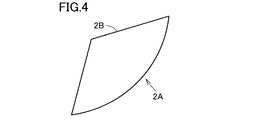
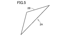
図4は、本発明の実施の形態に係る加工方法に使用される切れ刃の一例を示した模式図である。図5は、本発明の実施の形態に係る加工方法に使用される切れ刃の他の例を示した模式図である。
(1)切れ刃の全体の使用
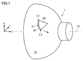
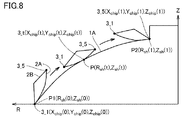
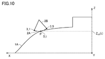
切れ刃2Aの軌道は、XYZ座標系によって表現される。X軸、Y軸およびZ軸の各々の方向は、図1に示されるように定義される。
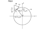
図9は、回転対称面1Aおよび切れ刃2AをXY平面上で表現したモデル図である。図9において、XY平面は、切削点Pを含む平面である。切れ刃2Aの先端3_1のX座標およびY座標は、(X(t),Y(t))と表される。切れ刃2Aの点3_tの位置は、先端3_1の位置に対して(Xchip(t),Ychip(t))だけ異なる。したがって、切れ刃2Aの点3_tのX座標およびY座標は、(X(t)+Xchip(t),Y(t)+Y chip(t))と表される。
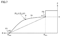
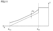
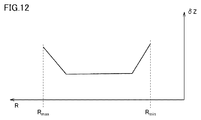
図11は、加工後の回転対称面1Aの形状と目標の形状との間のずれを示した模式図である。図11を参照して、δZは、加工後の回転対称面1Aの形状と目標の形状との間のZ軸方向の寸法のずれである。図12は、図11に示されたZ軸方向のずれδZと、半径Rとの関係の一例を示した図である。図12に示されるように、RmaxからRminまでの間のRの変化に応じて、δZが変化する。したがってδZは、Rの関数として表すことができる。半径Rは、tに応じて変化する。したがって、この関数をRsh(t)と表す。
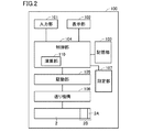
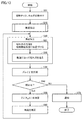
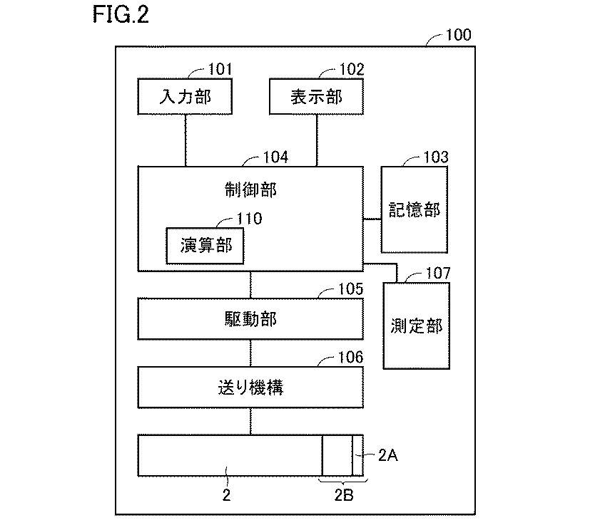
図13は、本発明の実施の形態に係る補正方法を含む、機械部品の製造方法を示したフローチャートである。以下に説明する処理は、記憶部103に記憶されたプログラムを制御部104が読み出すことによって実行される。図13に示されるように、ステップS01において、切削チップ2Bがホルダ2に取り付けられる。さらに、ホルダ2が製造装置100(送り機構106)に取り付けられる。
図14は、本発明の実施の形態に係る切削加工が適用される回転対称面の一例を示した図である。図14を参照して、回転対称面1Aは、円錐台の側面である。回転対称面1Aの半径Rは、Z軸方向に沿ってR=150[mm]からR=50[mm]まで直線的に変化する。
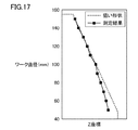
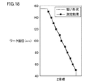
図15は、補正前の軌道に沿って直線状の切れ刃を移動させたときの切削形状を示す図である。図16は、補正後の軌道に沿って直線状の切れ刃を移動させたときの切削形状を示す図である。「狙い形状」とは、目標の形状を意味する。
Claims (5)
- 回転している工作物の回転対称面を切削加工する切れ刃の軌道を補正する方法であって、
前記切れ刃は、前記工作物の回転軸線に対して斜めに配置されて、前記回転対称面に接触しながら、前記回転軸線に対して傾斜した方向に移動し、
前記切れ刃の移動により、前記回転対称面に接する前記切れ刃の点は、前記切れ刃に沿って、前記切れ刃の第1の端部から、前記第1の端部の反対側にある前記切れ刃の第2の端部へと移動し、
前記補正する方法は、
測定部により、切削加工後の前記回転対称面の形状を測定するステップと、
前記回転対称面の目標の形状に対する、前記回転対称面の測定された形状の、前記回転軸線の方向の誤差を、演算部により算出するステップと、
前記演算部により、前記切れ刃の前記第1の端部の前記回転軸線の方向の成分を、前記誤差に基づいて補正するステップとを備える、切れ刃の軌道を補正する方法。 - 前記回転軸線をZ軸とし、前記回転対称面の回転半径の方向の軸をX軸とし、前記Z軸および前記X軸の両方に直交する軸をY軸とした三次元直交座標系において、
0から1まで変化する変数tにより、前記切れ刃の前記第1の端部の補正される前の軌道は(X(t),Y(t),Z(t))と表され、
前記回転半径をRshと表すと、
の関係が成立し、
前記算出するステップにおいて、前記演算部は、前記誤差を、Z軸方向の関数δZ(R sh(t))として求め、
前記補正するステップにおいて、前記演算部は、前記第1の端部の補正前の軌道を、(X(t),Y(t),Z(t)−δZ(Rsh(t)))へと補正する、請求項1に記載の切れ刃の軌道を補正する方法。 - 前記測定するステップにおいて、前記測定部により、前記回転対称面上の少なくとも3点において前記回転軸線の方向の誤差が測定され、
前記算出するステップにおいて、前記演算部は、前記誤差の測定結果から補間によって前記関数δZ(Rsh(t))を決定する、請求項2に記載の切れ刃の軌道を補正する方法。 - 切れ刃の軌道を補正する方法をコンピュータに実行させるプログラムを記録した、コンピュータ読み取り可能な記録媒体であって、
前記切れ刃は、回転している工作物の回転軸線に対して斜めに配置されて、前記工作物の回転対称面に接触しながら、前記回転軸線を横断するように移動し、
前記切れ刃の移動により、前記回転対称面に接する前記切れ刃の点は、前記切れ刃に沿って、前記切れ刃の第1の端部から、前記第1の端部の反対側にある前記切れ刃の第2の端部へと移動し、
記録媒体は、プログラムがコンピュータに、
測定部によって切削加工後の前記回転対称面の形状を測定した結果を受け付けるステップと、
前記回転対称面の目標の形状に対する、前記回転対称面の測定された形状の、前記回転軸線の方向の誤差を算出するステップと、
前記切れ刃の前記第1の端部の軌道の前記回転軸線の方向の成分を、前記誤差に基づいて補正するステップとを実行させる、コンピュータ読み取り可能な記録媒体。 - 切れ刃の軌道を補正する方法をコンピュータに実行させるプログラムであって、
前記切れ刃は、回転している工作物の回転軸線に対して斜めに配置されて、前記工作物の回転対称面に接触しながら、前記回転軸線を横断するように移動し、
前記切れ刃の移動により、前記回転対称面に接する前記切れ刃の点は、前記切れ刃に沿って、前記切れ刃の第1の端部から、前記第1の端部の反対側にある前記切れ刃の第2の端部へと移動し、
プログラムは、コンピュータに、
測定部によって切削加工後の前記回転対称面の形状を測定した結果を受け付けるステップと、
前記回転対称面の目標の形状に対する、前記回転対称面の測定された形状の、前記回転軸線の方向の誤差を算出するステップと、
前記切れ刃の第1の端部の軌道の前記回転軸線の方向の成分を、前記誤差に基づいて補正するステップとを実行させる、プログラム。
Applications Claiming Priority (3)
| Application Number | Priority Date | Filing Date | Title |
|---|---|---|---|
| JP2016092410 | 2016-05-02 | ||
| JP2016092410 | 2016-05-02 | ||
| PCT/JP2017/016721 WO2017191802A1 (ja) | 2016-05-02 | 2017-04-27 | 切れ刃の軌道を補正する方法、記録媒体およびプログラム |
Publications (2)
| Publication Number | Publication Date |
|---|---|
| JPWO2017191802A1 true JPWO2017191802A1 (ja) | 2019-03-14 |
| JP6838056B2 JP6838056B2 (ja) | 2021-03-03 |
Family
ID=60202994
Family Applications (1)
| Application Number | Title | Priority Date | Filing Date |
|---|---|---|---|
| JP2018515713A Active JP6838056B2 (ja) | 2016-05-02 | 2017-04-27 | 切れ刃の軌道を補正する方法、記録媒体およびプログラム |
Country Status (5)
| Country | Link |
|---|---|
| US (1) | US10906151B2 (ja) |
| EP (1) | EP3454145B1 (ja) |
| JP (1) | JP6838056B2 (ja) |
| CN (1) | CN109154805B (ja) |
| WO (1) | WO2017191802A1 (ja) |
Families Citing this family (2)
| Publication number | Priority date | Publication date | Assignee | Title |
|---|---|---|---|---|
| JP6734361B2 (ja) * | 2016-03-04 | 2020-08-05 | 住友電工ハードメタル株式会社 | 機械部品の製造方法、機械部品の製造装置、回転対称面の加工方法、記録媒体およびプログラム |
| JP7120512B2 (ja) * | 2019-11-22 | 2022-08-17 | Smc株式会社 | 軌跡制御装置 |
Family Cites Families (22)
| Publication number | Priority date | Publication date | Assignee | Title |
|---|---|---|---|---|
| US4513380A (en) * | 1982-09-07 | 1985-04-23 | General Electric Company | Method of tool recovery in threadcutting apparatus |
| WO1994009419A1 (fr) * | 1992-10-09 | 1994-04-28 | Fanuc Ltd | Appareil a commande numerique |
| JPH0780752A (ja) * | 1993-09-14 | 1995-03-28 | Nikon Corp | 数値制御方法および数値制御システム |
| JP2706420B2 (ja) * | 1993-12-27 | 1998-01-28 | 村田機械株式会社 | Nc工作機械の工具刃先位置補正方法及びその装置 |
| EP0792707A1 (en) * | 1996-02-21 | 1997-09-03 | Matsushita Electric Industrial Co., Ltd. | Chip-breaking turning method and apparatus |
| JP3038160B2 (ja) * | 1996-12-10 | 2000-05-08 | ファナック株式会社 | 旋盤におけるネジ切リ加工方法 |
| US5910199A (en) * | 1997-02-26 | 1999-06-08 | Vickers, Incorporated | Method and apparatus for fast threading pullout in a numerically controlled threading application |
| JP4346824B2 (ja) * | 1998-12-24 | 2009-10-21 | 三菱電機株式会社 | 数値制御装置 |
| EP1253988B1 (de) | 1999-12-17 | 2003-07-02 | BOEHRINGER WERKZEUGMASCHINEN GmbH | Verfahren zur drallfreien spanenden bearbeitung von rotationssymmetrischen flächen |
| JP2002011617A (ja) * | 2000-06-23 | 2002-01-15 | Yamazaki Mazak Corp | 工作機械 |
| JP2002154007A (ja) * | 2000-09-05 | 2002-05-28 | Yamazaki Mazak Corp | 複合工具 |
| DE10144649C5 (de) * | 2001-09-11 | 2008-11-13 | Boehringer Werkzeugmaschinen Gmbh | Verfahren zur drallfreien spanenden Bearbeitung von rotationssymmetrischen Flächen |
| US7089838B2 (en) * | 2004-01-28 | 2006-08-15 | Kennametal Inc. | Zero centerline toolholder assembly |
| JP2007118100A (ja) * | 2005-10-26 | 2007-05-17 | Olympus Corp | 回転軸対称曲面の加工方法、回転軸対称曲面加工装置 |
| WO2007112603A1 (de) * | 2006-04-03 | 2007-10-11 | Thyssenkrupp Presta Ag | Überwachungseinrichtung für die funktion einer elektronischen steuerungseinrichtung und verfahren hierzu |
| JP5189806B2 (ja) * | 2006-09-07 | 2013-04-24 | 株式会社ミツトヨ | 表面形状測定装置 |
| WO2008096847A1 (ja) * | 2007-02-09 | 2008-08-14 | Mori Seiki Co., Ltd. | 自動プログラミング方法及び自動プログラミング装置 |
| CN101620282B (zh) * | 2008-06-30 | 2011-11-30 | 鸿富锦精密工业(深圳)有限公司 | 非球面透镜模具加工方法 |
| CN102145471B (zh) * | 2010-02-10 | 2016-03-16 | 中村留精密工业株式会社 | 硬质脆性板的倒角装置 |
| CN202752730U (zh) * | 2012-08-05 | 2013-02-27 | 中国第一重型机械股份公司 | 法兰密封槽内表面环向全位置tig自动堆焊设备 |
| WO2015079836A1 (ja) * | 2013-11-29 | 2015-06-04 | 村田機械株式会社 | 工作機械及び切削方法 |
| WO2015129567A1 (ja) * | 2014-02-27 | 2015-09-03 | 村田機械株式会社 | 工作機械 |
-
2017
- 2017-04-27 JP JP2018515713A patent/JP6838056B2/ja active Active
- 2017-04-27 CN CN201780027715.8A patent/CN109154805B/zh active Active
- 2017-04-27 EP EP17792735.7A patent/EP3454145B1/en active Active
- 2017-04-27 WO PCT/JP2017/016721 patent/WO2017191802A1/ja not_active Ceased
- 2017-04-27 US US16/098,204 patent/US10906151B2/en active Active
Also Published As
| Publication number | Publication date |
|---|---|
| CN109154805B (zh) | 2021-07-23 |
| EP3454145B1 (en) | 2025-10-29 |
| CN109154805A (zh) | 2019-01-04 |
| US10906151B2 (en) | 2021-02-02 |
| EP3454145A4 (en) | 2020-05-13 |
| US20190152010A1 (en) | 2019-05-23 |
| JP6838056B2 (ja) | 2021-03-03 |
| WO2017191802A1 (ja) | 2017-11-09 |
| EP3454145A1 (en) | 2019-03-13 |
Similar Documents
| Publication | Publication Date | Title |
|---|---|---|
| US20240393762A1 (en) | Method for processing workpiece and machine for processing workpiece | |
| KR20210073567A (ko) | 워크의 가공 방법 및 워크의 가공기 | |
| US10960471B2 (en) | Method for manufacturing machine component, apparatus for manufacturing machine component, method for machining rotation symmetry plane, recording medium, and program | |
| JP6734361B2 (ja) | 機械部品の製造方法、機械部品の製造装置、回転対称面の加工方法、記録媒体およびプログラム | |
| JP6679599B2 (ja) | 機械部品の製造方法、機械部品の製造装置、回転対称面の加工方法、記録媒体およびプログラム | |
| JPWO2017191802A1 (ja) | 切れ刃の軌道を補正する方法、記録媒体およびプログラム | |
| JP2017121688A (ja) | スパイラルベベルギヤまたはハイポイドギヤの製造方法 | |
| JP2020069622A (ja) | 歯車加工シミュレーション装置及び加工用工具 | |
| JP6720543B2 (ja) | 歯車加工方法 | |
| JP6175082B2 (ja) | 機械部品の製造方法、機械部品の製造装置、回転対称面の加工方法、記録媒体およびプログラム | |
| JP6175096B2 (ja) | 機械部品の製造方法、機械部品の製造装置、回転対称面の加工方法、記録媒体およびプログラム |
Legal Events
| Date | Code | Title | Description |
|---|---|---|---|
| A521 | Request for written amendment filed |
Free format text: JAPANESE INTERMEDIATE CODE: A821 Effective date: 20181030 |
|
| A621 | Written request for application examination |
Free format text: JAPANESE INTERMEDIATE CODE: A621 Effective date: 20191223 |
|
| A131 | Notification of reasons for refusal |
Free format text: JAPANESE INTERMEDIATE CODE: A131 Effective date: 20200714 |
|
| TRDD | Decision of grant or rejection written | ||
| A01 | Written decision to grant a patent or to grant a registration (utility model) |
Free format text: JAPANESE INTERMEDIATE CODE: A01 Effective date: 20210119 |
|
| A61 | First payment of annual fees (during grant procedure) |
Free format text: JAPANESE INTERMEDIATE CODE: A61 Effective date: 20210210 |
|
| R150 | Certificate of patent or registration of utility model |
Ref document number: 6838056 Country of ref document: JP Free format text: JAPANESE INTERMEDIATE CODE: R150 |
|
| R250 | Receipt of annual fees |
Free format text: JAPANESE INTERMEDIATE CODE: R250 |
|
| R250 | Receipt of annual fees |
Free format text: JAPANESE INTERMEDIATE CODE: R250 |
|
| R250 | Receipt of annual fees |
Free format text: JAPANESE INTERMEDIATE CODE: R250 |