KR20090056830A - Connection system for the crane boom segment - Google Patents
Connection system for the crane boom segment Download PDFInfo
- Publication number
- KR20090056830A KR20090056830A KR1020080114465A KR20080114465A KR20090056830A KR 20090056830 A KR20090056830 A KR 20090056830A KR 1020080114465 A KR1020080114465 A KR 1020080114465A KR 20080114465 A KR20080114465 A KR 20080114465A KR 20090056830 A KR20090056830 A KR 20090056830A
- Authority
- KR
- South Korea
- Prior art keywords
- boom
- connector
- connectors
- extensions
- segment
- Prior art date
- Legal status (The legal status is an assumption and is not a legal conclusion. Google has not performed a legal analysis and makes no representation as to the accuracy of the status listed.)
- Withdrawn
Links
- 230000013011 mating Effects 0.000 claims abstract description 5
- 238000000034 method Methods 0.000 claims description 15
- 230000007935 neutral effect Effects 0.000 description 9
- 230000006835 compression Effects 0.000 description 5
- 238000007906 compression Methods 0.000 description 5
- 238000003780 insertion Methods 0.000 description 4
- 230000037431 insertion Effects 0.000 description 4
- 238000004519 manufacturing process Methods 0.000 description 3
- 238000005266 casting Methods 0.000 description 2
- 238000003754 machining Methods 0.000 description 2
- 229910000831 Steel Inorganic materials 0.000 description 1
- 238000005452 bending Methods 0.000 description 1
- 230000002452 interceptive effect Effects 0.000 description 1
- 238000005304 joining Methods 0.000 description 1
- 239000010959 steel Substances 0.000 description 1
- 238000003466 welding Methods 0.000 description 1
Images


Classifications
-
- B—PERFORMING OPERATIONS; TRANSPORTING
- B66—HOISTING; LIFTING; HAULING
- B66C—CRANES; LOAD-ENGAGING ELEMENTS OR DEVICES FOR CRANES, CAPSTANS, WINCHES, OR TACKLES
- B66C23/00—Cranes comprising essentially a beam, boom, or triangular structure acting as a cantilever and mounted for translatory of swinging movements in vertical or horizontal planes or a combination of such movements, e.g. jib-cranes, derricks, tower cranes
- B66C23/62—Constructional features or details
- B66C23/64—Jibs
- B66C23/70—Jibs constructed of sections adapted to be assembled to form jibs or various lengths
-
- B—PERFORMING OPERATIONS; TRANSPORTING
- B66—HOISTING; LIFTING; HAULING
- B66C—CRANES; LOAD-ENGAGING ELEMENTS OR DEVICES FOR CRANES, CAPSTANS, WINCHES, OR TACKLES
- B66C23/00—Cranes comprising essentially a beam, boom, or triangular structure acting as a cantilever and mounted for translatory of swinging movements in vertical or horizontal planes or a combination of such movements, e.g. jib-cranes, derricks, tower cranes
-
- Y—GENERAL TAGGING OF NEW TECHNOLOGICAL DEVELOPMENTS; GENERAL TAGGING OF CROSS-SECTIONAL TECHNOLOGIES SPANNING OVER SEVERAL SECTIONS OF THE IPC; TECHNICAL SUBJECTS COVERED BY FORMER USPC CROSS-REFERENCE ART COLLECTIONS [XRACs] AND DIGESTS
- Y10—TECHNICAL SUBJECTS COVERED BY FORMER USPC
- Y10T—TECHNICAL SUBJECTS COVERED BY FORMER US CLASSIFICATION
- Y10T29/00—Metal working
- Y10T29/49—Method of mechanical manufacture
- Y10T29/49764—Method of mechanical manufacture with testing or indicating
- Y10T29/49778—Method of mechanical manufacture with testing or indicating with aligning, guiding, or instruction
- Y10T29/4978—Assisting assembly or disassembly
-
- Y—GENERAL TAGGING OF NEW TECHNOLOGICAL DEVELOPMENTS; GENERAL TAGGING OF CROSS-SECTIONAL TECHNOLOGIES SPANNING OVER SEVERAL SECTIONS OF THE IPC; TECHNICAL SUBJECTS COVERED BY FORMER USPC CROSS-REFERENCE ART COLLECTIONS [XRACs] AND DIGESTS
- Y10—TECHNICAL SUBJECTS COVERED BY FORMER USPC
- Y10T—TECHNICAL SUBJECTS COVERED BY FORMER US CLASSIFICATION
- Y10T29/00—Metal working
- Y10T29/49—Method of mechanical manufacture
- Y10T29/49826—Assembling or joining
- Y10T29/49947—Assembling or joining by applying separate fastener
-
- Y—GENERAL TAGGING OF NEW TECHNOLOGICAL DEVELOPMENTS; GENERAL TAGGING OF CROSS-SECTIONAL TECHNOLOGIES SPANNING OVER SEVERAL SECTIONS OF THE IPC; TECHNICAL SUBJECTS COVERED BY FORMER USPC CROSS-REFERENCE ART COLLECTIONS [XRACs] AND DIGESTS
- Y10—TECHNICAL SUBJECTS COVERED BY FORMER USPC
- Y10T—TECHNICAL SUBJECTS COVERED BY FORMER US CLASSIFICATION
- Y10T403/00—Joints and connections
- Y10T403/55—Member ends joined by inserted section
- Y10T403/553—Laterally inserted section
-
- Y—GENERAL TAGGING OF NEW TECHNOLOGICAL DEVELOPMENTS; GENERAL TAGGING OF CROSS-SECTIONAL TECHNOLOGIES SPANNING OVER SEVERAL SECTIONS OF THE IPC; TECHNICAL SUBJECTS COVERED BY FORMER USPC CROSS-REFERENCE ART COLLECTIONS [XRACs] AND DIGESTS
- Y10—TECHNICAL SUBJECTS COVERED BY FORMER USPC
- Y10T—TECHNICAL SUBJECTS COVERED BY FORMER US CLASSIFICATION
- Y10T403/00—Joints and connections
- Y10T403/70—Interfitted members
- Y10T403/7075—Interfitted members including discrete retainer
Landscapes
- Engineering & Computer Science (AREA)
- Mechanical Engineering (AREA)
- Jib Cranes (AREA)
Abstract
크레인은 붐 세그먼트 연결 시스템을 가진 붐을 포함한다. 붐은 적어도 제 1 붐 세그먼트와 제 2 붐 세그먼트를 포함하며, 이들 각각은 종축 및 제 1 단부와 제 2 단부를 가지고, 제 1 세그먼트의 제 2 단부는 제 2 세그먼트의 제 1 단부에 결합되며, 제 1 세그먼트의 제 2 단부 상의 하나 이상의 제 1 커넥터는 각각 제 2 세그먼트의 제 1 단부 상의 하나 이상의 제 2 커넥터와 짝을 이룬다. 제 1 커넥터와 제 2 커넥터는 각각 개구를 가진 하나 이상의 연장부를 포함한다. 이 개구들은 연장부들 내에 위치되고 종축에 수직인 축을 가지며 이에 따라 붐 세그먼트들이 나란하게 정렬될 때 제 1 커넥터와 제 2 커넥터와 짝을 이루는 모든 개구들이 나란하게 정렬된다. 본 발명의 한 특징에서, 제 1 커넥터는 제 1 정렬 표면을 포함하고 제 2 커넥터는 제 1 정렬 표면과 연결되는 제 2 정렬 표면을 포함하며, 제 1 정렬 표면과 제 2 정렬 표면이 완전히 연결될 때 붐 세그먼트들이 축방향으로 정렬되지 않는다 하더라도 메인 핀은 짝을 이룬 제 1 커넥터와 제 2 커넥터에서 모든 연장부들의 개구들을 통해 삽입될 수 있도록 커넥터들에서 연장부들을 통과하는 개구들은 나란하게 정렬된다. 본 발명의 또 다른 특징에서, 커넥터들은 스톱 표면들을 포함하며, 메인 핀이 붐 세그먼트들의 몇몇 코드들 상의 커넥터들의 연장부에서 개구를 통해 삽입될 수 있도록 동일한 붐 세그먼트들이 위치될 때, 스톱 표면들이 서로 접촉할 때 스톱 표면들이 그 외의 다른 커넥터들의 연장부에서 개구들을 나란하게 정렬하기 위해 협력하도록 커넥터들 상의 스톱 표면이 배치된다.
크레인 붐 세그먼트, 연장부, 스톱 표면, 정렬 표면, 붐 단면 부재, 압축 하중 지지 표면
The crane includes a boom with a boom segment connection system. The boom comprises at least a first boom segment and a second boom segment, each of which has a longitudinal axis and a first end and a second end, the second end of the first segment being coupled to the first end of the second segment, One or more first connectors on the second end of the first segment each mate with one or more second connectors on the first end of the second segment. The first connector and the second connector each comprise one or more extensions with openings. These openings are located in the extensions and have an axis perpendicular to the longitudinal axis so that when the boom segments are aligned side by side all the openings mating with the first connector and the second connector are aligned side by side. In one feature of the invention, the first connector comprises a first alignment surface and the second connector comprises a second alignment surface in connection with the first alignment surface, when the first alignment surface and the second alignment surface are fully connected. Even though the boom segments are not axially aligned, the openings through the extensions in the connectors are aligned side by side so that the main pin can be inserted through the openings of all the extensions in the mating first and second connectors. In another feature of the invention, the connectors comprise stop surfaces and when the same boom segments are positioned such that the main pin can be inserted through an opening in an extension of the connectors on some cords of the boom segments, the stop surfaces are mutually The stop surface on the connectors is arranged so that when in contact the stop surfaces cooperate to align the openings side by side in the extension of the other connectors.
Crane boom segment, extension, stop surface, alignment surface, boom section member, compressive load supporting surface
Description
본 발명은 리프트 크레인에 관한 것이며, 보다 구체적으로는 크레인들과 그와 유사한 것들을 위한 붐 단면 부재들을 나란하게 정렬하기 위한 연결 시스템에 관한 것이다.The present invention relates to a lift crane, and more particularly to a connection system for aligning boom cross-section members side by side for cranes and the like.
대용량 리프트 크레인은 통상 단부와 단부가 접촉하는 방식으로 고정된 붐 단면 부재들로 구성된 연신된 하중 지지 붐 구조물들을 포함한다. 각각의 붐 단면 부재들은 주로 복수의 코드(chord)들과 레이싱(lacing) 또는 격자 요소들로 제조된다. 각각의 단부 부분들의 말단은 일반적으로 붐 세그먼트들을 함께 접하도록 고정시키고 접하는 코드들 간의 압축 하중들을 수용하기 위하여 하나 또는 그 외의 다른 형태의 커넥터들이 제공된다. 통상적인 커넥터들은 2중 전단 압축 하중들을 수용하는 핀에 의해 고정된 수의 그리고 암의 러그(male and female lug)들을 포함한다.Large capacity lift cranes typically include elongated load-bearing boom structures consisting of boom cross-section members that are secured in end to end contact manner. Each boom cross section member is mainly made of a plurality of chords and lacing or grating elements. The distal end of each end portion is generally provided with one or other types of connectors to secure the boom segments abut together and to accommodate the compressive loads between the abutting cords. Typical connectors include a fixed number of male and female lugs by a pin that accepts double shear compression loads.
실례로서, 220피트의 붐은 크레인의 상부 구조물에 피벗회전 가능하도록 장착된 40피트의 붐 버트(boom butt), 하중을 들어 올리고 지탱하기 위한 리깅(rigging)과 쉬브(sheave)들로 구비된 30피트의 붐 탑(boom top), 이들 사이에 5개의 붐 단면 부재(1개는 길이 10피트, 1개는 길이 20피트 그리고 3개는 길이 40피트의 붐 단면 부재)들로 구성될 수 있다. 상기 붐은 6개의 붐 세그먼트 연결부들을 가진다. 통상 각각의 세그먼트는 4개의 코드, 4개의 연결부들을 가지며 이에 따라 붐을 조립하도록 핀 고정되고 나란하게 정렬되어야 하는 총 24개의 커넥터들로 구성된다.As an example, a 220 foot boom is a 40 foot boom butt mounted pivotally to a crane's upper structure, 30 with rigging and sheaves for lifting and supporting loads. It may consist of a boom top of the pit, five boom cross-section members (one 10 feet long, one 20 feet long and three 40 feet long boom cross-section members) between them. The boom has six boom segment connections. Each segment typically has four cords, four connections and thus consists of a total of 24 connectors that must be pinned and aligned side by side to assemble the boom.
대용량 크레인은 매우 큰 붐 횡단면들을 필요로 한다. 그 결과로, 심지어 붐 세그먼트들이 지면상에 평평하게 배열될 때에도 최상측 코드들 간의 핀 커넥터들은 일반적으로 지면으로부터 통상 8피트 또는 그 보다 높이 떨어져 있다. 리깅 작동자는 각각의 핀 위치로 사다리를 이동시키거나 또는 최상측 커넥터에 도달하기 위해 붐의 최상측에 서야 되고 그리고 붐의 최상측을 따라 이동해야 한다.Large capacity cranes require very large boom cross sections. As a result, the pin connectors between the uppermost cords are typically 8 feet or higher away from the ground, even when the boom segments are arranged flat on the ground. The rigging operator must stand on the top of the boom and move along the top of the boom to move the ladder to each pin position or to reach the top connector.
40피트 길이의 붐 단면 부재는 무게가 5,000lbs를 초과할 수 있다. 따라서 붐 부재를 들어올리기 위해서 보조 크레인이 요구된다. 첫 번째 리거(rigger)가 매달려 있는 붐 세그먼트를 고정시켜 나란하게 정렬하는 동안 두 번째 리거는 일반적으로 기다란 테이퍼를 가진 핀을 각각의 위치로 수동 작동시키기 위해 대형 해머(10 또는 15lbs)를 사용한다. 붐 세그먼트들을 연결하는 핀(pin)들은 일반적으로 코드들 간의 압축 하중들을 수용하도록 사용된다. 그 결과, 상기 핀들은 억지 끼워맞춤(tight fit)되고 게다가 붐을 조립하는 데 어려움이 증가된다. 이에 따라 예를 들어 220피트의 붐을 조립하는 데 3명(1명의 크레인 작동자와 2명의 리거)이 4시간 또는 그 이상 동안 작업을 해야 할 수도 있다. 크레인이 종종 이동되어야 할 경우, 붐을 조립하고 해체하는 데 소요되는 비용은 크레인이 사용되어야 하기 위한 하중을 들어 올리고 배치시키는 데 필요한 비용을 초과할 수 있다.A 40 foot long boom cross section member may weigh more than 5,000 lbs. Therefore, an auxiliary crane is required to lift the boom member. The second rigger typically uses a large hammer (10 or 15 lbs) to manually operate a pin with an elongated taper in each position while the first rigger holds the suspended boom segment in alignment. Pins connecting the boom segments are generally used to accommodate the compressive loads between the cords. As a result, the pins are tight fit and further increase the difficulty of assembling the boom. This may require, for example, three people (one crane operator and two riggers) to work for four hours or more to assemble a 220 foot boom. If the crane is often to be moved, the cost of assembling and disassembling the boom may exceed the cost of lifting and placing the load for the crane to be used.
대용량 크레인의 매우 큰 하중들을 수용하기 위하여, 2중 전단 연결(double shear connection)을 제공하는, 통상 2개의 암의 러그들 사이에 끼어져 있는 단일의 수의 러그는 압축 하중들을 수용하기 위해 매우 큰 핀 직경을 필요로 하고 이에 따라 커넥터들이 매우 커야 될 필요가 있다. 3개의 암의 러그들과 2개의 수의 러그들을 가진 공지된 커넥터들이 제공되지만, 섹션들이 조립될 때 붐 섹션들 사이의 자체-정렬되거나 또는 회전가능한 연결부(여기서 축방향으로 정렬되지 않고 그에 따라 연결부의 잔여부분이 형성될 수 있는 위치로 스윙회전될 때 초기에 붐 세그먼트들은 연결될 수 있음)를 제공하기 위한 타입의 붐 연결부들은 제공되지 않는다.In order to accommodate very large loads of high capacity cranes, a single number of lugs, usually sandwiched between the lugs of two arms, which provide a double shear connection, are very large to accommodate the compression loads. It requires a pin diameter and therefore the connectors need to be very large. Known connectors are provided with three female lugs and two numbers of lugs, but self-aligned or rotatable connections between the boom sections when the sections are assembled (where they are not axially aligned and thus the connections) Boom connections of the type for providing initially the boom segments can be connected when swinging to the position where the remainder of the can be formed are not provided.
따라서 붐 세그먼트들이 축방향으로 정렬되어 있지 않은 위치로부터 초기에 연결할 수 있고 붐 세그먼트들을 상대적으로 빠르게 연결할 수 있는, 용이하고 빠른 붐 세그먼트용 연결 시스템으로 인해 우수하게 개선될 것이다.It will therefore be a good improvement due to the easy and fast connection system for the boom segment, which can be initially connected from a position where the boom segments are not axially aligned and can connect the boom segments relatively quickly.
40피트 길이의 붐 단면 부재는 무게가 5,000lbs를 초과할 수 있다. 따라서 붐 부재를 들어올리기 위해서 보조 크레인이 요구된다. 첫 번째 리거(rigger)가 매달려 있는 붐 세그먼트를 고정시켜 나란하게 정렬하는 동안 두 번째 리거는 일반적으로 기다란 테이퍼를 가진 핀을 각각의 위치로 수동 작동시키기 위해 대형 해머(10 또는 15lbs)를 사용한다. 붐 세그먼트들을 연결하는 핀(pin)들은 일반적으로 코드들 간의 압축 하중들을 수용하도록 사용된다. 그 결과, 상기 핀들은 억지 끼워맞춤(tight fit)되고 게다가 붐을 조립하는 데 어려움이 증가된다. 이에 따라 예를 들어 220피트의 붐을 조립하는 데 3명(1명의 크레인 작동자와 2명의 리거)이 4시간 또는 그 이상 동안 작업을 해야 할 수도 있다. 크레인이 종종 이동되어야 할 경우, 붐을 조립하고 해체하는 데 소요되는 비용은 크레인이 사용되어야 하기 위한 하중을 들어 올리고 배치시키는 데 필요한 비용을 초과할 수 있다.A 40 foot long boom cross section member may weigh more than 5,000 lbs. Therefore, an auxiliary crane is required to lift the boom member. The second rigger typically uses a large hammer (10 or 15 lbs) to manually operate a pin with an elongated taper in each position while the first rigger holds the suspended boom segment in alignment. Pins connecting the boom segments are generally used to accommodate the compressive loads between the cords. As a result, the pins are tight fit and further increase the difficulty of assembling the boom. This may require, for example, three people (one crane operator and two riggers) to work for four hours or more to assemble a 220 foot boom. If the crane is often to be moved, the cost of assembling and disassembling the boom may exceed the cost of lifting and placing the load for the crane to be used.
대용량 크레인의 매우 큰 하중들을 수용하기 위하여, 2중 전단 연결(double shear connection)을 제공하는, 통상 2개의 암의 러그들 사이에 끼어져 있는 단일의 수의 러그는 압축 하중들을 수용하기 위해 매우 큰 핀 직경을 필요로 하고 이에 따라 커넥터들이 매우 커야할 필요가 있다. 3개의 암의 러그들과 2개의 수의 러그들을 가진 공지된 커넥터들이 제공되지만, 섹션들이 조립될 때 붐 섹션들 사이의 자체-정렬되거나 또는 회전가능한 연결부(여기서 축방향으로 정렬되지 않고 그에 따라 연결부의 잔여부분이 형성될 수 있는 위치로 스윙회전될 때 초기에 붐 세그먼 트들은 연결될 수 있음)를 제공하기 위한 타입의 붐 연결부들은 제공되지 않는다.In order to accommodate very large loads of high capacity cranes, a single number of lugs, usually sandwiched between the lugs of two arms, which provide a double shear connection, are very large to accommodate the compression loads. It requires a pin diameter and therefore the connectors need to be very large. Known connectors are provided with three female lugs and two numbers of lugs, but self-aligned or rotatable connections between the boom sections when the sections are assembled (where they are not axially aligned and thus the connections) Boom connections of the type for providing the boom segments can initially be connected when swinging to a position where the remainder of the can be formed are not provided.
개선된 붐 세그먼트용 연결 시스템이 발명되었다. 본 발명에 의하면, 붐 세그먼트들은 정렬 표면들 및/또는 스톱 표면들을 포함하는 커넥터들을 가지며, 이 정렬 표면들과 스톱 표면들로 인해 커넥터들은 핀을 삽입시키기 위해 용이하게 나란히 정렬될 수 있고 붐 세그먼트들은 초기에 연결될 수 있으며 그 뒤 세그먼트들 간의 연결부의 잔여부분들이 형성될 수 있도록 하는 최종 위치 내로 회전될 수 있다.An improved connection system for the boom segment has been invented. According to the invention, the boom segments have connectors comprising alignment surfaces and / or stop surfaces, which allow the connectors to be easily aligned side by side for inserting the pins and the boom segments It can be initially connected and then rotated into its final position allowing the remaining portions of the connections between the segments to be formed.
제 1 특징에서, 본 발명에 따른 크레인은 붐 세그먼트 연결 시스템을 포함하는 붐을 가지며, 상기 크레인은 하부 구조물들 상에 회전가능하게 장착된 상부 구조물들을 가지고, 상부 구조물들은 하중 호이스트 윈치를 포함하고,In a first aspect, the crane according to the invention has a boom comprising a boom segment connection system, the crane having upper structures rotatably mounted on the lower structures, the upper structures comprising a load hoist winch,
-붐은 종축 및 제 1 단부와 제 2 단부를 각각 가진 적어도 제 1 붐 세그먼트와 제 2 붐 세그먼트를 포함하며, 제 1 세그먼트의 제 2 단부는 제 2 세그먼트의 제 1 단부에 결합되고,The boom comprises at least a first boom segment and a second boom segment having a longitudinal axis and a first end and a second end, respectively, the second end of the first segment being coupled to the first end of the second segment,
-붐은 제 2 세그먼트의 제 1 단부 상의 하나 이상의 제 2 커넥터와 짝을 이룬 제 1 세그먼트의 제 2 단부 상의 하나 이상의 제 1 커넥터를 포함하며,The boom comprises at least one first connector on a second end of the first segment mated with at least one second connector on the first end of the second segment,
-제 1 커넥터와 제 2 커넥터는 이들을 통과하는 개구를 가진 하나 이상의 연장부(extension)를 각각 포함하며, 개구는 연장부들 내에 위치되고 종축에 수직인 축을 가지며 이에 따라 붐 세그먼트들이 나란하게 정렬될 때 제 1 커넥터와 제 2 커넥터와 짝을 이루는 모든 개구들이 나란하게 정렬되며,The first connector and the second connector each comprise one or more extensions with openings therethrough, the openings being located in the extensions and having an axis perpendicular to the longitudinal axis and thus the boom segments are aligned side by side. All openings mating with the first connector and the second connector are aligned side by side,
-하나 이상의 제 1 커넥터는 제 1 정렬 표면(first alignment surface)을 포함하고 하나 이상의 제 2 커넥터는 제 2 정렬 표면을 포함하며,At least one first connector comprises a first alignment surface and at least one second connector comprises a second alignment surface,
-제 1 정렬 표면과 제 2 정렬 표면은 협력하여 제 1 커넥터와 제 2 커넥터가 붐 조립 동안 함께 이동될 때 정렬 표면들로 인해 개구들이 연장부들을 통해 커넥터들에서 충분하게 정렬되도록 하는 상대적 위치 내로 붐 세그먼트들이 삽입되며 이에 따라 붐 세그먼트들이 축방향으로 정렬되지 않는다 하더라도 테이퍼 가공된 메인 핀(main pin)은 짝을 이룬 제 1 커넥터와 제 2 커넥터에서 연장부들의 개구들을 통해 삽입될 수 있다.The first alignment surface and the second alignment surface cooperate in a relative position such that when the first and second connectors are moved together during boom assembly, the alignment surfaces allow the openings to be sufficiently aligned in the connectors through the extensions. Even though the boom segments are inserted so that the boom segments are not axially aligned, the tapered main pin can be inserted through the openings of the extensions in the paired first and second connectors.
제 2 특징에서, 본 발명에 따른 크레인 붐 세그먼트(crane boom segment)에 있어서,In a second aspect, in the crane boom segment according to the invention,
-크레인 붐 세그먼트는 3개 이상의 코드들을 포함하며, 인터레이싱 요소(interlacing element)들은 고정되고 평행하게 코드들과 연결되어 붐 세그먼트를 형성하고, 3개 이상의 코드들의 하나 이상의 코드는 붐 세그먼트의 제 1 종방향 부분 내에 배열되며 3개 이상의 코드들의 잔여부분은 붐 세그먼트의 제 2 종방향 부분 내에 배열되고,The crane boom segment comprises three or more cords, wherein the interlacing elements are fixed and parallel to the cords to form a boom segment, wherein one or more cords of the three or more cords are the first of the boom segment Arranged in the longitudinal portion and the remainder of the three or more cords arranged in the second longitudinal portion of the boom segment,
-크레인 붐 세그먼트는 각각의 코드들의 제 1 단부와 제 2 단부 상에서 각각 커넥터를 포함하며, 커넥터들의 절반(half)은 제 1 유형(first type)으로 구성되고 연장부들을 가지며, 커넥터들의 절반은 제 2 유형(second type)으로 구성되고 연장부들을 가지며, 각각의 커넥터들은 스톱 표면을 포함하고,The crane boom segment comprises connectors on the first and second ends of the respective cords, the half of the connectors being of a first type and having extensions, and half of the connectors Composed of a second type and has extensions, each connector comprising a stop surface,
-연장부들은 메인 핀을 수용하도록 크기가 결정된 개구를 가지며, 연장부들과 개구들은 각각의 커넥터들 상에 배치되며 이에 따라 붐 세그먼트의 제 2 단부가 동일한 붐 세그먼트의 제 1 단부에 결합되고 그리고 상기 제 1 단부와 나란한 위치에 있으며 커넥터들은 2개의 붐 세그먼트 상에서 서로 결합될 때, 결합된 커넥터들의 연장부들은 서로 중첩되며 메인 핀들이 붐 세그먼트의 제 2 단부의 커넥터를 동일한 붐 세그먼트의 제 1 단부의 커넥터에 고정시키기 위해 개구들을 통해 삽입할 수 있도록 개구들이 정렬되며,The extensions have an opening sized to receive the main pin, the extensions and the openings being arranged on the respective connectors such that the second end of the boom segment is coupled to the first end of the same boom segment and said When the connectors are in parallel with the first end and the connectors are joined to each other on two boom segments, the extensions of the joined connectors overlap one another and the main pins connect the connector of the second end of the boom segment to the first end of the same boom segment. The openings are aligned so that they can be inserted through the openings to secure them to the connector,
-메인 핀이 붐 세그먼트들의 제 2 종방향 부분 상의 코드들의 잔여부분의 커넥터들의 연장부에서 개구를 통해 삽입될 수 있도록 동일한 붐 세그먼트가 위치될 때, 스톱 표면들이 서로 접촉할 때 스톱 표면들이 각각의 커넥터들의 연장부에서 개구들을 나란하게 정렬하기 위해 협력하도록 커넥터들 상의 스톱 표면이 배치된다.When the same boom segments are positioned so that the main pin can be inserted through the opening in the extension of the connectors of the remainder of the cords on the second longitudinal part of the boom segments, the stop surfaces are each in contact with each other. A stop surface on the connectors is arranged to cooperate to align the openings side by side in the extensions of the connectors.
또 다른 특징에서, 본 발명에 따른 2개의 붐 단면 부재들 간의 짝을 이룬 연결부(mated connection)에 있어서,In another feature, in a mated connection between two boom cross-section members according to the invention,
-상기 짝을 이룬 연결부는 제 1 붐 단면 부재의 단부에 부착된 제 1 커넥터와 제 2 붐 단면 부재의 단부에 부착된 제 2 커넥터를 포함하며,The mated connection comprises a first connector attached to an end of the first boom cross-section member and a second connector attached to an end of the second boom cross-section member,
-제 1 커넥터와 제 2 커넥터는 각각 제 1 세트의 연장부와 제 2 세트의 연장부를 가지고, 각각의 연장부는 핀을 수용하도록 크기가 결정된 개구를 가지며,The first connector and the second connector each have a first set of extensions and a second set of extensions, each extension having an opening sized to receive a pin,
-각각의 커넥터는 제 1 세트의 연장부와 제 2 세트의 연장부 사이에 위치된 압축 하중 지지 표면을 포함하고, 제 1 커넥터의 압축 하중 지지 표면은 제 2 커넥 터의 압축 하중 지지 표면과 면-대-면 관계(face-to-face relationship)에 있으며,Each connector comprises a compressive load bearing surface positioned between the first set of extensions and the second set of extensions, the compressive load bearing surface of the first connector being flush with the compressive load bearing surface of the second connector; In a face-to-face relationship,
-상기 짝을 이룬 연결부는 제 2 커넥터의 제 1 세트의 연장부와 제 1 커넥터의 제 1 세트의 연장부의 개구들을 통과하는 제 1 핀 및 제 2 커넥터의 제 2 세트의 연장부와 제 1 커넥터의 제 2 세트의 연장부의 개구들을 통과하는 제 2 핀을 포함한다.The mated connection is a first pin and a second set of extensions of the second connector and a first connector passing through openings of the first set of extensions of the first connector and the first set of extensions of the first connector A second pin through the openings of the second set of extensions of the second set.
또 다른 특징에서, 본 발명에 따른 2개의 붐 단면 부재들 간의 짝을 이룬 연결부에 있어서,In another feature, in a paired connection between two boom cross-section members according to the invention,
상기 짝을 이룬 연결부는The paired connection
-제 1 붐 단면 부재의 단부에 부착된 제 1 커넥터를 포함하며, 커넥터는 각각 개구를 가진 복수의 연장부들을 포함하고, 상기 짝을 이룬 연결부는 연장부들을 통과하는 부가적인 개구 내에 포획된 가이드 핀을 포함하며,A first connector attached to an end of the first boom cross-section member, the connector comprising a plurality of extensions each having an opening, the mated connection being guided in an additional opening through the extensions Pins,
-제 2 붐 단면 부재의 단부에 부착된 제 2 커넥터를 포함하며, 제 2 커넥터는 각각 개구를 가진 복수의 연장부들을 가지고, 제 1 커넥터의 연장부들은 제 2 커넥터의 연장부들과 포개지며(interleaved), 제 2 커넥터는 연장부들의 외측 상에 형성된 스톱 표면을 추가적으로 포함하고,A second connector attached to an end of the second boom cross-section member, the second connector each having a plurality of extensions with openings, the extensions of the first connector overlapping the extensions of the second connector ( interleaved), the second connector further comprises a stop surface formed on the outside of the extensions,
-제 1 커넥터와 제 2 커넥터를 피벗회전 하도록 고정하는 포개진 연장부들의 개구들을 통과하는 메인 핀을 포함하며, 스톱 표면과 가이드 핀은 붐 세그먼트들이 축방향으로 나란하게 정렬될 때 서로 접촉한다.A main pin passing through the openings of the nested extensions securing the first connector and the second connector to pivot, the stop surface and the guide pin contact each other when the boom segments are aligned side by side in the axial direction.
또 다른 특징에서, 본 발명에 따른 리프트 크레인 붐(lift crane boom)의 제 1 세그먼트와 제 2 세그먼트를 연결하는 방법으로서, 붐 세그먼트들은 각각 종축과 4개의 코드들을 포함하며, 각각의 코드들은 상기 코드들의 각각의 단부 상에서 커넥터를 가진 리프트 크레인 붐의 제 1 세그먼트와 제 2 세그먼트를 연결하는 방법에 있어서,In another aspect, a method of connecting a first segment and a second segment of a lift crane boom according to the invention, wherein the boom segments each comprise a longitudinal axis and four cords, each of the cords A method of connecting a first segment and a second segment of a lift crane boom with a connector on each end of the
상기 제 1 세그먼트와 제 2 세그먼트를 연결하는 방법은The method of connecting the first segment and the second segment
-제 1 붐 세그먼트 상의 2개의 커넥터들 상의 제 1 정렬 표면이 제 2 붐 세그먼트 상의 각각의 2개의 커넥터들 상의 제 2 정렬 표면과 접촉하여 2쌍의 연결된 커넥터들을 형성하지만, 2개의 세그먼트들의 종축들은 나란하게 정렬되지 않고 각 세그먼트 상의 남아있는 커넥터들은 결합되지 않도록 2개의 붐 세그먼트가 함께 이동하는 단계를 포함하며, 제 1 정렬 표면과 제 2 정렬 표면은 커넥터들에서 개구들을 나란하게 정렬하도록 협력하고,The first alignment surface on the two connectors on the first boom segment contacts the second alignment surface on each of the two connectors on the second boom segment to form two pairs of connected connectors, but the longitudinal axes of the two segments Remaining connectors on each segment that are not aligned side by side include moving two boom segments together so that the first and second alignment surfaces cooperate to align the openings in the connectors side by side,
-각각의 연결된 커넥터들을 핀과 함께 체결하여 피벗 회전하는 연결부를 제공하는 단계를 포함하며,-Engaging each connected connector with a pin to provide a pivotally rotating connection,
-제 1 세그먼트의 결합되지 않은 커넥터(non-coupled connector)들 상의 스톱 표면이 제 2 세그먼트의 결합되지 않은 커넥터들 상의 스톱 표면과 접촉할 때까지, 2개의 세그먼트들이 서로 피벗 회전하는 연결부 주위로 피벗 회전하는 단계를 포함하고,The two segments pivot around a connection in which the two segments pivot on each other until the stop surface on the non-coupled connectors of the first segment contacts the stop surface on the non-coupled connectors of the second segment. Rotating,
-결합되지 않은 커넥터들을 각각의 짝을 이룬 커넥터에 핀 고정하는 단계를 포함한다.Pinning the unjoined connectors to each mated connector.
붐 세그먼트들이 축방향으로 정렬되어 있지 않은 위치로부터 초기에 연결할 수 있고 붐 세그먼트들을 상대적으로 빠르게 연결할 수 있는, 용이하고 빠른 붐 세그먼트용 연결 시스템으로 인해 우수하게 개선될 것이다.It would be a good improvement due to the easy and fast connection system for the boom segment, which can be initially connected from a position where the boom segments are not axially aligned and which can connect the boom segments relatively quickly.
본 발명의 선호적인 실시예에 있어서, 리프트 크레인 붐의 큰 섹션들은 상대적으로 빠른 셋-업 시간(set-up time)으로 조립될 수 있는데 이는 정렬 표면들이 접촉하고 커넥터들이 각각의 위치로 이동될 때 핀들이 통과하는 개구들이 나란하게 정렬되기 때문이다. 게다가, 세그먼트들이 정렬되지 않은 위치로부터 연결될 필요가 있고, 한 세트의 핀이 제자리에 위치되고 나면, 섹션들은 개구들 내로 피벗회전 할 수 있고 개구들이 남아있는 커넥터들 상에서 이미 나란하게 정렬된 형상에서 자동적으로 중지할 것이다. 본 발명의 선호적인 실시예에 있어서, 최상측 핀 또는 바닥 핀들이 우선적으로 배치되건 간에 상기 사항이 적용될 것이다.In a preferred embodiment of the invention, the large sections of the lift crane boom can be assembled with a relatively fast set-up time when the alignment surfaces are in contact and the connectors are moved to their respective positions. The openings through which the pins pass are aligned side by side. In addition, the segments need to be connected from an unaligned position, and once a set of pins are in place, the sections can pivot in the openings and automatically in a shape already aligned side by side on the connectors where the openings remain. Will stop. In a preferred embodiment of the present invention, the above will apply whether the top or bottom pins are preferentially placed.
위에서 언급한 본 발명의 이점들과 그 외의 다른 이점들은 본 발명과 함께 하기 도면들과 그들에 대한 간단한 설명을 참조함으로써 더 잘 이해될 것이다.The above and other advantages of the present invention mentioned above will be better understood by reference to the following figures and brief description thereof in conjunction with the present invention.
본 발명은 이제 추가적으로 기술될 것이다. 하기에서, 본 발명의 서로 다른 특징들이 보다 상세하게 기술된다. 이렇게 기술된 각각의 특징은 명확히 상반되게 언급되지 않는 한 그 외의 다른 특징 또는 특징들과 조합될 수 있다. 특히, 선호적이거나 또는 바람직한 것으로 간주되는 하나의 특징은 선호적이거나 또는 바람직한 것으로 간주되는 그 외의 다른 특징 혹은 특징들과 조합될 수 있다.The present invention will now be further described. In the following, different features of the invention are described in more detail. Each feature so described may be combined with any other feature or features unless clearly stated to the contrary. In particular, one feature that is preferred or considered desirable may be combined with any other feature or features that are considered preferred or desirable.
참고로, 용어 "최상측(top)", "바닥(bottom)", "수평(horizontal)"과 "수직(vertical)"은, 일반적으로, 지면 위에서 또는 지면 근처에서 조립될 수 있는 위치에서 붐(boom)의 특정 부분들을 언급하기 위하여 본원과 청구항들에서 사용된다. 붐이, 수직 위치를 포함하여, 상이한 각도들로 들어 올려질 수 있음에도 불구하고 이 용어들이 여전히 적용된다.For reference, the terms "top", "bottom", "horizontal" and "vertical" are generally used in a position where the boom can be assembled on or near the ground. It is used herein and in the claims to refer to specific parts of (boom). Although the boom can be lifted at different angles, including the vertical position, these terms still apply.
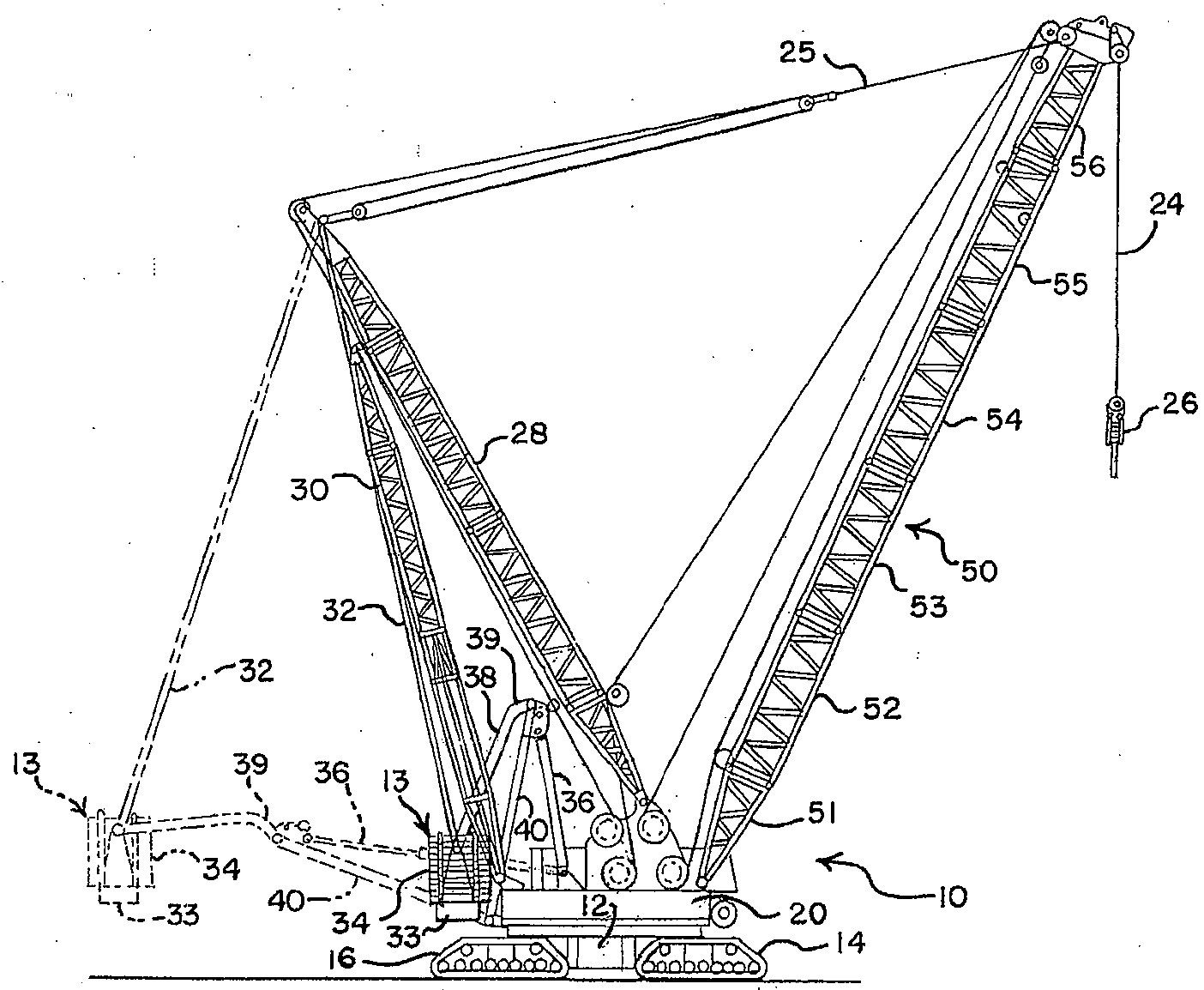
도 1에 도시된 바와 같이, 이동식 리프트 크레인(mobile lift crane, 10)은 카바디(carbody, 12)로서 언급되는 하부 구조물(lower work)들과 크롤러(crawler, 14, 16) 형태의 이동식 지면 연결 부재(ground engaging member)들을 포함한다. (물론 2개의 전방 크롤러(14)와 2개의 후방 크롤러(16)가 있지만 도 1의 측면도에서는 이들 중 오직 하나만이 도시된다.) 크레인(10)에서, 지면 연결 부재들은 한 면에 한 크롤러가 있는 단지 한 세트의 크롤러들로 구성될 수 있다. 물론, 도시된 크롤러 말고도 추가적인 크롤러 또는 타이어와 같은 그 외의 다른 지면 연결 부재들이 사용될 수 있다.As shown in FIG. 1, a
회전 베드(rotating bed, 20)는 롤러 패스(roller path)를 이용하여 카바디(12)에 회전가능하게 연결되며 이에 따라 상기 회전 베드(20)는 지면 연결 부재(14, 16)들에 대한 축 주위로 스윙운동 할 수 있다. 회전 베드는 상기 회전 베드의 전방 부분 상에 피벗회전 가능하게 장착된 붐(boom, 50), 회전 베드 상에서 상기 회전 베드의 제 1 단부에 장착된 마스트(mast, 28), 회전 베드의 후방 부분과 마스트 사이에 연결된 백히치(backhitch, 30) 및 지지 부재(support member, 33) 상에 평형추(counterweight, 34)를 가진 이동식 평형추 유닛(13)을 지탱한다. 평형 추들은 지지 부재(33) 상에서 다층(multiple stack) 형태의 독립적인 평형추 부재들로 구성될 수 있다.The rotating
붐(50)과 마스트(28)의 최상측 사이의 붐 호이스트 리깅(boom hoist rigging, 25)은 하중을 전달하고 붐 각도를 제어하도록 사용되며 이에 따라 평형추는 크레인에 의해 들어 올려진 하중의 균형을 맞추도록 사용될 수 있다. 호이스트 라인(hoist line, 24)은 붐(50)으로부터 연장되며 후크(hook, 26)를 지탱한다. 회전 베드(20)는 또한, 이동식 리프트 크레인 상에 일반적으로 존재하는, 호이스트 라인(24)과 리깅(25)용 호이스트 드럼(hoist drum)과 운전석과 같은 그 외의 다른 요소들도 포함한다. 필요시에, 붐(50)은 메인 붐의 최상측에 피벗 회전가능하게 장착된 루핑 지브(luffing jib) 또는 그 외의 다른 붐 형상들을 포함할 수 있다. 백히치(30)는 마스트(28)의 최상측에 인접하게 연결된다. 백히치(30)는 도 1에 도시된 바와 같이 인장 하중과 압축 하중 모두를 수용하도록 설계된 격자 부재(lattice member)를 포함할 수 있다. 크레인(10)에서, 마스트는 들어올리기 작동(pick), 이동 작동(move) 및 세트 작동(set)과 같은 크레인의 작동 동안 고정 각도로 회전 베드에 고정된다.Boom hoist rigging 25 between the
평형추 유닛은 회전 베드(20)의 나머지 부분(rest)에 대해 이동가능하다. 기술된 크레인 실시예에서, 평형추 유닛(13)은 크레인의 전방부에 대해서 안으로 그리고 밖으로 이동할 수 있도록 설계된다. 마스트의 최상측에 인접하게 연결된 인장 부재(32)는 평형추 유닛을 지탱한다. 평형추 운동 구조물(counterweight movement structure)은 회전 베드와 평형추 유닛 사이에 연결되며 이에 따라 평형추 유닛은 도 1에서 실선들로 도시된 바와 같이 마스트 최상측의 전방의 제 1 위치에 고정되고 상기 제 1 위치로 이동될 수 있으며, 도 1에서 점선들로 도시된 바와 같이 마스트 최상측의 후방의 제 2 위치에 고정되고 상기 제 2 위치로 이동될 수 있다.The counterweight unit is movable relative to the rest of the
크레인(10)에서, 유압식 실린더(36), 피벗 프레임(40) 및 후방 암(38)은 평형추 유닛을 이동시키도록 사용될 수 있다. (크롤러와 같이, 후방 암(38)은 실질적으로 좌측 부재와 우측 부재를 모두 가지며, 이들 중 오직 하나만이 도 1에 도시되고, 피벗 프레임은 2개의 측면 부재들을 가지며, 유압식 실린더는 직렬로 이동하는 2개의 실린더를 포함한다. 대안으로, 선호적으로 4개의 유압식 모터들로 전력이 공급되는 상대적으로 큰 유압식 실린더 또는 랙과 피니언 구조물은 선형 구동을 제공하기 위한 2개의 유압식 실린더(36) 대신에 사용될 수 있다. 게다가, 피벗 프레임은 견고한 판 구조물로 제조될 수 있으며 2개의 후방 암(38)들은 하나의 단일 구조물로 대체할 수 있다.) 피벗 프레임(40)은 회전 베드(20)와 유압식 실린더(26) 사이에 연결되며 후방 암(38)은 피벗 프레임(40)과 평형추 유닛 사이에 연결된다. 유압식 실린더(36)는 상기 유압식 실린더(36)를 한 지점으로 상승시키는 서포트 프레임(support frame) 상에서 회전 베드(20)에 피벗 회전가능하게 연결되며 이에 따라 실린더(36), 피벗 프레임(40) 및 후방 암(38)의 기하학적인 배열로서 전체 운동 범위를 통해 평형추가 이동될 수 있다. 이런 방식으로 실린더(36)로 인해 후방 암(38)은 실린더가 수축되고 확장될 때 평형추 유닛을 이동시킬 수 있다.In the
암(38)들은 피벗 프레임(40)에 연결된 단부에서 각진 부분(angled portion, 39)을 가진다. 이로 인해 암(38)들은 피벗 프레임(40)의 측면 부재들과 일직선으로 직접 연결될 수 있다. 상기 각진 부분(39)으로 인해 평형추가 도 1에서 실선들로 도시된 부분에 있을 때 암(38)들이 피벗 프레임의 측면 부재들과 간섭되는(interfering) 것이 방지된다.
붐(50)은 붐 버트(boom butt, 51), 붐 삽입 세그먼트(52, 53, 54, 55) 및 붐 탑(boom top, 56)을 포함하는 몇몇의 부분 부재들로 구성되고, 상기 붐 삽입 세그먼트는 서로 다른 길이들을 가지며 개수에 있어서 가변될 수 있다. 붐의 부분 부재(51-56)들은 일반적으로 다수의 코드(chord)들을 포함한다. 붐 세그먼트들을 연결하기 위한 2개의 커넥터 실시예가 하기에서 기술된다. 도 2-11은 제 1 실시예를 도시하고 도 12-21은 제 2 실시예를 도시한다.The
각각의 붐 세그먼트(53, 54)는 각 코너 영역에서 코드를 가진 직사각형 횡단면을 가진다. 제 1 붐 세그먼트와 제 2 붐 세그먼트로서 간주될 수 있으며 이들을 대표하는 세그먼트(53, 54)들은 각각 제 1 단부 및 제 2 단부와 함께 종축(41)을 가진다(도 2 참조). 제 1 세그먼트(53)의 제 2 단부는 제 2 세그먼트(54)의 제 1 단부에 결합된다(coupled). 2개의 최상측 코드(61)들과 2개의 바닥 코드(63)들이 존재하며(이들 중 오직 각각 한 개만이 측면도에 도시됨), 이들은 붐 세그먼트를 형성하는 고정되고 평행한 방식으로 상기 코드들을 연결하는 중간 레이싱(lacing) 또는 격자 요소(lattice element, 65)들로 상호연결된다. 도시된 실시예에서, 코드 부재(chord member)들은 원형의 관형 횡단면을 가진 강으로 제조된다. 종축(41)을 가진 수평 평면은 붐 세그먼트를 제 1 종방향 부분(67)과 제 2 종방향 부분(68)들로 분할하도록 고려될 수 있으며, 2개의 최상측 코드(61)들은 제 1 부분(67) 내에 존재하고 2개의 바닥 코드(63)들은 제 2 부분(68) 내에 존재한다. 상기 특정의 제 1 종방향 부분과 제 2 종방향 부분들은 본 발명을 용이하게 설명하게 위해 인식된다. 물론, 상이한 개수의 코드들을 가진 붐 세그먼트들의 그 외의 다른 형상들도 가능하며 그리고 상이한 방식들로 설계된 붐 세그먼트들의 종방향 부분들도 가능하다.Each
각각의 코드 부재는 수직 중립축(vertical neutral axis)과 수평 중립축을 가진다. 수평 중립축과 수직 중립축에 대해 대칭이거나 또는 코드의 수직 중립축과 수평 중립축의 교차면에 가해진 압축 하중들은 코드 내에서 굽힘 모멘트를 발생시키지 않을 것이다. 따라서 붐 세그먼트들을 함께 연결하도록 사용되는 커넥터들은 코드들의 단부들에서 붐 세그먼트들 상에 장착되며 상기 커넥터들을 통해 전달된 압축 하중들은 코드들의 중립축들에 대해 대칭으로 구성되는 것이 바람직하다.Each cord member has a vertical neutral axis and a horizontal neutral axis. Compression loads symmetric about the horizontal neutral axis and the vertical neutral axis or applied to the intersection of the vertical neutral axis and the horizontal neutral axis of the cord will not generate bending moments in the cord. The connectors used to connect the boom segments together are thus mounted on the boom segments at the ends of the cords and the compressive loads transmitted through the connectors are preferably configured symmetrically about the neutral axes of the cords.
도 2에 도시된 바와 같이, 최상측 코드(61)들 상의 커넥터들은 본 발명의 선호적인 붐 세그먼트 연결 시스템과 우선적으로 연결될 수 있거나 또는 도 3에 도시된 바와 같이 붐 세그먼트들이 나란하지 않은 형상에 있을 때 바닥 코드(63)들 상의 커넥터들은 상기 본 발명의 선호적인 붐 세그먼트 연결 시스템과 우선적으로 연결될 수 있다. 그 뒤, 하기에서 상세하게 설명된 바와 같이, 붐 세그먼트들은 선호적인 커넥터들과 피벗 회전될 수 있으며 부가적인 커넥터들이 나란하게 정렬된 위치에서 자동적으로 정지할 것이다. 붐 세그먼트들이 이미 나란하게 정렬된 세그먼트들의 종축들과 함께 이동될 수도 있다. 본 발명의 선호적인 정렬 시스템에서, 커넥터들의 형상은 붐 세그먼트들의 정렬과 결합을 용이하게 하며 이는 하기에서 보 다 상세하게 기술될 것이다.As shown in FIG. 2, the connectors on the
제 1 실시예의 커넥터들은 제 1 커넥터와 제 2 커넥터로 언급되는 2개의 유형으로 형성되며, 이들은 도 8-11에서 상세하게 도시된다. 각각의 커넥터는 메인 핀(main pin)을 수용하도록 크기가 결정된 개구를 가진 하나 이상의 연장부(extension)를 포함하며, 상기 연장부들은 상기 연장부들이 부착된 붐 세그먼트들로부터 이격되어 연장되고, 상기 개구는 종축에 수직인 축을 가진다. 연장부들과 개구들은 각각의 커넥터들 상에 배치되며 이에 따라 붐 세그먼트의 제 2 단부가 동일한 붐 세그먼트의 제 1 단부에 결합되고 그리고 상기 제 1 단부와 나란한 위치에 있으며 커넥터들은 2개의 붐 세그먼트 상에서 서로 결합될 때, 결합된 커넥터들의 연장부들은 서로 중첩되며 메인 핀들이 붐 세그먼트의 제 2 단부의 커넥터를 동일한 붐 세그먼트의 제 1 단부의 커넥터에 고정시키기 위해 개구들을 통해 삽입할 수 있도록 개구들이 정렬된다. (커넥터들이 동일한 붐 세그먼트들 상의 커넥터들과 연결되는 것으로서 논의될 때 본 발명의 크레인들은 동일한 붐 세그먼트들을 사용할 필요가 없으며, 이 용어는 연결 공정을 설명하는 데 도움을 주도록 사용되는 것임을 이해해야 한다. 본 발명의 붐에서 사용된 붐 세그먼트들은 다수의 특징들에서 특히 세그먼트-대-세그먼트 연결 시스템보다는 그 외의 다른 작동과 크레인 조립과 관련 있는 특징들에서 서로 다를 것이다). 바람직하게, 커넥터들의 절반이 제 1 개수의 연장부(first number of extension)들을 가지며 커넥터들의 절반이 제 2 개수의 연장부들을 가지고, 제 2 개수는 제 1 개수보다 하나 더 크며, 각각의 코드의 상반된 단부들 상의 커넥터는 서로 상이한 개수의 연장부들을 가진다.The connectors of the first embodiment are formed in two types, referred to as the first connector and the second connector, which are shown in detail in FIGS. 8-11. Each connector includes one or more extensions having openings sized to receive a main pin, the extensions extending apart from the boom segments to which the extensions are attached, The opening has an axis perpendicular to the longitudinal axis. Extensions and openings are disposed on the respective connectors such that a second end of the boom segment is coupled to the first end of the same boom segment and is in a position parallel to the first end and the connectors are mutually on two boom segments When engaged, the extensions of the joined connectors overlap one another and the openings are aligned so that the main pins can be inserted through the openings to secure the connector at the second end of the boom segment to the connector at the first end of the same boom segment. . (When the connectors are discussed as being connected with connectors on the same boom segments, it should be understood that the cranes of the present invention do not need to use the same boom segments, as this term is used to help explain the connection process. The boom segments used in the boom of the invention will differ in a number of features, especially in other operations and features relating to crane assembly rather than in a segment-to-segment connection system). Preferably, half of the connectors have a first number of extensions and half of the connectors have a second number of extensions, the second number being one larger than the first number, and each cord The connectors on the opposite ends have different numbers of extensions.
붐 세그먼트의 제 1 종방향 부분의 코드의 제 1 단부 상의 커넥터는 제 1 정렬 표면(first alignment surface)과 스톱 표면(stop surface)을 포함한다. 붐 세그먼트의 제 2 종방향 부분의 코드의 제 2 단부 상의 커넥터는 제 2 정렬 표면과 스톱 표면을 포함한다. 이 실시예에서, 상기 표면들은 커넥터들 상의 상이한 구조물(structure)들에 의해 제공된다. 제 2 실시예에서, 동일한 구조물이 스톱 표면을 제공할 수 있는 정렬 표면을 제공하는 것을 볼 수 있을 것이다.The connector on the first end of the cord of the first longitudinal portion of the boom segment includes a first alignment surface and a stop surface. The connector on the second end of the cord of the second longitudinal portion of the boom segment includes a second alignment surface and a stop surface. In this embodiment, the surfaces are provided by different structures on the connectors. In a second embodiment, it will be seen that the same structure provides an alignment surface that can provide a stop surface.
제 1 정렬 표면과 제 2 정렬 표면은 협력하여 제 1 커넥터와 제 2 커넥터가 붐 조립 동안 함께 이동될 때 정렬 표면들로 인해 개구들이 연장부들을 통해 커넥터들에서 충분하게 정렬되도록 하는 상대적 위치 내로 붐 세그먼트들이 삽입되며 이에 따라 붐 세그먼트들이 축방향으로 정렬되지 않는다 하더라도 테이퍼 가공된 메인 핀은 짝을 이룬 제 1 커넥터와 제 2 커넥터에서 연장부들의 개구들을 통해 삽입될 수 있다. 메인 핀이 붐 세그먼트들의 제 2 종방향 부분 상의 코드들의 잔여부분의 커넥터들의 연장부에서 개구를 통해 삽입될 수 있도록 동일한 붐 세그먼트가 위치될 때, 스톱 표면들이 서로 접촉할 때 스톱 표면들이 각각의 커넥터들의 연장부에서 개구들을 나란하게 정렬하기 위해 협력하도록 커넥터들 상의 스톱 표면이 배치된다.The first and second alignment surfaces cooperate to boom into a relative position such that when the first and second connectors are moved together during boom assembly, the alignment surfaces allow the openings to be sufficiently aligned in the connectors through the extensions. The tapered main pin can be inserted through the openings of the extensions in the mated first and second connectors even though the segments are inserted so that the boom segments are not axially aligned. When the same boom segment is positioned so that the main pin can be inserted through the opening in the extension of the connectors of the remainder of the cords on the second longitudinal portion of the boom segments, the stop surfaces are in contact with each other when the stop surfaces are in contact with each other. A stop surface on the connectors is arranged to cooperate to align the openings side by side in their extension.
도 4는 2개의 붐 단면 부재(sectional boom member, 53, 54)들 간의 짝을 이룬 연결부(mated connection)를 도시한다. 제 1 커넥터(70)는 제 1 붐 단면 부재(53) 상에서 최상측 코드(61)의 제 2 단부에 부착된다. 상기 커넥터(70)는 2세트의 3개 연장부(71a, 72a, 73a와 71b, 72b, 73b)를 가지며(도 5에 가장 잘 도시됨), 이들 각각은 상기 연장부들을 통과하는 개구를 가진다. 커넥터(70)는 또한 각각의 연장부의 원위단부 상에서 둥근 외측 표면(74)의 형태로 제 1 정렬 표면을 포함한다. 커넥터(70)는 일반적으로 평평한 압축 하중 지지 표면(78)을 추가적으로 포함하며 이 압축 하중 지지 표면은 커넥터의 폭을 가로질러 연장되고 2세트의 연장부들을 분리한다. 이 실시예에서, 하중 지지 표면(78)은 커넥터용 스톱 표면을 제공한다.4 shows a mated connection between two
제 2 커넥터(80)는 제 2 붐 단면 부재(54) 상에서 최상측 코드(61)의 제 1 단부에 부착된다. 상기 커넥터(80)는 2세트의 2개 연장부(81a, 82a와 81b, 82b)를 가지며, 이들 각각은 상기 연장부들을 통과하는 개구를 가진다. 도 4에 도시된 바와 같이, 커넥터들이 서로 결합될 때 커넥터(70) 상의 각 세트의 연장부(71, 72, 73)들은 커넥터(80) 상의 각 세트의 연장부(81, 82)들과 포개진다(interleaved). 커넥터(80)는 둥근 외측 표면(74)의 형태와 일치하는 연장부(81, 82)의 외측 부분들의 기저부분에 인접한 포켓(84) 형태의 제 2 정렬 표면을 가진다. 도 10과 도 11에 도시된 바와 같이 드레인 홀(drain hole, 89)들은 각각의 커넥터(70, 80)에 제공된다. 또한 커넥터(80)는 커넥터의 폭을 가로질러 연장되는 일반적으로 평평한 압축 하중 지지 표면(88)을 포함한다. 이 실시예에서, 하중 지지 표면(78, 88)들은 커넥터용 스톱 표면들을 제공한다.The
커넥터(70, 80)를 피벗회전 방식으로 고정하는 포개진 연장부(71a, 81a, 72a, 82a)들의 개구들을 통해 메인 핀(도시되지 않음)이 배열될 때, 둥근 제 1 정렬 표면(74)과 제 2 정렬 표면(84)은, 도 4에 도시된 바와 같이 붐 세그먼트들이 축방향으로 정렬될 때, 인접하게 배열되지만 서로 완전히 접촉되지는 않는다. 하지만, 도 2에 도시된 바와 같이, 붐 섹션(53, 54)들이 축방향으로 정렬되지 않을 때, 커넥터(70, 80)들은 여전히 서로 결합될 수 있다. 이 경우, 제 1 정렬 표면(74)과 제 2 정렬 표면(84)은 붐 섹션들이 서로 가까이 이동될 때 서로 접촉하게 될 것이다. 이들이 접촉할 때, 연장부(71, 72, 73, 81, 82)들의 개구들은 테이퍼 가공된 메인 핀이 개구들을 통해 삽입될 수 있도록 충분히 가깝게 정렬되고 이는 삽입될 수 있도록 시작할 수 있으며 핀이 테이퍼 가공됨으로써 개구들은 핀이 상기 개구들을 통해 구동될 때 완전히 정렬될 수 있음을 의미한다.When the main pin (not shown) is arranged through the openings of the nested
그 뒤, 붐 세그먼트들이 메인 핀 주위로 피벗 회전할 때, 압축 하중 지지 표면(78)은 압축 하중 지지 표면(88)을 접촉할 것이며 붐 세그먼트들이 나란하게 정렬된 지점에서 피벗 회전이 중지될 것이다. 따라서 한 세트의 제 1 커넥터와 제 2 커넥터가 개구를 통과하는 핀에 의해 서로 결합되고 붐 세그먼트들이 나란하게 정렬되지 않은 위치에 있으면, 결합된 커넥터들의 개구들을 통과하는 핀에 대해 붐 세그먼트 상의 부가적인 커넥터들의 스톱 표면들이 서로 접촉되는 지점으로 붐 세그먼트들이 회전함으로써 상기 붐 세그먼트들이 나란하게 정렬되고 부가적인 커넥터 상의 개구들이 나란하게 정렬되도록, 스톱 표면들이 위치된다. 세그먼트(54, 56)들이 축방향에서 정렬된 뒤, 또 다른 핀은 제 2 세트의 연장부(71b, 72b, 73b, 81b, 82b)들을 통해 배열될 수 있다.Then, when the boom segments pivot around the main pin, the compressive
바닥 코드(63)들은 최상측 코드(61) 상의 커넥터(70, 80)들과 같은 동일한 형상을 가진 커넥터들이 제공된다. 상기 하부 커넥터들의 압축 하중 지지 표면들은 서로 접촉할 것이며 이와 동시에 최상측 커넥터들 상의 압축 하중 지지 표면(78, 88)들은 서로 접촉된다. 따라서 하부 압축 하중 지지 표면들은 스톱 표면들로서 작용하며 하부 커넥터들에서 개구들과 나란하게 정렬된다.The
본 발명의 커넥터들로 인해 붐 단면 부재들은 연결될 수 있으며 그 뒤 완전히 90°의 각도로 회전될 수 있다. 붐 세그먼트들이 정렬된 위치로부터 90°의 각도에 있다 하더라도, 제 1 정렬 표면(74)과 제 2 정렬 표면(84)은 서로 접촉될 수 있으며, 연장부들을 통과하는 개구들은 핀이 삽입될 수 있도록 충분히 가깝게 정렬된다. 물론 핀이 완전히 삽입된 후, 제 2 정렬 표면(84)과 연결 부재(engagement member, 74)는 서로 접촉하지 않는다. 이에 따라 모든 하중들은 압축 하중 지지 표면(78, 88)들의 표면 대 표면 접촉(surface to surface contact)을 통해 수용된다. 임의의 인장 하중들은 핀에 의해 수용될 수 있다. 압축 하중 지지 표면들은 이들이 부착된 코드의 수평 중립축과 수직 중립축 주위로 대칭으로 형성되는 것이 바람직하다.The connectors of the present invention allow the boom cross-section members to be connected and then rotate completely at an angle of 90 °. Although the boom segments are at an angle of 90 ° from the aligned position, the
붐 세그먼트들이 도 2 또는 도 3에 도시된 바와 같이 나란하게 정렬되지 않은 배열로 조립될 때 통상 하기 단계들이 발생될 것이다. 2개의 붐 세그먼트들은 제 1 붐 세그먼트(53) 상의 2개의 커넥터(70)들이 각각 제 2 붐 세그먼트(54) 상의 2개의 커넥터(80)들과 짝을 이루어 2쌍의 짝을 이룬 커넥터들을 형성하도록 서로 이동할 것이지만, 이들 2개의 세그먼트들의 종축(41)은 나란하게 정렬되지 않는다. 각 세그먼트 상의 남아있는 커넥터들은 결합되지 않는다. 그 후, 짝을 이룬 커넥터들은 메인 핀들이 짝을 이룬 양쪽 쌍들의 커넥터들의 한 측면 상에서 개구들을 통 해 삽입될 때 피벗 회전하는 연결부와 체결된다. 그 뒤, 2개의 세그먼트(53, 54)들은 압축 하중 지지 표면(78)이 압축 하중 지지 표면(88)에 접촉될 때까지 서로에 대해 피벗회전하는 연결부 주위로 피벗 회전된다. 이 배열로 인해 붐 섹션들은 최상측 또는 바닥 붐 연결부 중 하나 주위로 "후방으로 만곡(back bend)"될 수 있다. 붐 섹션들은, 세그먼트들이 나란하게 정렬되고 마주보는 커넥터들이 핀 고정될 수 있으며 그 외의 다른 핀은 최상측 커넥터들의 내측 상의 개구들을 통해 삽입되는 위치로 삽입된, 그 뒤, 피벗 회전된 최상측 또는 바닥 핀들 중 하나와 회전가능하게 연결될 수 있다.The following steps will normally occur when the boom segments are assembled in an unaligned arrangement as shown in FIG. 2 or FIG. 3. The two boom segments are such that the two
또한 붐 세그먼트들은 일반적으로 나란하게 정렬된 위치에서 함께 이동될 수 있으며, 이 위치에서 최상측 코드와 바닥 코드 상의 커넥터들은 거의 동시에 서로 접촉된다. 커넥터들의 선호적인 기하학적 배열로 인해, 붐 섹션들이 이동할 때 상기 붐 섹션들이 정확히 나란하게 정렬되지 않는다면, 제 1 정렬 표면(74)은 제 2 정렬 표면(84)과 연결될 것이며 연결 표면(74)이 포켓(84) 내에 완전히 안착될 때까지 커넥터들이 서로 슬라이딩 이동될 것이고, 이에 따라 커넥터들의 상부 및 하부 세트 상에서 연결 부재와 제 2 정렬 표면이 완전히 연결될 때, 커넥터들에서 연장부들을 통과하는 개구들이 정렬되어 메인 핀이 짝을 이룬 제 1 및 제 2 커넥터에서 모든 연장부들의 개구를 통해 삽입될 수 있도록, 붐 세그먼트들이 적합하게 정렬된다.The boom segments can also be moved together in a generally aligned position, in which the connectors on the top cord and the bottom cord are in contact with each other at about the same time. Due to the preferred geometry of the connectors, if the boom sections are not exactly aligned side by side when the boom sections move, the
붐 세그먼트들은 브래킷(bracket)들을 포함하는 것이 바람직하며 이에 따라 유압식 핀 삽입 장비는 메인 핀을 개구들을 통해 가압하기 위한 위치에서 붐 세그 먼트 상에 장착될 수 있다. 도 5a는 유압식 핀 삽입기(hydraulic pin inserter)를 위한 형상을 도시한다. 브래킷(92)들은 연장부(71, 72, 73, 81, 82)들의 개구들에서 끼워 맞추도록 크기가 정해진 핀(95)들의 연장부(96)들을 지탱한다. 또 다른 부래킷(91)은 최상측 코드(61)들의 단부들 사이에서 이동하는 최상측 레이싱 요소(65)의 중앙에 연결된다. 2중 작동 유압식 실린더를 가진 유압식 핀 삽입/제거 공구(93)는 브래킷(91)의 한 측면 상에 끼워 맞춤될 수 있으며 핀(95)의 연장부(96)에 연결될 수 있다. 하부 핀들이 삽입되고 나면, 핀(94)은 제거되고 이에 따라 브래킷(91)은 핀(97) 주위로 피벗 회전되어 상부 위치로 이동된다. 그 뒤 핀(94)은 홀(98)들을 통해 삽입되고 공구(93)는 브래킷(91) 내로 다시 삽입될 수 있으며 상부 핀(95)의 연장부(96)에 연결된다. 반대의 작동에서 핀들이 제거된다.The boom segments preferably comprise brackets so that the hydraulic pin insertion equipment can be mounted on the boom segment in a position to press the main pin through the openings. 5A shows a shape for a hydraulic pin inserter. The
본 발명의 제 2 실시예는 도 12-21에 도시된다. 제 2 실시예에서 다수의 요소들은 제 1 실시예의 요소들과 매우 유사하다. 2개의 실시예들 간에 동일한 상기 요소들에 대한 도면부호는 100의 가수(addend)를 포함한 도면부호와 동일하다. 예를 들어 붐 세그먼트(152, 154)는 코드(161, 163)와 레이싱 요소(165)를 가진다. 이 실시예에 대한 선호적인 커넥터들도 또한 2개의 유형으로 구성되며, 이들은 도 18-21에 상세하게 도시된 바와 같이 제 1 커넥터와 제 2 커넥터로서 언급될 것이다.A second embodiment of the present invention is shown in Figures 12-21. The plurality of elements in the second embodiment are very similar to the elements of the first embodiment. The same reference numerals for the same elements between the two embodiments are the same as those with an addend of 100. For example, the
도 14는 2개의 붐 단면 부재(153, 154)들 간의 짝을 이룬 연결을 도시한다. 제 1 커넥터(170)는 제 1 붐 단면 부재(153) 상의 최상측 코드(161)의 제 2 단부에 부착된다. 상기 커넥터(170)는 3개의 연장부(171, 172, 173)들을 가지며, 이들은 각각 그들을 통과하는 개구를 가진다. 커넥터(170)는 또한 연장부(171-173)들을 통과하는 부가적인 개구 내에 포획된(captured) 가이드 핀(174)의 형태의 연결 부재를 포함한다. 상기 연결 부재는 커넥터(170)의 연장부들 내의 개구들의 축에 통상 평행한 외부 연장부(171, 173)들로부터 연장된다. 연결 부재는 정렬 표면과 스톱 표면을 제공한다.14 shows a mated connection between two
제 2 커넥터(180)는 제 2 붐 단면 부재(154) 상의 최상측 코드(161)의 제 1 단부에 부착된다. 제 2 커넥터(180)는 2개의 연장부(181, 182)들을 가지며, 이들은 각각 그들을 통과하는 개구를 가진다. 연장부(171, 172, 173)들은 커넥터들이 짝을 이룰 때 연장부(181, 182)들과 포개진다. 커넥터(180)는 연장부(181, 182)들의 외측 상에 형성되고 가이드 핀(174)의 외측 원주와 일치하는 핀 시트(pin seat, 184)의 형태의 제 2 정렬 표면을 가진다. 제 1 정렬 표면과 제 2 정렬 표면으로 인해 커넥터들은 메인 핀(도시되지 않음)이 포개진 연장부들의 개구들을 통해 배치될 수 있고 커넥터(170, 180)들을 도 14에 도시된 바와 같이 피벗 회전하도록 고정하여 충분히 인접하게 정렬시킬 수 있다. 이 때, 제 2 정렬 표면(184)과 가이드 핀(174)은 붐 세그먼트들이 축방향으로 정렬될 때 작은 거리만큼 서로 접촉이 떨어진다.The
도 12에 도시된 바와 같이, 붐 섹션(153, 154)들이 축방향으로 정렬되지 않을 때, 커넥터(170, 180)들은 여전히 서로 그리고 연장부(171, 172, 173, 181, 182)들 내의 개구들을 통해 삽입된 메인 핀에 결합될 수 있다. 그 뒤, 붐 세그먼트들이 메인 핀 주위로 피벗 회전될 때, 그 외의 다른 커넥터 상의 제 2 정렬 표면(184)은 붐 세그먼트들이 정렬되는 지점에서 피벗 회전을 중지시키기 위해 가이 드 핀과 접촉할 것이다. 이런 방식으로, 한 세트의 커넥터들에서 정렬 표면들을 제공하는 동일한 구조물은 붐 세그먼트 상의 그 외의 다른 커넥터들 내에 스톱 표면들을 제공한다.As shown in FIG. 12, when the
바닥 코드(163)들은 최상측 코드(161) 상의 커넥터(170, 180)들과 같은 동일한 형상을 가진 커넥터들이 제공되지만, 상기 커넥터들은 도 15에 도시된 바와 같이 거울의 이미지(mirror image) 형태로 장착된다. 최상측 코드(161)의 커넥터들 상의 제 1 정렬 표면(174)과 제 2 정렬 표면(184)은 바닥 코드들의 커넥터들 상의 제 1 정렬 표면(174)과 제 2 정렬 표면(184)에 비해 커넥터들의 마주보는 측면들 상에 위치된다. 최상측 코드들의 커넥터들 상의 제 1 정렬 표면들과 제 2 정렬 표면들은 바닥 코드들을 접하며(face), 바닥 코드들의 커넥터들 상의 제 1 정렬 표면들과 제 2 정렬 표면들은 최상측 코드들을 접한다.The
제 2 실시예의 커넥터들로 인해 붐 단면 부재들은 연결될 수 있으며 그 뒤 완전히 90°의 각도로 회전될 수 있다. 붐 세그먼트들이 정렬된 위치로부터 90°의 각도에 있다 하더라도, 연장부들을 통과하는 개구들은 나란하게 정렬될 수 있으며 핀은 삽입될 수 있다. 물론 이 위치에서 제 1 정렬 표면과 제 2 정렬 표면은 서로 접촉하지 않는다. 붐 세그먼트들이 도 12 또는 도 13에 도시된 바와 같이 나란하게 정렬되지 않은 배열로 조립될 때 통상 하기 단계들이 발생될 것이다. 2개의 붐 세그먼트들은 제 1 붐 세그먼트(153) 상의 2개의 커넥터(170)들이 각각 제 2 붐 세그먼트(154) 상의 2개의 커넥터(180)들과 짝을 이루어 2쌍의 짝을 이룬 커넥터들을 형성하도록 서로 이동할 것이지만, 이들 2개의 세그먼트들의 종축(141)은 나란하게 정렬되지 않는다. 각 세그먼트 상의 남아있는 커넥터들은 결합되지 않는다. 그 후, 짝을 이룬 커넥터들은 메인 핀들이 짝을 이룬 양쪽 쌍들의 커넥터들의 개구들을 통해 삽입될 때 피벗 회전하는 연결부와 체결된다. 그 뒤, 2개의 세그먼트(153, 154)들은 제 1 세그먼트(153)의 결합되지 않은 커넥터들 상의 제 1 정렬 표면이 제 2 세그먼트(154)의 결합되지 않은 커넥터들 상의 제 2 정렬 표면과 접촉할 때까지 서로에 대해 피벗회전하는 연결부 주위로 피벗 회전된다. 그 후에, 상기 결합되지 않은 커넥터들은 각각의 짝을 이룬 커넥터에 핀 고정된다. 이 배열로 인해 붐 섹션들은 최상측 또는 바닥 붐 연결부 중 하나의 주위로 "후방으로 만곡(back bend)"될 수 있다. 붐 섹션들은, 세그먼트들이 나란하게 정렬되고 마주보는 커넥터들이 핀 고정될 수 있는 위치로 삽입된, 그 뒤, 피벗 회전된 최상측 또는 바닥 핀들 중 하나와 회전가능하게 연결될 수 있다.Due to the connectors of the second embodiment the boom cross-section members can be connected and then rotated through a totally 90 ° angle. Even though the boom segments are at an angle of 90 ° from the aligned position, the openings through the extensions can be aligned side by side and the pin can be inserted. Of course in this position the first and second alignment surfaces are not in contact with each other. The following steps will normally occur when the boom segments are assembled in an unaligned arrangement as shown in FIG. 12 or FIG. 13. The two boom segments are such that the two
또한 붐 세그먼트들은 일반적으로 나란하게 정렬된 위치에서 함께 이동될 수 있으며, 이 위치에서 최상측 코드와 바닥 코드 상의 커넥터들은 거의 동시에 서로 접촉된다. 커넥터들의 선호적인 기하학적 배열로 인해, 붐 섹션들이 이동할 때 상기 붐 섹션들이 정확하게 나란히 정렬되지 않는다면, 연장부(181, 182)들의 외측 상의 반경은 핀(174)에 연결되고 커넥터들을 가압하여 핀(174) 주위로 슬라이딩 시킬 것이며, 이에 따라 커넥터들의 상부 및 하부 세트 상에서 연결 부재와 제 2 정렬 표면이 완전히 연결될 때, 커넥터들에서 연장부들을 통과하는 개구들이 정렬되어 메인 핀은 짝을 이룬 제 1 및 제 2 커넥터에서 모든 연장부들의 개구를 통해 삽입될 수 있도록, 붐 세그먼트들이 적합하게 정렬된다.The boom segments can also be moved together in a generally aligned position, in which the connectors on the top cord and the bottom cord are in contact with each other at about the same time. Due to the preferred geometry of the connectors, if the boom sections are not exactly aligned side by side as the boom sections move, the radius on the outside of the
본 발명의 제 2 실시예에서, 붐 상의 압축 하중들은 제 1 커넥터와 제 2 커넥터를 함께 고정하는 메인 핀에 전단력들을 발생시킨다. 압축 하중들은 각각의 메인 핀들에서 4개의 전단 표면(shear surface)들에 의해 수용되며, 이에 따라 상기 핀들의 직경은 오직 2중 전단 연결부(double shear connection)를 가진 시스템에 비해 감소될 것이다.In a second embodiment of the invention, the compressive loads on the boom create shear forces on the main pin that hold the first connector and the second connector together. Compression loads are received by four shear surfaces at each of the main pins, so that the diameter of the pins will be reduced compared to a system with only a double shear connection.
이들 실시예의 이점에 의하면, 통상적인 캐스팅(casting)이 붐 세그먼트의 동일한 단부 상의 4개의 커넥터들을 제조하도록 사용될 수 있으며 이로써 제조가 단순화된다. 선호적인 제조 공정에서, 상기 캐스팅들은 사전-기계가공되고 그 뒤 코드 부재들에 용접된다. 그 후, 코드 부재들은 붐 세그먼트 내에 조립되고, 커넥터들 상에서 최종 기계가공이 수행된다. 이 순서에 따라 커넥터들의 최종 형상은 큰 붐 섹션들의 용접과 기계가공으로 인한 비틀림을 우려할 필요 없이 형성될 수 있다.According to the advantages of these embodiments, conventional casting can be used to manufacture four connectors on the same end of the boom segment, thereby simplifying manufacturing. In a preferred manufacturing process, the castings are pre-machined and then welded to the cord members. The cord members are then assembled in the boom segment and final machining is performed on the connectors. In this order the final shape of the connectors can be formed without having to worry about the torsion due to welding and machining of the large boom sections.
도면들을 통해 기술된 본 발명의 선호적인 실시예 외에도, 그 외의 다른 실시예들이 고려된다. 예를 들어, 도면들은 붐 세그먼트의 주어진 단부 상에서 동일한 개수를 가진 연장부들을 가진 4개의 모든 커넥터들을 도시한다. 하지만 커넥터(70)들은 최상측 코드들 상에서 사용될 수 있으며 커넥터(80)들은 세그먼트의 한 단부에서 바닥 코드들 상에서 사용될 수 있고, 이 때 커넥터(80)들은 최상측 코드들 상에 배치되며 커넥터(70)들은 세그먼트의 마주보는 단부 상에서 바닥 코드들 상에 배치된다. 2개의 세그먼트들이 함께 이동될 때, 나란하게 정렬되지 않고 그리고 나란하게 정렬된 동일한 이음 작동(joining operation)이 사용될 수 있다.In addition to the preferred embodiment of the invention described through the figures, other embodiments are contemplated. For example, the figures show all four connectors with the same number of extensions on a given end of the boom segment. However, the
본 발명의 또 다른 이점은 매우 큰 용량을 가진 붐을 위해 특히 유용하다. 커넥터들이 주로 큰 압축 하중을 위해 설계될 지라도, 커넥터들이 연결부들을 가로질러 인장 하중들을 취급할 필요가 있을 때에도 사용될 수 있다. 개구들을 통과하는 핀들은 이 인장 하중들을 취급할 수 있다.Another advantage of the present invention is particularly useful for booms with very large capacities. Although the connectors are designed primarily for large compressive loads, they can also be used when the connectors need to handle tensile loads across the connections. Pins passing through the openings can handle these tensile loads.
본 발명의 장치는 다양한 실시예의 형태로 구성될 수 있으며, 오직 몇몇의 실시예들이 위에서 기술되고 예시된다. 본 발명은 본 발명의 사상 또는 핵심적인 특징들의 범위를 벗어나지 않고 그 외의 다른 형태들로 실시될 수 있다. 예를 들어, 4개의 코드들을 가진 붐 세그먼트들이 기술될 때 본 발명은 또한 3개의 코드 또는 4개 이상의 코드들을 가진 붐 세그먼트들이 사용될 수 있다. 연결 부재와 제 2 정렬 표면을 가진 최상측 및 바닥 커넥터들 대신에, 이들은 오직 한 세트의 커넥터들 상에서 사용될 수 있으며 그 외의 다른 커넥터들은 종래 기술에서 공지된 바와 같이 단순히 하나의 커넥터를 가진다. 위에서 기술된 실시예들은 모든 특징들이 제한하는 것이 아니라 단지 예시의 목적으로 간주되어야 하며 이에 따라 본 발명의 범위는 앞에서 기술한 내용들보다는 첨부된 청구항들에 따른다. 청구항들의 균등한 의미와 범위 내에 있는 변경사항들은 모두 이 범위 내에 있게 된다.The apparatus of the present invention may be configured in the form of various embodiments, only some of which are described and illustrated above. The invention can be embodied in other forms without departing from the spirit or essential features of the invention. For example, when boom segments with four codes are described, the present invention may also use boom segments with three codes or four or more codes. Instead of top and bottom connectors with a connecting member and a second alignment surface, they can be used on only one set of connectors and other connectors simply have one connector as is known in the art. The above described embodiments are to be considered in all respects only as illustrative and not restrictive, and therefore the scope of the present invention is to be accorded with the appended claims rather than the foregoing. All changes which come within the meaning and range of equivalency of the claims are to be embraced within their scope.
도 1은 본 발명의 단면적인 붐 연결 및 정렬 시스템을 사용하는 단면 붐을 가진 크레인을 도시한 측면 입면도.1 is a side elevational view of a crane with a cross boom using the cross sectional boom connection and alignment system of the present invention;
도 2는 도 1의 크레인 상에 붐을 형성하기 위해 제 1 위치로부터 함께 이동되는 2개의 붐 세그먼트들을 도시한 측면 입면도.FIG. 2 is a side elevation view showing two boom segments moved together from a first position to form a boom on the crane of FIG.
도 3은 도 1의 크레인 상의 붐을 형성하기 위해 제 2 위치로부터 함께 이동되는 도 2의 2개의 붐 세그먼트들을 도시한 측면 입면도.3 is a side elevation view of the two boom segments of FIG. 2 moved together from a second position to form a boom on the crane of FIG.
도 4는 도 2의 붐 세그먼트들을 연결하도록 사용된 짝을 이룬 커넥터들 쌍을 도시한 투시도.4 is a perspective view showing a pair of paired connectors used to connect the boom segments of FIG.
도 5는 조립되는 도 2의 2개의 붐 세그먼트들의 단부들을 도시한 투시도.5 is a perspective view of the ends of the two boom segments of FIG. 2 assembled;
도 5a는 핀 삽입 및 제거 장치가 부착된 붐 세그먼트의 한 코너영역을 도시한 투시도.5A is a perspective view of one corner region of a boom segment with a pin insertion and removal device attached thereto.
도 6은 도 2의 붐 세그먼트들 중 하나를 도시한 상부 평면도.FIG. 6 is a top plan view of one of the boom segments of FIG. 2; FIG.
도 7은 도 2의 붐 세그먼트들 중 하나를 도시한 측면 입면도.FIG. 7 is a side elevation view of one of the boom segments of FIG. 2. FIG.
도 8은 도 6의 붐 세그먼트 상에 사용된 암의 커넥터(female connector)를 도시한 상부 평면도의 확대도.FIG. 8 is an enlarged top view of the female connector of the female used on the boom segment of FIG. 6; FIG.
도 9는 도 6의 붐 세그먼트 상에 사용된 수의 커넥터(male connector)를 도시한 상부 평면도의 확대도.FIG. 9 is an enlarged view of a top plan view showing the number of male connectors used on the boom segment of FIG. 6; FIG.
도 10은 도 8의 암의 커넥터를 도시한 측면 입면도의 확대도.FIG. 10 is an enlarged side elevation view of the connector of the arm of FIG. 8; FIG.
도 11은 도 8의 수의 커넥터를 도시한 측면 입면도의 확대도.FIG. 11 is an enlarged view of a side elevation showing the connector of the number of FIG. 8; FIG.
도 12는 도 1의 크레인 상에 붐을 형성하기 위해 제 1 위치로부터 함께 이동되는 제 2 실시예의 2개의 붐 세그먼트들을 도시한 측면 입면도.12 is a side elevation view of two boom segments of a second embodiment moved together from a first position to form a boom on the crane of FIG.
도 13은 도 1의 크레인 상에 붐을 형성하기 위해 제 2 위치로부터 함께 이동되는 도 12의 2개의 붐 세그먼트들을 도시한 측면 입면도.FIG. 13 is a side elevation view of the two boom segments of FIG. 12 moved together from a second position to form a boom on the crane of FIG.
도 14는 도 12의 붐 세그먼트들을 연결하도록 사용된 한 쌍의 짝을 이룬 커넥터들을 도시한 투시도.FIG. 14 is a perspective view of a pair of mating connectors used to connect the boom segments of FIG. 12; FIG.
도 15는 조립되는 도 12의 2개의 붐 세그먼트들의 단부들을 도시한 투시도.15 is a perspective view of the ends of the two boom segments of FIG. 12 assembled;
도 16은 도 12의 붐 세그먼트들 중 하나를 도시한 상부 평면도.16 is a top plan view of one of the boom segments of FIG. 12.
도 17은 도 12의 붐 세그먼트들 중 하나를 도시한 측면 입면도.FIG. 17 is a side elevation view of one of the boom segments of FIG. 12. FIG.
도 18은 도 16의 붐 세그먼트 상에 사용된 암의 커넥터를 도시한 상부 평면도의 확대도.FIG. 18 is an enlarged top view of the connector of the arm used on the boom segment of FIG.
도 19는 도 16의 붐 세그먼트 상에 사용된 수의 커넥터를 도시한 상부 평면도의 확대도.FIG. 19 is an enlarged top view of the number of connectors used on the boom segment of FIG. 16; FIG.
도 20은 도 18의 암의 커넥터를 도시한 측면 입면도의 확대도.20 is an enlarged side elevation view of the connector of the arm of FIG. 18;
도 21은 도 19의 수의 커넥터를 도시한 측면 입면도의 확대도.FIG. 21 is an enlarged view of a side elevation showing the connector of the number of FIG. 19; FIG.
Claims (39)
Applications Claiming Priority (2)
| Application Number | Priority Date | Filing Date | Title |
|---|---|---|---|
| US99097707P | 2007-11-29 | 2007-11-29 | |
| US60/990,977 | 2007-11-29 |
Publications (1)
| Publication Number | Publication Date |
|---|---|
| KR20090056830A true KR20090056830A (en) | 2009-06-03 |
Family
ID=40291019
Family Applications (1)
| Application Number | Title | Priority Date | Filing Date |
|---|---|---|---|
| KR1020080114465A Withdrawn KR20090056830A (en) | 2007-11-29 | 2008-11-18 | Connection system for the crane boom segment |
Country Status (8)
| Country | Link |
|---|---|
| US (3) | US7954657B2 (en) |
| EP (3) | EP2818443B1 (en) |
| JP (2) | JP2009149438A (en) |
| KR (1) | KR20090056830A (en) |
| CN (2) | CN101456520B (en) |
| BR (1) | BRPI0805009A2 (en) |
| MX (1) | MX2008014727A (en) |
| RU (2) | RU2525162C2 (en) |
Cited By (1)
| Publication number | Priority date | Publication date | Assignee | Title |
|---|---|---|---|---|
| CN105439008A (en) * | 2015-12-29 | 2016-03-30 | 中联重科股份有限公司 | Truss hinged structures, truss extension jibs, jib systems and cranes |
Families Citing this family (37)
| Publication number | Priority date | Publication date | Assignee | Title |
|---|---|---|---|---|
| JP2009149438A (en) | 2007-11-29 | 2009-07-09 | Manitowoc Crane Companies Ltd | Connection system for crane boom segment |
| US8397924B2 (en) | 2008-09-19 | 2013-03-19 | Manitowoc Crane Companies, Llc | Drum frame system for cranes |
| US9441423B2 (en) * | 2008-02-29 | 2016-09-13 | National Oilwell Varco, L.P. | Drilling rig masts and methods of assembly and erection |
| DE102009022262A1 (en) * | 2009-05-22 | 2010-11-25 | Terex Demag Gmbh | Angular adjustment of a boom system |
| DE202010004584U1 (en) * | 2010-04-06 | 2011-10-05 | Liebherr-Werk Ehingen Gmbh | Lattice boom crane and lattice boom |
| US8739988B2 (en) * | 2010-09-20 | 2014-06-03 | Manitowoc Crane Companies, Llc | Pinned connection system for crane column segments |
| EP2476642B1 (en) | 2011-01-12 | 2013-07-24 | Manitowoc Crane Companies, LLC | Method of connecting crane suspension assembly sections together and frame mounted assembly used therefore |
| DE102011122812A1 (en) * | 2011-05-09 | 2012-11-15 | Liebherr-Werk Ehingen Gmbh | Method for assembling a mobile crane and mobile crane |
| CN102500939B (en) * | 2011-11-03 | 2014-10-15 | 常州海杰冶金机械制造有限公司 | Assembly method of balance arm of tower-type crane |
| CN102491192B (en) * | 2011-12-15 | 2013-10-16 | 中联重科股份有限公司 | Tower crane introduction platform structure |
| US9091125B2 (en) | 2012-01-16 | 2015-07-28 | National Oilwell Varco, L.P. | Collapsible substructure for a mobile drilling rig |
| US9206021B2 (en) | 2012-09-26 | 2015-12-08 | Kobelco Cranes Co., Ltd. | Crane and crane assembling method |
| US20140131300A1 (en) * | 2012-11-09 | 2014-05-15 | Gru Comedil S.R.L. | Jib for a crane |
| EP2746214B1 (en) | 2012-12-20 | 2016-04-27 | Manitowoc Crane Companies, LLC | Column connector system |
| JP6079269B2 (en) * | 2013-01-29 | 2017-02-15 | コベルコ建機株式会社 | Hoisting member |
| US9815674B2 (en) | 2013-02-21 | 2017-11-14 | Manitowoc Crane Companies, Llc | Pin puller for crane connections |
| CN103434950B (en) * | 2013-09-06 | 2015-06-17 | 徐州重型机械有限公司 | Truss arm lengthening section and truss arm and crane provided with lengthening section |
| CN104512821A (en) * | 2014-12-23 | 2015-04-15 | 中联重科股份有限公司 | Construction machinery jib and construction machinery |
| JP6531448B2 (en) * | 2015-03-20 | 2019-06-19 | 株式会社タダノ | Jib connection structure |
| JP6160660B2 (en) * | 2015-07-16 | 2017-07-12 | コベルコ建機株式会社 | Attachment coupling device |
| US10647552B1 (en) * | 2015-09-25 | 2020-05-12 | Link-Belt Cranes, L.P., Lllp | Fly connection system for a crane boom |
| AU2016341967B2 (en) * | 2015-10-21 | 2020-01-30 | Lindsey Manufacturing Co. | Apparatus and method for helicopter erection of emergency restoration structure |
| GB2546075A (en) * | 2016-01-05 | 2017-07-12 | Oclu Ltd | A camera mount |
| JP6447581B2 (en) * | 2016-06-17 | 2019-01-09 | コベルコ建機株式会社 | Connecting pin pulling jig and crane |
| JP6874332B2 (en) * | 2016-11-07 | 2021-05-19 | コベルコ建機株式会社 | How to assemble a undulating body and a work machine equipped with the undulating body |
| CN106395645B (en) * | 2016-12-02 | 2018-10-02 | 徐州重型机械有限公司 | Wind-powered electricity generation arm method for turning and crane |
| JP7021474B2 (en) | 2017-08-18 | 2022-02-17 | コベルコ建機株式会社 | Manufacturing method of lattice structure |
| NL2019511B1 (en) * | 2017-09-08 | 2019-03-19 | Mammoet Eng B V | Crane comprising first mast with tiltable first mast upper part |
| JP6638718B2 (en) * | 2017-12-18 | 2020-01-29 | コベルコ建機株式会社 | Crane erecting method |
| US20190186135A1 (en) * | 2017-12-18 | 2019-06-20 | Tiffin Scenic Studios, Inc. | Connector system for trusses |
| JP6870692B2 (en) * | 2018-05-18 | 2021-05-12 | コベルコ建機株式会社 | Lattice structures, lattice structure connectors, work machines, and connectors |
| IT201900005782A1 (en) * | 2019-04-15 | 2020-10-15 | Fin Group S R L | TRANSPORTABLE LIFTING DEVICE |
| JP7358854B2 (en) * | 2019-09-02 | 2023-10-11 | コベルコ建機株式会社 | Structure holding device |
| DE102020110406A1 (en) * | 2020-04-16 | 2021-10-21 | Liebherr-Werk Ehingen Gmbh | Mobile stud pulling device |
| DE102020118261B4 (en) * | 2020-07-10 | 2024-05-16 | Liebherr-Werk Ehingen Gmbh | Mobile crane with folding jib safety device and folding jib for such a crane |
| CN114436137B (en) * | 2020-11-06 | 2026-04-14 | 中联重科股份有限公司 | Lifting equipment |
| DE102020131617B4 (en) * | 2020-11-30 | 2022-06-23 | Liebherr-Werk Ehingen Gmbh | Mobile crane comprising an upper carriage with at least one bearing point for bolting on a boom |
Family Cites Families (49)
| Publication number | Priority date | Publication date | Assignee | Title |
|---|---|---|---|---|
| US2529454A (en) * | 1948-01-10 | 1950-11-07 | Eugene P Reading Inc | Foldable boom |
| US2975910A (en) * | 1958-06-06 | 1961-03-21 | Clark Equipment Co | Crane boom |
| US3085695A (en) * | 1961-03-23 | 1963-04-16 | Carl A Miller | Hinge for crane boom |
| GB1179394A (en) * | 1966-03-17 | 1970-01-28 | Winget Ltd | Mobile Load Lifting Apparatus |
| US3977530A (en) | 1974-06-13 | 1976-08-31 | The Manitowoc Company, Inc. | Crane with gantry backhitch and boom hoist assembly removable as a unit |
| US3955684A (en) | 1975-02-06 | 1976-05-11 | Harnischfeger Corporation | Rotary crane structure with a selective drive on power unit |
| CA1033688A (en) | 1975-10-23 | 1978-06-27 | Manitowoc Company | Demountable gantry, boom hoist and counter-weight |
| US4273244A (en) | 1979-01-29 | 1981-06-16 | Fmc Corporation | Crane upperstructure self-transferring system |
| JPS5749890U (en) * | 1980-09-09 | 1982-03-20 | ||
| JPS5791781U (en) * | 1980-11-27 | 1982-06-05 | ||
| IT8220442U1 (en) * | 1982-01-12 | 1983-07-12 | Soc Industrie Metalmeccaniche Per Azioni Simma S P A | JOINT GROUP BETWEEN ELEMENTS OF METAL STRUCTURES, IN PARTICULAR OF CRANES. |
| US4582205A (en) | 1983-06-29 | 1986-04-15 | Fmc Corporation | Modularized pedestal-mount crane and method of disassembly |
| JPS60252590A (en) * | 1984-05-29 | 1985-12-13 | 日立建機株式会社 | Connecting structure of crane proper and boom |
| DE3706301C1 (en) | 1987-02-24 | 1987-10-15 | Mannesmann Ag | Connecting sections of a lattice pole in the jib system of a movable crane |
| DE3842726C3 (en) | 1988-12-19 | 2001-01-18 | Mannesmann Ag | Multi-section bolt connection |
| JP2550068Y2 (en) * | 1990-12-11 | 1997-10-08 | 大成建設株式会社 | Horizontal jib crane |
| US5199586A (en) * | 1991-07-25 | 1993-04-06 | The Manitowoc Company, Inc. | Quick-connect sectional boom members for cranes and the like |
| US5484069A (en) | 1991-09-20 | 1996-01-16 | The Manitowoc Company, Inc. | Process for self-disassembling a crawler crane |
| US5443169A (en) | 1992-09-15 | 1995-08-22 | The Manitowoc Company | Crane backhitch |
| JP3258472B2 (en) * | 1993-11-08 | 2002-02-18 | 株式会社小松製作所 | Horizontal boom overhang, containment device |
| JPH07144885A (en) * | 1993-11-26 | 1995-06-06 | Hitachi Constr Mach Co Ltd | Crane boom assembly |
| DE4402005A1 (en) * | 1994-01-18 | 1995-07-20 | Mannesmann Ag | Simple or multisection bolted connection for crane jib sections |
| JP3100115B2 (en) * | 1995-12-04 | 2000-10-16 | 株式会社小松製作所 | Crane jib overhang, containment device |
| US6131751A (en) | 1996-04-26 | 2000-10-17 | Manitowoc Crane Group, Inc. | Counter weight handling system and boom parking device |
| JP3980123B2 (en) | 1996-04-26 | 2007-09-26 | マニタウォック クレイン カンパニーズ インコーポレイテッド | Boom hoist cylinder crane |
| GB2316383B (en) | 1996-08-23 | 2000-04-05 | Liebherr Werk Ehingen | Mobile crane |
| US6481202B1 (en) | 1997-04-16 | 2002-11-19 | Manitowoc Crane Companies, Inc. | Hydraulic system for boom hoist cylinder crane |
| CA2266791C (en) | 1998-03-27 | 2005-02-01 | Manitowoc Crane Group, Inc. | Four track crawler crane |
| US6213318B1 (en) * | 1999-03-01 | 2001-04-10 | Manitowoc Crane Group, Inc. | Rotatable connection system for crane boom sections |
| US6702132B1 (en) | 1999-03-19 | 2004-03-09 | Link-Belt Construction Equipment Company, L.P., Lllp | Crane self-assembly system |
| DE10056647A1 (en) * | 2000-11-09 | 2002-05-23 | Atecs Mannesmann Ag | Method of transporting lattice boom cranes |
| US7007764B2 (en) | 2002-12-06 | 2006-03-07 | Manitowoc Crane Companies, Inc. | Carbody to crawler connection |
| AU2004226240A1 (en) * | 2003-04-02 | 2004-10-14 | Terex-Demag Gmbh & Co. Kg | Two-piece main boom for a latice-boom crane and method for erection thereof |
| FR2853891B1 (en) * | 2003-04-17 | 2006-05-19 | Potain Sa | DEVICE FOR THE DISASSEMBLY OF THE ELEMENTS OF A TOWER CRANE |
| ITBO20030764A1 (en) | 2003-12-19 | 2005-06-20 | Ferrari Spa | METAL FRAME CONSISTS OF THE UNION OF A PLURALITY OF EXTRUDED ELEMENTS AND METHOD FOR ITS REALIZATION |
| JP4247222B2 (en) | 2005-09-20 | 2009-04-02 | ヤンマー株式会社 | Excavator fixing structure of tractor loader backhoe |
| JP2007302352A (en) | 2006-05-08 | 2007-11-22 | Kobelco Cranes Co Ltd | Crane and crane boom hoisting device |
| US7546928B2 (en) | 2006-10-27 | 2009-06-16 | Manitowoc Crane Companies, Inc. | Mobile lift crane with variable position counterweight |
| US7967158B2 (en) | 2006-10-27 | 2011-06-28 | Manitowoc Crane Companies, Llc | Mobile lift crane with variable position counterweight |
| DE102006060347B4 (en) | 2006-12-20 | 2008-09-25 | Liebherr-Werk Ehingen Gmbh | Lattice piece for a mobile large crane and method for its erection |
| US7762412B2 (en) | 2007-04-26 | 2010-07-27 | Manitowoc Crane Companies, Llc | Mast raising structure and process for high-capacity mobile lift crane |
| JP2009149438A (en) | 2007-11-29 | 2009-07-09 | Manitowoc Crane Companies Ltd | Connection system for crane boom segment |
| DE202008001272U1 (en) | 2008-01-29 | 2009-06-04 | Daas, Kamal | Lattice support structure |
| NL1035078C1 (en) * | 2008-02-26 | 2008-03-18 | Ale Heavylift R & D B V | Hoist and lifting device for greater loads to greater heights comprises at least one hoisting mast, to top of which are connected hoisting devices |
| EP2165964B1 (en) | 2008-09-19 | 2016-05-04 | Manitowoc Crane Companies, LLC | Mobile crane and method for erecting a crane boom |
| JP5394774B2 (en) * | 2009-02-26 | 2014-01-22 | 日立住友重機械建機クレーン株式会社 | Upper swing body and crane |
| CN102249161A (en) | 2010-05-21 | 2011-11-23 | 上海三一科技有限公司 | Multi-main-chord arm support for crane |
| US8739988B2 (en) | 2010-09-20 | 2014-06-03 | Manitowoc Crane Companies, Llc | Pinned connection system for crane column segments |
| EP2476642B1 (en) | 2011-01-12 | 2013-07-24 | Manitowoc Crane Companies, LLC | Method of connecting crane suspension assembly sections together and frame mounted assembly used therefore |
-
2008
- 2008-11-05 JP JP2008284263A patent/JP2009149438A/en active Pending
- 2008-11-11 EP EP14184310.2A patent/EP2818443B1/en active Active
- 2008-11-11 EP EP15200561.7A patent/EP3028982B1/en active Active
- 2008-11-11 EP EP08253694.7A patent/EP2065332B1/en active Active
- 2008-11-18 US US12/273,310 patent/US7954657B2/en active Active
- 2008-11-18 KR KR1020080114465A patent/KR20090056830A/en not_active Withdrawn
- 2008-11-19 MX MX2008014727A patent/MX2008014727A/en not_active Application Discontinuation
- 2008-11-27 RU RU2008146869/11A patent/RU2525162C2/en not_active IP Right Cessation
- 2008-11-28 BR BRPI0805009-0A patent/BRPI0805009A2/en not_active IP Right Cessation
- 2008-12-01 CN CN200810178816.8A patent/CN101456520B/en active Active
- 2008-12-01 CN CN201510356025.XA patent/CN105174092B/en active Active
-
2011
- 2011-06-06 US US13/154,236 patent/US8534474B2/en active Active
-
2013
- 2013-06-07 US US13/912,884 patent/US9187296B2/en active Active
-
2014
- 2014-06-06 RU RU2014123123/11A patent/RU2014123123A/en not_active Application Discontinuation
-
2015
- 2015-10-19 JP JP2015205650A patent/JP6286407B2/en active Active
Cited By (1)
| Publication number | Priority date | Publication date | Assignee | Title |
|---|---|---|---|---|
| CN105439008A (en) * | 2015-12-29 | 2016-03-30 | 中联重科股份有限公司 | Truss hinged structures, truss extension jibs, jib systems and cranes |
Also Published As
| Publication number | Publication date |
|---|---|
| BRPI0805009A2 (en) | 2010-07-27 |
| EP3028982A1 (en) | 2016-06-08 |
| CN101456520A (en) | 2009-06-17 |
| MX2008014727A (en) | 2009-05-28 |
| US7954657B2 (en) | 2011-06-07 |
| RU2008146869A (en) | 2010-06-10 |
| EP3028982B1 (en) | 2018-04-25 |
| US20090139948A1 (en) | 2009-06-04 |
| US8534474B2 (en) | 2013-09-17 |
| EP2818443B1 (en) | 2016-03-23 |
| JP2009149438A (en) | 2009-07-09 |
| JP2016040204A (en) | 2016-03-24 |
| EP2065332A3 (en) | 2011-11-02 |
| US20110233165A1 (en) | 2011-09-29 |
| US9187296B2 (en) | 2015-11-17 |
| JP6286407B2 (en) | 2018-02-28 |
| EP2065332B1 (en) | 2014-09-24 |
| CN101456520B (en) | 2015-07-29 |
| RU2014123123A (en) | 2015-12-20 |
| US20130270208A1 (en) | 2013-10-17 |
| EP2065332A2 (en) | 2009-06-03 |
| RU2525162C2 (en) | 2014-08-10 |
| EP2818443A1 (en) | 2014-12-31 |
| CN105174092B (en) | 2018-03-13 |
| CN105174092A (en) | 2015-12-23 |
Similar Documents
| Publication | Publication Date | Title |
|---|---|---|
| KR20090056830A (en) | Connection system for the crane boom segment | |
| EP2431322B1 (en) | Crane with pinned connection system for crane column segments | |
| JP6496564B2 (en) | Connector, combination crane, and connection method using the connector | |
| EP3097046B1 (en) | System and method for connecting a crane suspension assembly to a support column | |
| US9051159B2 (en) | Column connector system | |
| JP4448591B2 (en) | Rotating coupling device for crane boom | |
| US10479657B2 (en) | Adjustable length tensioning member | |
| JP2004189219A (en) | Connecting part of car body and crawler | |
| EP3444219B1 (en) | Coupling unit for a lattice structure constituting a work machine | |
| JP3415908B2 (en) | Ring segment connection | |
| RU2574670C2 (en) | Crane and joint between crane section elements | |
| JP7639562B2 (en) | Mobile crane undercarriage |
Legal Events
| Date | Code | Title | Description |
|---|---|---|---|
| PA0109 | Patent application |
Patent event code: PA01091R01D Comment text: Patent Application Patent event date: 20081118 |
|
| PG1501 | Laying open of application | ||
| PC1203 | Withdrawal of no request for examination | ||
| WITN | Application deemed withdrawn, e.g. because no request for examination was filed or no examination fee was paid |