KR20160109005A - Tool magazine for automatic tool changer - Google Patents
Tool magazine for automatic tool changer Download PDFInfo
- Publication number
- KR20160109005A KR20160109005A KR1020150032587A KR20150032587A KR20160109005A KR 20160109005 A KR20160109005 A KR 20160109005A KR 1020150032587 A KR1020150032587 A KR 1020150032587A KR 20150032587 A KR20150032587 A KR 20150032587A KR 20160109005 A KR20160109005 A KR 20160109005A
- Authority
- KR
- South Korea
- Prior art keywords
- grip
- grip members
- tool
- slider
- members
- Prior art date
- Legal status (The legal status is an assumption and is not a legal conclusion. Google has not performed a legal analysis and makes no representation as to the accuracy of the status listed.)
- Granted
Links
Images








Classifications
-
- B—PERFORMING OPERATIONS; TRANSPORTING
- B23—MACHINE TOOLS; METAL-WORKING NOT OTHERWISE PROVIDED FOR
- B23Q—DETAILS, COMPONENTS, OR ACCESSORIES FOR MACHINE TOOLS, e.g. ARRANGEMENTS FOR COPYING OR CONTROLLING; MACHINE TOOLS IN GENERAL CHARACTERISED BY THE CONSTRUCTION OF PARTICULAR DETAILS OR COMPONENTS; COMBINATIONS OR ASSOCIATIONS OF METAL-WORKING MACHINES, NOT DIRECTED TO A PARTICULAR RESULT
- B23Q3/00—Devices holding, supporting, or positioning work or tools, of a kind normally removable from the machine
- B23Q3/155—Arrangements for automatic insertion or removal of tools, e.g. combined with manual handling
-
- B—PERFORMING OPERATIONS; TRANSPORTING
- B23—MACHINE TOOLS; METAL-WORKING NOT OTHERWISE PROVIDED FOR
- B23Q—DETAILS, COMPONENTS, OR ACCESSORIES FOR MACHINE TOOLS, e.g. ARRANGEMENTS FOR COPYING OR CONTROLLING; MACHINE TOOLS IN GENERAL CHARACTERISED BY THE CONSTRUCTION OF PARTICULAR DETAILS OR COMPONENTS; COMBINATIONS OR ASSOCIATIONS OF METAL-WORKING MACHINES, NOT DIRECTED TO A PARTICULAR RESULT
- B23Q3/00—Devices holding, supporting, or positioning work or tools, of a kind normally removable from the machine
- B23Q3/155—Arrangements for automatic insertion or removal of tools, e.g. combined with manual handling
- B23Q3/1552—Arrangements for automatic insertion or removal of tools, e.g. combined with manual handling parts of devices for automatically inserting or removing tools
- B23Q3/15526—Storage devices; Drive mechanisms therefor
- B23Q3/15534—Magazines mounted on the spindle
-
- B—PERFORMING OPERATIONS; TRANSPORTING
- B23—MACHINE TOOLS; METAL-WORKING NOT OTHERWISE PROVIDED FOR
- B23Q—DETAILS, COMPONENTS, OR ACCESSORIES FOR MACHINE TOOLS, e.g. ARRANGEMENTS FOR COPYING OR CONTROLLING; MACHINE TOOLS IN GENERAL CHARACTERISED BY THE CONSTRUCTION OF PARTICULAR DETAILS OR COMPONENTS; COMBINATIONS OR ASSOCIATIONS OF METAL-WORKING MACHINES, NOT DIRECTED TO A PARTICULAR RESULT
- B23Q3/00—Devices holding, supporting, or positioning work or tools, of a kind normally removable from the machine
- B23Q3/155—Arrangements for automatic insertion or removal of tools, e.g. combined with manual handling
- B23Q3/1552—Arrangements for automatic insertion or removal of tools, e.g. combined with manual handling parts of devices for automatically inserting or removing tools
- B23Q3/15526—Storage devices; Drive mechanisms therefor
-
- B—PERFORMING OPERATIONS; TRANSPORTING
- B23—MACHINE TOOLS; METAL-WORKING NOT OTHERWISE PROVIDED FOR
- B23Q—DETAILS, COMPONENTS, OR ACCESSORIES FOR MACHINE TOOLS, e.g. ARRANGEMENTS FOR COPYING OR CONTROLLING; MACHINE TOOLS IN GENERAL CHARACTERISED BY THE CONSTRUCTION OF PARTICULAR DETAILS OR COMPONENTS; COMBINATIONS OR ASSOCIATIONS OF METAL-WORKING MACHINES, NOT DIRECTED TO A PARTICULAR RESULT
- B23Q3/00—Devices holding, supporting, or positioning work or tools, of a kind normally removable from the machine
- B23Q3/155—Arrangements for automatic insertion or removal of tools, e.g. combined with manual handling
- B23Q3/1552—Arrangements for automatic insertion or removal of tools, e.g. combined with manual handling parts of devices for automatically inserting or removing tools
- B23Q3/1554—Transfer mechanisms, e.g. tool gripping arms; Drive mechanisms therefore
-
- B—PERFORMING OPERATIONS; TRANSPORTING
- B23—MACHINE TOOLS; METAL-WORKING NOT OTHERWISE PROVIDED FOR
- B23Q—DETAILS, COMPONENTS, OR ACCESSORIES FOR MACHINE TOOLS, e.g. ARRANGEMENTS FOR COPYING OR CONTROLLING; MACHINE TOOLS IN GENERAL CHARACTERISED BY THE CONSTRUCTION OF PARTICULAR DETAILS OR COMPONENTS; COMBINATIONS OR ASSOCIATIONS OF METAL-WORKING MACHINES, NOT DIRECTED TO A PARTICULAR RESULT
- B23Q3/00—Devices holding, supporting, or positioning work or tools, of a kind normally removable from the machine
- B23Q3/155—Arrangements for automatic insertion or removal of tools, e.g. combined with manual handling
- B23Q3/157—Arrangements for automatic insertion or removal of tools, e.g. combined with manual handling of rotary tools
-
- B—PERFORMING OPERATIONS; TRANSPORTING
- B23—MACHINE TOOLS; METAL-WORKING NOT OTHERWISE PROVIDED FOR
- B23Q—DETAILS, COMPONENTS, OR ACCESSORIES FOR MACHINE TOOLS, e.g. ARRANGEMENTS FOR COPYING OR CONTROLLING; MACHINE TOOLS IN GENERAL CHARACTERISED BY THE CONSTRUCTION OF PARTICULAR DETAILS OR COMPONENTS; COMBINATIONS OR ASSOCIATIONS OF METAL-WORKING MACHINES, NOT DIRECTED TO A PARTICULAR RESULT
- B23Q3/00—Devices holding, supporting, or positioning work or tools, of a kind normally removable from the machine
- B23Q3/155—Arrangements for automatic insertion or removal of tools, e.g. combined with manual handling
- B23Q3/157—Arrangements for automatic insertion or removal of tools, e.g. combined with manual handling of rotary tools
- B23Q3/15713—Arrangements for automatic insertion or removal of tools, e.g. combined with manual handling of rotary tools a transfer device taking a single tool from a storage device and inserting it in a spindle
-
- B—PERFORMING OPERATIONS; TRANSPORTING
- B23—MACHINE TOOLS; METAL-WORKING NOT OTHERWISE PROVIDED FOR
- B23Q—DETAILS, COMPONENTS, OR ACCESSORIES FOR MACHINE TOOLS, e.g. ARRANGEMENTS FOR COPYING OR CONTROLLING; MACHINE TOOLS IN GENERAL CHARACTERISED BY THE CONSTRUCTION OF PARTICULAR DETAILS OR COMPONENTS; COMBINATIONS OR ASSOCIATIONS OF METAL-WORKING MACHINES, NOT DIRECTED TO A PARTICULAR RESULT
- B23Q3/00—Devices holding, supporting, or positioning work or tools, of a kind normally removable from the machine
- B23Q3/155—Arrangements for automatic insertion or removal of tools, e.g. combined with manual handling
- B23Q3/1552—Arrangements for automatic insertion or removal of tools, e.g. combined with manual handling parts of devices for automatically inserting or removing tools
- B23Q3/1554—Transfer mechanisms, e.g. tool gripping arms; Drive mechanisms therefore
- B23Q2003/155414—Transfer mechanisms, e.g. tool gripping arms; Drive mechanisms therefore the transfer mechanism comprising two or more grippers
- B23Q2003/155425—Transfer mechanisms, e.g. tool gripping arms; Drive mechanisms therefore the transfer mechanism comprising two or more grippers pivotable
- B23Q2003/155428—Transfer mechanisms, e.g. tool gripping arms; Drive mechanisms therefore the transfer mechanism comprising two or more grippers pivotable about a common axis
Landscapes
- Engineering & Computer Science (AREA)
- Mechanical Engineering (AREA)
- Automatic Tool Replacement In Machine Tools (AREA)
Abstract
본 발명은 매거진플레이트의 직경을 키워 많은 양의 공구를 설치하거나, 매거진플레이트의 회전속도를 높일 경우 그립퍼에 클램핑된 툴홀더에 가해지는 원심력이 커지더라도 툴홀더가 그립퍼로부터 이탈되지 않아 비절삭시간의 단축을 꾀해 가공 생산성을 향상시킬 수 있는 자동공구 교환장치용 툴매거진에 관한 것으로, 회전모터와, 상기 회전모터로부터 회전력을 전달받아 회전하는 매거진플레이트와, 상기 매거진플레이트의 일측면 외주에 방사상 등간격으로 각각 고정 설치되고, 공구가 장착되는 툴홀더를 클램핑 또는 언클램핑하는 복수의 그립퍼를 포함하고, 상기 그립퍼 각각은, 상기 매거진플레이트에 고정 설치되는 키블럭과, 상기 매거진플레이트의 일측면에 회전축핀을 통해 각각 회전가능하게 설치되고, 각각의 일단에 상기 키블럭을 기준으로 상기 툴홀더를 클램핑할 수 있는 클램핑요홈이 서로 마주보는 방향으로 각각 형성된 한 쌍의 그립부재와, 한 쌍의 상기 그립부재의 타단 사이에 설치되고, 상기 그립부재 각각의 클램핑요홈이 서로 근접하도록 탄성력을 제공하는 그립스프링과, 한 쌍의 상기 그립부재 사이에 설치되고, 상기 그립부재 각각의 클램핑요홈이 서로 이격되지 않도록 상기 그립부재 각각의 회전을 구속하는 그립해제구속부를 포함하여 이루어진다.The present invention is not limited to the case where a large number of tools are provided by increasing the diameter of the magazine plate, or when the rotational speed of the magazine plate is increased, the tool holder is not separated from the gripper even if the centrifugal force applied to the tool holder clamped to the gripper increases. A magazine plate rotatably receiving a rotational force from the rotation motor is provided. The magazine plate is rotatably mounted on the outer periphery of one side of the magazine plate at a radially equal interval And a plurality of grippers for clamping or unclamping a tool holder to which the tool is mounted, wherein each of the grippers includes a key block fixedly installed on the magazine plate, And the key block is installed at one end of each key block. A pair of grip members each formed with a clamping groove capable of clamping the tool holder in a direction opposite to each other and a pair of gripping members provided between the other ends of the pair of gripping members so that the clamping grooves of the gripping members are close to each other And a grip releasing restricting portion provided between the pair of grip members and restricting rotation of each of the grip members so that the clamping grooves of the grip members are not separated from each other.
Description
본 발명은 다수개의 공구를 저장하고, 필요한 가공에 따라 공구를 선별하여 자동으로 스핀들의 공구와 교환하는 자동공구 교환장치용 툴매거진에 관한 것이다.
The present invention relates to a tool magazine for an automatic tool changer in which a plurality of tools are stored, and the tools are automatically selected according to the required machining to exchange them with the tools of the spindle.
일반적으로 머시닝 센터(Maching Center)는 보링 머신, 밀링 머신 및 드릴링 머신을 하나로 한 복합공작기계로서, 주축(Main Spindle)의 운동방향에 따라 수직형 또는 수평형 머시닝 센터로 구분한다.In general, machining centers are divided into boring machines, milling machines and drilling machines. Vertical or horizontal machining centers are classified according to the direction of motion of the main spindle.
이러한 머시닝 센터는 직선운동, 회전운동 및 스핀들회전과 같은 운동에 의해 복합가공이 가능하도록 되어 있으며, 이들 운동은 수치제어되는 서보모터(Servo Motor)와 스핀들에 의해 위치가 결정됨과 동시에 스핀들의 속도가 제어된다. 그리고 상기 머시닝 센터는 기계 본체와 여러 개의 공구를 절삭조건에 맞게 자동으로 바꾸어주는 자동공구 교환장치(Automatic Tool Changer, ATC) 및 수치제어장치(Number Controller, NC)로 이루어져 있다.These machining centers are designed to be capable of complex machining by motion such as linear motion, rotary motion and spindle rotation. These movements are determined by the numerically controlled servo motor and the spindle, and the speed of the spindle Respectively. The machining center includes an automatic tool changer (ATC) and a numerical controller (NC) which automatically change the machine body and a plurality of tools according to cutting conditions.
이중 자동공구 교환장치는 다수개의 공구(tool, 툴)를 저장하여 필요한 가공에 따라 공구를 선별하여 자동으로 공구를 교환한다. 이러한 자동공구교환장치는 공구를 저장하였다가 필요한 공구를 스핀들의 공구와 교환하는 툴매거진을 포함하고, 상기 툴매거진에 저장되는 공구는 일정한 크기의 툴홀더에 장착된 상태로 저장된다. 즉, 다양한 길이 및 크기를 가진 각각의 공구에 툴홀더는 동일한 크기로 제작되어 머시닝 센터의 스핀들에 교환되면서 툴홀더가 상기 스핀들에 교체 결합되는 것이다.The dual automatic tool changer stores multiple tools (tools) and automatically switches the tool by selecting the tools according to the required machining. Such an automatic tool changer includes a tool magazine for storing a tool and exchanging a necessary tool with a tool of a spindle, and the tool stored in the tool magazine is stored mounted on a tool holder of a certain size. That is, for each tool having various lengths and sizes, the tool holder is manufactured to have the same size and is replaced with the spindle of the machining center while the tool holder is replaced with the spindle.
상술한 자동공구 교환장치가 구비된 머시닝센터의 경우 가공 생산성을 향상시키기 위한 대안으로, 크게 절삭시간의 단축과 비절삭시간의 단축으로 나눌 수 있고, 상기 비절삭시간의 단축방안으로 이송계의 이송속도를 향상시키는 방법과, 자동공구 교환장치에 의한 공구교환시간을 단축하는 방법 및 공작물의 교환시간을 단축하는 방법으로 나눌 수 있다.In the case of a machining center equipped with the above-described automatic tool changer, it is possible to divide the machining center into a reduction of the cutting time and a reduction of the non-cutting time as an alternative for improving the productivity of the machining. A method of improving the speed, a method of shortening the tool change time by the automatic tool change device, and a method of shortening the change time of the workpiece.
상기 비절삭시간의 단축방안 중 자동공구 교환장치에 의한 공구교환시간을 단축하는 방법으로서, 교환하고자 하는 공구가 툴매거진의 현재 위치로부터 교환위치로 더욱 빨리 이동하는 것이다.As a method for shortening the tool change time by the automatic tool changer during the reduction of the non-cutting time, the tool to be changed moves more quickly from the current position of the tool magazine to the change position.
도 1 및 2에 도시된 종래 기술에 따른 자동공구 교환장치용 툴매거진은 회전모터(10)와, 상기 회전모터(10)로부터 회전력을 전달받아 회전하는 매거진플레이트(20)와, 상기 매거진플레이트(20)의 일측면 외주에 방사상 등간격으로 각각 고정 설치되고, 공구(T)가 장착되는 툴홀더(H)를 클램핑 또는 언클램핑하는 복수의 그립퍼(30)를 포함하여 이루어진다.The tool magazine for the automatic tool changer according to the prior art shown in Figs. 1 and 2 includes a
따라서, 공구교환시간을 단축하기 위해서는 교환하고자 하는 공구(T)가 장착된 특정 그립퍼(30)의 현재 위치를 기준으로, 상기 회전모터(10)의 회전력을 전달받아 매거진플레이트(20)가 더욱 빨리 회전하여 교환하고자 하는 상기 공구(T)가 장착된 그립퍼(30)를 교환위치로 이동시켜야 한다.Accordingly, in order to shorten the tool change time, the rotational force of the
이때, 상기 그립퍼(30) 각각은, 도 3 내지 8에 도시된 바와 같이 상기 매거진플레이트(20)에 고정 설치되는 키블럭(31)과, 상기 매거진플레이트(20)의 일측면에 회전축핀(32a)을 통해 각각 회전가능하게 설치되고, 각각의 일단에 상기 키블럭(31)을 기준으로 상기 툴홀더(H)를 클램핑할 수 있는 클램핑요홈(32b)이 서로 마주보는 방향으로 각각 형성된 한 쌍의 그립부재(32)와, 한 쌍의 상기 그립부재(32)의 타단 사이에 설치되고, 상기 그립부재(32) 각각의 클램핑요홈(32b)이 서로 근접하도록 탄성력을 제공하는 그립스프링(33)을 포함한다.Each of the
즉, 그립퍼(30)의 그립부재(32)가 서로 마주보면서 그립스프링(33)의 탄성력을 통해 클램핑요홈(32b)으로 삽입되는 툴홀더(H)를 클램핑하거나, 클램핑요홈(32b)으로부터 이탈되는 툴홀더(H)를 언클램핑하는 것이다. 따라서, 공구(T)가 장착된 툴홀더(H)가 그립퍼(30)에 클램핑되어 있을 때, 툴홀더(H)가 그립퍼(30)에 고정되도록 잡아주는 힘은 오로지 그립스프링(33)의 탄성력에 의존하게 된다.That is, the tool holder H inserted into the
상기 그립퍼(30)에 클램핑된 툴홀더(H)는 회전모터(10)의 회전력에 의해 매거진플레이트(20)가 회전할 경우 바깥쪽으로 이탈되려고 하는 원심력이 작용하는데, 이는 구심력과 크기가 같고 방향은 반대인 관성력의 일종이다. 이러한 툴홀더(H)의 원심력은 mrω2이다(여기서, m은 질량, r은 원의 중심으로부터의 거리, ω는 회전각속도). 즉, 원심력은 공구(T)가 장착된 툴홀더(H)의 질량 및 거리에 비례하고, 각속도의 제곱에 비례함을 알 수 있다.The tool holder H clamped to the
따라서, 자동공구 교환장치용 툴매거진의 그립스프링(33)의 탄성력은, 최초 설계시 상술한 그립퍼(30)에 클램핑된 툴홀더(H)에 작용하는 원심력을 고려하여 정해진다. 때문에, 단순히 비절삭시간의 단축 및 공구교환시간을 단축하고자 매거진플레이트(20)를 더욱 빨리 회전시키게 되면 그립퍼(30)로부터 툴홀더(H)가 더 큰 원심력을 받아 설게된 그립스프링(33)의 탄성력을 넘어서 이탈될 수밖에 없어 단순히 매거진플레이트(20)의 회전속도를 늘릴 수 없는 문제가 있다.Therefore, the elastic force of the
더욱이, 매거진플레이트(20)의 직경이 커지고, 더 많은 양의 공구(T)를 설치하고자 할 경우에도 툴홀더(H)에 가해지는 원심력이 커질 수밖에 없고, 이 경우에도 역시 그에 맞는 그립퍼(30)의 그립스프링(33)으로 설계를 재변경해야 하는 문제가 발생하고, 매거진플레이트(20)의 회전속도를 줄여서 원심력을 낮추어야 하므로 비절삭시간의 단축 방안이 마련되지 못하는 심각한 문제가 발생한다.
The diameter of the
상기와 같은 문제점을 해결하기 위하여 안출된 본 발명의 목적은, 매거진플레이트의 직경을 키워 많은 양의 공구를 설치하거나, 매거진플레이트의 회전속도를 높일 경우 그립퍼에 클램핑된 툴홀더에 가해지는 원심력이 커지더라도 툴홀더가 그립퍼로부터 이탈되지 않아 비절삭시간의 단축을 꾀해 가공 생산성을 획기적으로 향상시킬 수 있는 자동공구 교환장치용 툴매거진을 제공하는 데 있다.SUMMARY OF THE INVENTION It is an object of the present invention, which is devised to solve the problems as described above, to provide a large number of tools by increasing the diameter of the magazine plate, or to increase the centrifugal force applied to the tool holder clamped to the gripper, Even when the tool holder is detached from the gripper, it is possible to shorten the non-cutting time and drastically improve the productivity of the tool.
본 발명의 그 밖의 목적, 특정한 장점들 및 신규한 특징들은 첨부된 도면들과 연관된 이하의 상세한 설명과 바람직한 실시예들로부터 더욱 분명해질 것이다.
Other objects, specific advantages and novel features of the present invention will become more apparent from the following detailed description and preferred embodiments with reference to the accompanying drawings.
상기와 같은 목적을 달성하기 위해 본 발명에 따른 자동공구 교환장치용 툴매거진은, 회전모터와, 상기 회전모터로부터 회전력을 전달받아 회전하는 매거진플레이트와, 상기 매거진플레이트의 일측면 외주에 방사상 등간격으로 각각 고정 설치되고, 공구가 장착되는 툴홀더를 클램핑 또는 언클램핑하는 복수의 그립퍼를 포함하고, 상기 그립퍼 각각은, 상기 매거진플레이트에 고정 설치되는 키블럭과, 상기 매거진플레이트의 일측면에 회전축핀을 통해 각각 회전가능하게 설치되고, 각각의 일단에 상기 키블럭을 기준으로 상기 툴홀더를 클램핑할 수 있는 클램핑요홈이 서로 마주보는 방향으로 각각 형성된 한 쌍의 그립부재와, 한 쌍의 상기 그립부재의 타단 사이에 설치되고, 상기 그립부재 각각의 클램핑요홈이 서로 근접하도록 탄성력을 제공하는 그립스프링과, 한 쌍의 상기 그립부재 사이에 설치되고, 상기 그립부재 각각의 클램핑요홈이 서로 이격되지 않도록 상기 그립부재 각각의 회전을 구속하는 그립해제구속부를 포함하여 이루어진다.In order to attain the above object, a tool magazine for an automatic tool changer according to the present invention includes: a rotating motor; a magazine plate rotated by receiving a rotational force from the rotating motor; And a plurality of grippers for clamping or unclamping a tool holder to which the tool is mounted, wherein each of the grippers includes a key block fixedly installed on the magazine plate, A pair of grip members provided at respective ends of each of the grip members so as to be able to clamp the tool holder with respect to the key block in a direction facing each other, And the clamping grooves of each of the grip members are provided so as to be close to each other Lip spring and is provided between a pair of the gripping member, comprises the grip member, each of the clamping groove a grip release restraint for restraining the rotation of said grip member from being separated from each other, each portion.
또한, 상기 그립해제구속부는, 일단의 누름부재가 상기 그립부재 사이를 관통하여 돌출 형성되고, 중앙의 구속부재가 한 쌍의 상기 그립부재 사이에 밀착 삽입되며, 타단의 가이드부재가 상기 매거진플레이트의 일측면으로부터 타측면까지 관통되어 길이방향을 따라 슬라이딩 가능하게 설치된 슬라이더와, 상기 매거진플레이트의 타측면에 결합되고, 상기 슬라이더의 가이드부재가 삽입되어 상기 슬라이더의 슬라이딩을 가이드하는 가이드시트와, 상기 슬라이더의 구속부재와 가이드시트 사이에 설치되어 상기 슬라이더의 구속부재를 상기 그립부재 각각의 사이에 밀착 삽입되도록 탄성력을 제공하는 구속스프링을 포함하는 것을 특징으로 한다.In addition, the grip releasing restricting portion may be configured such that one pressing member is protrudingly formed through the gap between the grip members, the central restricting member is closely inserted between the pair of grip members, and the other- A slider that is slidably mounted along the longitudinal direction and penetrates from one side to the other side of the magazine plate; a guide sheet coupled to the other side of the magazine plate and guided by the guide member of the slider to guide sliding of the slider; And a restricting spring provided between the restricting member of the slider and the guide sheet to provide an elastic force so that the restricting member of the slider is closely inserted between the respective grip members.
또한, 상기 슬라이더의 구속부재는, 상기 그립부재 각각의 밀착 삽입되는 면에 외주면이 경사진 원뿔대 형상으로 밀착 삽입되는 것을 특징으로 한다.The restricting member of the slider is closely inserted into the surface of the grip member to which the grip members are closely inserted, the outer circumferential surface of which is inclined.
또한, 상기 슬라이더의 구속부재는, 원뿔대 형상의 외주면에 단차가 형성되고, 상기 그립부재 각각은, 상기 구속부재의 외주면과 밀착 삽입되는 면에 형합되는 단차면이 형성된 것을 특징으로 한다.The restricting member of the slider is formed with a step on an outer circumferential surface of a truncated cone, and each of the grip members is formed with a stepped surface that is formed on a surface to be closely inserted into the outer circumferential surface of the restricting member.
또한, 상기 그립해제구속부는, 상기 슬라이더의 구속부재가 상기 그립부재 각각의 사이에 밀착 삽입된 경우 상기 그립부재 각각의 클램핑요홈이 서로 이격되지 않도록 상기 그립부재 각각의 회전을 구속하고, 상기 슬라이더의 누름부재가 상기 가이드부재 방향으로 눌러지면서 상기 슬라이더의 구속부재가 상기 그립부재 각각의 사이로부터 이탈된 경우 상기 그립부재 각각의 클램핑요홈이 서로 근접될 수 있도록 상기 그립부재 각각의 회전구속이 해제되는 것을 특징으로 한다.
The grip releasing restricting portion restrains rotation of each of the grip members so that the clamping grooves of the grip members are not separated from each other when the restricting member of the slider is closely inserted between the grip members, When the pressing member is pushed in the direction of the guide member, when the restricting member of the slider is separated from each of the grip members, the rotational constraint of each of the grip members is released so that the clamping grooves of the grip members can be brought close to each other .
본 발명에 따른 자동공구 교환장치용 툴매거진은, 매거진플레이트의 직경을 키워 많은 양의 공구를 설치하거나, 매거진플레이트의 회전속도를 높일 경우 그립퍼에 클램핑된 툴홀더에 가해지는 원심력이 커지더라도 그립해제구속부를 통하여 툴홀더가 그립퍼로부터 이탈되지 않아 비절삭시간의 단축을 꾀해 가공 생산성을 획기적으로 향상시킬 수 있다.
The tool magazine for an automatic tool changer according to the present invention is a tool magazine for a tool changer for automatically changing a diameter of a magazine plate by increasing the diameter of the magazine plate and increasing the rotational speed of the magazine plate, The tool holder is not separated from the gripper through the restricting portion, so that the non-cutting time is shortened and the productivity of the machining can be remarkably improved.
도 1은 머시닝센터에 설치된 종래 기술에 따른 자동공구 교환장치용 툴매거진을 도시한 사시도이고,
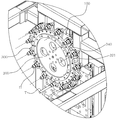
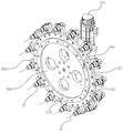
도 2는 도 1의 실시예 중 자동공구 교환장치용 툴매거진만을 도시한 사시도이며,
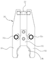
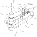
도 3은 도 2의 실시예 중 툴홀더가 클램핑된 그립퍼를 도시한 사시도이고,
도 4는 도 3의 실시예에서 툴홀더가 언클램핑되는 과정을 도시한 사시도이며,
도 5는 도 3의 실시예의 평면도이고,
도 6 및 7은 도 5의 실시예에서 툴홀더가 언클램핑되는 과정을 도시한 평면도이며,
도 8은 도 2의 실시예를 기준으로 공구교환과정을 도시한 측단면도이고,
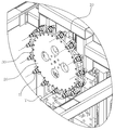
도 9는 머시닝센터에 설치된 본 발명에 따른 자동공구 교환장치용 툴매거진의 일 실시예를 도시한 사시도이며,
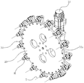
도 10은 도 9의 실시예 중 자동공구 교환장치용 툴매거진만을 도시한 사시도이고,
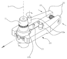
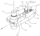
도 11은 도 10의 실시예 중 툴홀더가 클램핑된 그립퍼를 도시한 사시도이며,
도 12는 도 11의 실시예에서 툴홀더가 언클램핑되는 과정을 도시한 사시도이고,
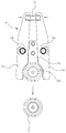
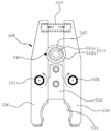
도 13은 도 11의 실시예의 평면도이며,
도 14 및 15는 도 13의 실시예에서 툴홀더가 언클램핑되는 과정을 도시한 평면도이고,
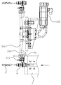
도 16은 도 10의 실시예의 측단면도이며,
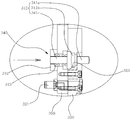
도 17 내지 20은 도 16의 실시예를 기준으로 공구교환과정을 도시한 측단면도 및 요부 측단면도이다.1 is a perspective view showing a tool magazine for an automatic tool changer according to the prior art installed in a machining center,
FIG. 2 is a perspective view showing only a tool magazine for an automatic tool changer in the embodiment of FIG. 1,
FIG. 3 is a perspective view showing a gripper in which the tool holder is clamped in the embodiment of FIG. 2,
4 is a perspective view showing a process of unclamping a tool holder in the embodiment of FIG. 3,
Figure 5 is a plan view of the embodiment of Figure 3,
FIGS. 6 and 7 are plan views showing a process in which the tool holder is unclamped in the embodiment of FIG. 5,
FIG. 8 is a side cross-sectional view showing a tool changing process based on the embodiment of FIG. 2,
9 is a perspective view showing an embodiment of a tool magazine for an automatic tool changer according to the present invention installed in a machining center,
FIG. 10 is a perspective view showing only a tool magazine for an automatic tool changer in the embodiment of FIG. 9,
11 is a perspective view showing a gripper in which the tool holder is clamped in the embodiment of FIG. 10,
12 is a perspective view showing a process in which the tool holder is unclamped in the embodiment of FIG. 11,
Figure 13 is a plan view of the embodiment of Figure 11,
Figs. 14 and 15 are plan views showing a process in which the tool holder is unclamped in the embodiment of Fig. 13,
Figure 16 is a side cross-sectional view of the embodiment of Figure 10,
17 to 20 are a side sectional view and a recessed side sectional view showing a tool changing process based on the embodiment of Fig.
이하에서는 첨부된 도면을 참조로 본 발명에 따른 자동공구 교환장치용 툴매거진의 바람직한 실시예를 상세히 설명한다.
Hereinafter, a preferred embodiment of a tool magazine for an automatic tool changer according to the present invention will be described in detail with reference to the accompanying drawings.
본 발명에 따른 자동공구 교환장치용 툴매거진은, 도 9 내지 20에 도시된 바와 같이 회전모터(100), 매거진플레이트(200) 및 그립퍼(300)를 포함하고, 상기 그립퍼(300)는 키블럭(310), 그립부재(320), 그립스프링(330) 및 그립해제구속부(340)를 포함하여 이루어진다. 상기 그립해제구속부(340)는 슬라이더(341), 가이드시트(342) 및 구속스프링(343)을 포함할 수 있다.A tool magazine for an automatic tool changer according to the present invention includes a
회전모터(100)는 도 9 및 10에 도시된 바와 같이 명칭 그대로 회전력을 발생하는 전동모터로서, 후술하는 매거진플레이트(200)에 회전력을 제공한다. 이때, 회전모터(100)의 회전력을 매거진플레이트(200)에 전달하기 위하여 동력전달수단(도면부호 미도시)이 구비되는데, 주로 회전모터(100)의 고속 회전을 감속하여 토크를 높이기 위한 감속기어부가 설치된다.The
매거진플레이트(200)는 도 9, 10 및 16에 도시된 바와 같이 상기 회전모터(100)로부터 회전력을 전달받아 회전한다. 매거진플레이트(200)에는 후술하는 복수의 그립퍼(300)가 설치되는데, 회전모터(100)로부터 회전력을 전달받아 매거진플레이트(200)가 회전하여 그립퍼(300)에 클램핑된 공구(T)를 스핀들(S)에 전달하거나 교체하기 위한 교환위치로 회전하게 된다.The
그립퍼(300)는 도 9 내지 16에 도시된 바와 같이 복수가 구비되어 상기 매거진플레이트(200)의 일측면 외주에 방사상 등간격으로 각각 고정 설치되고, 공구(T)가 장착되는 툴홀더(H)를 클램핑 또는 언클램핑한다. 공구(T)는 종류별로 형상이나 크기 및 무게가 다양하므로 이러한 공구(T)는 일정한 크기 및 형상을 가진 툴홀더(H)에 장착되고, 이렇게 공구(T)가 장착된 툴홀더(H)를 상기 그립퍼(300)가 클램핑하여 상기 매거진플레이트(200)에 저장해 놓는다. 이후, 가공시 필요한 공구(T)가 장착된 그립퍼(300)를 교환위치로 회전시킨 후 스핀들(S)에 전달하거나 교체하기 위해 그립퍼(300)가 툴홀더(H)를 언클램핑하는 것이다.As shown in FIGS. 9 to 16, the
상기 그립퍼(300) 각각은, 도 11 내지 16에 도시된 바와 같이 키블럭(310), 그립부재(320), 그립스프링(330) 및 그립해제구속부(340)를 포함하여 이루어진다. 키블럭(310)은 상기 매거진플레이트(200)에 고정 설치되며, 상기 그립부재(320)는 한 쌍이 구비되어 상기 매거진플레이트(200)의 일측면에 회전축핀(321)을 통해 각각 회전가능하게 설치되고, 각각의 일단에 상기 키블럭(310)을 기준으로 상기 툴홀더(H)를 클램핑할 수 있는 클램핑요홈(322)이 서로 마주보는 방향으로 각각 형성된다.Each of the
이때, 그립스프링(330)은 한 쌍의 상기 그립부재(320)의 타단 사이에 설치되고, 상기 그립부재(320) 각각의 클램핑요홈(322)이 서로 근접하도록 탄성력을 제공한다. 즉, 도 11, 13 및 15에 도시된 바와 같이 그립스프링(330)에 의해 그립부재(320)는 툴홀더(H)를 클램핑하도록 탄성력이 제공되는 상태이다. 반대로, 도 12 및 14에 도시된 바와 같이 상기 그립스프링(330)이 압축되도록 상기 그립부재(320) 각각의 타단을 근접시키면, 바꿔말해서 상기 그립부재(320) 각각의 클램핑요홈(322)을 외력으로 이격시키면 상기 그립부재(320)에 클램핑된 툴홀더(H)는 언클램핑되어 상기 그립부재(320)로부터 이탈된다.At this time, the grip springs 330 are installed between the other ends of the pair of
이 경우, 상기 그립퍼(300)가 키블럭(310), 그립부재(320) 및 그립스프링(330)으로만 이루어진 경우에는 종래와 같이 그립부재(320)에 클램핑된 툴홀더(H)가 그립스프링(330)의 설계된 스프링력 이상으로 원심력을 받을 경우 그립부재(320)로부터 이탈되어 떨어져 나갈 것이다. 따라서, 이를 방지하기 위하여 상기 그립부재(320)에 클램핑된 툴홀더(H)가 스핀들(S)에 교체될 때를 제외하고는, 원심력이 크게 작용하더라도 그립부재(320)로부터 이탈되지 않도록, 즉 클램핑이 해제되지 않도록 할 필요가 있고, 이는 후술하는 그립해제구속부(340)를 통해 달성될 수 있다.In this case, when the
즉, 그립해제구속부(340)는 도 9 내지 20에 도시된 바와 같이 한 쌍의 상기 그립부재(320) 사이에 설치되고, 상기 그립부재(320) 각각의 클램핑요홈(322)이 서로 이격되지 않도록 상기 그립부재(320) 각각의 회전을 구속한다. 보다 구체적으로, 상기 그립해제구속부(340)는 슬라이더(341), 가이드시트(342) 및 구속스프링(343)을 포함한다.9 to 20, the clamp releasing restricting
슬라이더(341)는 도 18 및 20에 도시된 바와 같이 일단의 누름부재(341a)가 상기 그립부재(320) 사이를 관통하여 돌출 형성되고, 중앙의 구속부재(341b)가 한 쌍의 상기 그립부재(320) 사이에 밀착 삽입되며, 타단의 가이드부재(341c)가 상기 매거진플레이트(200)의 일측면으로부터 타측면까지 관통되어 길이방향을 따라 슬라이딩 가능하게 설치된다. 또한, 가이드시트(342)는 상기 매거진플레이트(200)의 타측면에 결합되고, 상기 슬라이더(341)의 가이드부재(341c)가 삽입되어 상기 슬라이더(341)의 슬라이딩을 가이드한다. 이때, 구속스프링(343)은 상기 슬라이더(341)의 구속부재(341b)와 가이드시트(341c) 사이에 설치되어 상기 슬라이더(341)의 구속부재(341b)를 상기 그립부재(320) 각각의 사이에 밀착 삽입되도록 탄성력을 제공한다.The
따라서, 그립해제구속부(340)의 슬라이더(341)가 구속스프링(343)의 스프링력을 받는 동안은 상기 그립부재(320) 각각의 사이에 밀착 삽입되므로 상기 그립부재(320)의 타단 사이에 설치된 그립스프링(330)이 압축되지 못한다. 즉, 상기 그립부재(320) 각각의 클램핑요홈(322) 역시 서로 이격되지 못한 상태로 상기 툴홀더(H)가 그립부재(320)에 클램핑된 상태를 유지하게 되는 것이다.Since the
한편, 상기 슬라이더(341)의 구속부재(341b)는 도 17 내지 20에 도시된 바와 같이 상기 그립부재(320) 각각의 밀착 삽입되는 면에 외주면이 경사진 원뿔대 형상으로 밀착 삽입된다. 구속부재(341b)가 원뿔대 형상일 경우, 첫째 그립부재(320) 사이로 밀착 삽입되기가 용이하고, 둘째 슬라이더(341)의 누름부재(341a)의 누름작동에 따라 슬라이딩될 때, 그립부재(320) 사이로부터 이탈되기가 용이해지기 때문이다. 이때, 상기 슬라이더(341)의 구속부재(341b)는 원뿔대 형상의 외주면에 단차가 형성되고, 상기 그립부재(320) 각각은, 상기 구속부재(341b)의 외주면과 밀착 삽입되는 면에 형합되는 단차면(323)이 형성될 수도 있다. 이러한 구속부재(341b)의 단차와 그립부재(320)의 단차면(323)은 상술한 삽입 및 이탈의 용이성은 가지되, 단차를 통해 슬라이딩에 대한 가이드기능과 그립부재(320)의 회전구속은 보다 강화할 수 있는 기능을 가지기 위한 것이다.17 to 20, the outer circumferential surface of the restricting
그에 따라, 상기 그립해제구속부(340)는 도 16, 19 및 20에 도시된 바와 같이 상기 슬라이더(341)의 구속부재(341b)가 상기 그립부재(320) 각각의 사이에 밀착 삽입된 경우 상기 그립부재(320) 각각의 클램핑요홈(322)이 서로 이격되지 않도록 상기 그립부재(320) 각각의 회전을 구속하고, 도 17 및 18에 도시된 바와 같이 상기 슬라이더(341)의 누름부재(341a)가 상기 가이드부재(341c) 방향으로 눌러지면서 상기 슬라이더(341)의 구속부재(341b)가 상기 그립부재(320) 각각의 사이로부터 이탈된 경우 상기 그립부재(320) 각각의 클램핑요홈(322)이 서로 근접될 수 있도록 상기 그립부재(320) 각각의 회전구속이 해제된다.16, 19, and 20, when the restricting
상술한 바와 같이 본 발명에 따른 자동공구 교환장치용 툴매거진은, 매거진플레이트(200)의 직경을 키워 많은 양의 공구(T)를 설치하거나, 매거진플레이트(200)의 회전속도를 높일 경우 그립퍼(300)에 클램핑된 툴홀더(H)에 가해지는 원심력이 커지더라도 그립해제구속부(340)를 통하여 툴홀더(H)가 그립퍼(300)로부터 이탈되지 않아 비절삭시간의 단축을 꾀해 가공 생산성을 획기적으로 향상시킬 수 있다.
As described above, the tool magazine for the automatic tool changer according to the present invention is configured such that a large amount of tools T are installed by increasing the diameter of the
앞에서 설명되고, 도면에 도시된 본 발명의 실시예는, 본 발명의 기술적 사상을 한정하는 것으로 해석되어서는 안 된다. 본 발명의 보호범위는 청구범위에 기재된 사항에 의하여만 제한되고, 본 발명의 기술분야에서 통상의 지식을 가진 자는 본 발명의 기술적 사상을 다양한 형태로 개량 변경하는 것이 가능하다. 따라서 이러한 개량 및 변경은 통상의 지식을 가진 자에게 자명한 것인 한 본 발명의 보호범위에 속하게 될 것이다.
The embodiments of the present invention described above and shown in the drawings should not be construed as limiting the technical idea of the present invention. The scope of protection of the present invention is limited only by the matters described in the claims, and those skilled in the art will be able to modify the technical idea of the present invention in various forms. Accordingly, such improvements and modifications will fall within the scope of the present invention as long as they are obvious to those skilled in the art.
T : 공구
H : 툴홀더
S : 스핀들
100 : 회전모터
200 : 매거진플레이트
300 : 그립퍼
310 : 키블럭
320 : 그립부재
321 : 회전축핀
322 : 클램핑요홈
323 : 단차면
330 : 그립스프링
340 : 그립해제구속부
341 : 슬라이더
341a : 누름부재
341b : 구속부재
341c : 가이드부재
342 : 가이드시트
343 : 구속스프링T: Tools
H: Tool holder
S: Spindle
100: Rotary motor
200: Magazine plate
300: gripper 310: key block
320: grip member 321: rotary shaft pin
322: clamping groove 323: stepped surface
330: a grip spring 340: a grip releasing restricting portion
341:
341b:
342: guide seat 343: restraint spring
Claims (5)
상기 회전모터로부터 회전력을 전달받아 회전하는 매거진플레이트와,
상기 매거진플레이트의 일측면 외주에 방사상 등간격으로 각각 고정 설치되고, 공구가 장착되는 툴홀더를 클램핑 또는 언클램핑하는 복수의 그립퍼를 포함하고,
상기 그립퍼 각각은,
상기 매거진플레이트에 고정 설치되는 키블럭과,
상기 매거진플레이트의 일측면에 회전축핀을 통해 각각 회전가능하게 설치되고, 각각의 일단에 상기 키블럭을 기준으로 상기 툴홀더를 클램핑할 수 있는 클램핑요홈이 서로 마주보는 방향으로 각각 형성된 한 쌍의 그립부재와,
한 쌍의 상기 그립부재의 타단 사이에 설치되고, 상기 그립부재 각각의 클램핑요홈이 서로 근접하도록 탄성력을 제공하는 그립스프링과,
한 쌍의 상기 그립부재 사이에 설치되고, 상기 그립부재 각각의 클램핑요홈이 서로 이격되지 않도록 상기 그립부재 각각의 회전을 구속하는 그립해제구속부를 포함하여 이루어진 자동공구 교환장치용 툴매거진.
A rotating motor,
A magazine plate rotatably receiving rotation of the rotation motor,
And a plurality of grippers fixedly mounted on the outer circumference of one side of the magazine plate at equal radial intervals and clamping or unclamping a tool holder on which the tool is mounted,
Each of the grippers
A key block fixed to the magazine plate,
A pair of grips formed on one side of the magazine plate so as to be rotatable through a rotary shaft pin and each having clamping grooves capable of clamping the tool holder with respect to the key block, A member,
A grip spring provided between the other ends of the pair of grip members and providing an elastic force such that the clamping grooves of the grip members are close to each other,
And a grip releasing restricting portion provided between a pair of the grip members and restricting rotation of each of the grip members so that the clamping grooves of the grip members are not separated from each other.
상기 그립해제구속부는,
일단의 누름부재가 상기 그립부재 사이를 관통하여 돌출 형성되고, 중앙의 구속부재가 한 쌍의 상기 그립부재 사이에 밀착 삽입되며, 타단의 가이드부재가 상기 매거진플레이트의 일측면으로부터 타측면까지 관통되어 길이방향을 따라 슬라이딩 가능하게 설치된 슬라이더와,
상기 매거진플레이트의 타측면에 결합되고, 상기 슬라이더의 가이드부재가 삽입되어 상기 슬라이더의 슬라이딩을 가이드하는 가이드시트와,
상기 슬라이더의 구속부재와 가이드시트 사이에 설치되어 상기 슬라이더의 구속부재를 상기 그립부재 각각의 사이에 밀착 삽입되도록 탄성력을 제공하는 구속스프링을 포함하는 것을 특징으로 하는 자동공구 교환장치용 툴매거진.
The method according to claim 1,
The grip releasing /
A pair of pressing members protrude through the gap between the grip members, a central restraining member is closely inserted between the pair of grip members, and the other guide member is passed from one side of the magazine plate to the other side A slider provided slidably along the longitudinal direction,
A guide sheet coupled to the other side surface of the magazine plate and guiding the sliding of the slider by inserting a guide member of the slider,
And a restraining spring provided between the restraint member of the slider and the guide seat to provide an elastic force so that the restraint member of the slider is closely inserted between the grip members.
상기 슬라이더의 구속부재는,
상기 그립부재 각각의 밀착 삽입되는 면에 외주면이 경사진 원뿔대 형상으로 밀착 삽입되는 것을 특징으로 하는 자동공구 교환장치용 툴매거진.
3. The method of claim 2,
The restricting member of the slider
And the outer circumferential surface of the tool magazine is closely inserted into an oblique truncated conical shape on a surface of each of the grip members to be closely inserted.
상기 슬라이더의 구속부재는,
원뿔대 형상의 외주면에 단차가 형성되고,
상기 그립부재 각각은,
상기 구속부재의 외주면과 밀착 삽입되는 면에 형합되는 단차면이 형성된 것을 특징으로 하는 자동공구 교환장치용 툴매거진.
The method of claim 3,
The restricting member of the slider
A step is formed on the outer peripheral surface of the truncated cone,
Wherein each of the grip members comprises:
And a stepped surface that is formed on a surface to be closely inserted into the outer peripheral surface of the restricting member is formed.
상기 그립해제구속부는,
상기 슬라이더의 구속부재가 상기 그립부재 각각의 사이에 밀착 삽입된 경우 상기 그립부재 각각의 클램핑요홈이 서로 이격되지 않도록 상기 그립부재 각각의 회전을 구속하고,
상기 슬라이더의 누름부재가 상기 가이드부재 방향으로 눌러지면서 상기 슬라이더의 구속부재가 상기 그립부재 각각의 사이로부터 이탈된 경우 상기 그립부재 각각의 클램핑요홈이 서로 근접될 수 있도록 상기 그립부재 각각의 회전구속이 해제되는 것을 특징으로 하는 자동공구 교환장치용 툴매거진.5. The method according to any one of claims 2 to 4,
The grip releasing /
When the restraint member of the slider is closely inserted between the grip members, restricting the rotation of each of the grip members so that the clamping grooves of the grip members are not separated from each other,
When the pressing member of the slider is pushed in the direction of the guide member, when the restricting member of the slider is separated from each of the grip members, rotational constraint of each of the grip members is such that the clamping grooves of the respective grip members are brought close to each other The tool magazine is released.
Priority Applications (1)
| Application Number | Priority Date | Filing Date | Title |
|---|---|---|---|
| KR1020150032587A KR101705436B1 (en) | 2015-03-09 | 2015-03-09 | Tool magazine for automatic tool changer |
Applications Claiming Priority (1)
| Application Number | Priority Date | Filing Date | Title |
|---|---|---|---|
| KR1020150032587A KR101705436B1 (en) | 2015-03-09 | 2015-03-09 | Tool magazine for automatic tool changer |
Publications (2)
| Publication Number | Publication Date |
|---|---|
| KR20160109005A true KR20160109005A (en) | 2016-09-21 |
| KR101705436B1 KR101705436B1 (en) | 2017-02-09 |
Family
ID=57080208
Family Applications (1)
| Application Number | Title | Priority Date | Filing Date |
|---|---|---|---|
| KR1020150032587A Expired - Fee Related KR101705436B1 (en) | 2015-03-09 | 2015-03-09 | Tool magazine for automatic tool changer |
Country Status (1)
| Country | Link |
|---|---|
| KR (1) | KR101705436B1 (en) |
Cited By (10)
| Publication number | Priority date | Publication date | Assignee | Title |
|---|---|---|---|---|
| CN107598638A (en) * | 2017-11-02 | 2018-01-19 | 德大机械(昆山)有限公司 | A kind of first quarter moon formula magazine tool structure |
| CN108556053A (en) * | 2018-04-24 | 2018-09-21 | 温岭市六菱机械有限公司 | Automatic cutting means and automatic cutting device |
| KR20190083104A (en) | 2018-01-03 | 2019-07-11 | 두산공작기계 주식회사 | Tool magazine of machine tool |
| CN110712054A (en) * | 2019-11-19 | 2020-01-21 | 皖西学院 | Clamping device for machining |
| CN111331535A (en) * | 2020-03-27 | 2020-06-26 | 湖南机电职业技术学院 | A universal fixture for assembly |
| CN113305578A (en) * | 2021-05-13 | 2021-08-27 | 深圳市宝裕达科技有限公司 | Nine vertical carving of multistation mill |
| KR20210111551A (en) | 2020-03-03 | 2021-09-13 | 두산공작기계 주식회사 | Tool magazine of machine tool and method for operating the same |
| KR20220021405A (en) * | 2020-08-13 | 2022-02-22 | (주) 피엔피 | Auto Tool Change Device for Ultra Thin Glass Block Cutting |
| CN114131393A (en) * | 2020-04-02 | 2022-03-04 | 广东原点智能技术有限公司 | Elastic cutter clamping mechanism |
| CN117817755A (en) * | 2024-03-05 | 2024-04-05 | 洛阳佰工工业密封有限公司 | Cutting device and cutting method for composite gasket |
Families Citing this family (1)
| Publication number | Priority date | Publication date | Assignee | Title |
|---|---|---|---|---|
| CN111975425A (en) * | 2020-08-21 | 2020-11-24 | 浙大城市学院 | High-stability rotary indexing mechanism for tool magazine |
Citations (3)
| Publication number | Priority date | Publication date | Assignee | Title |
|---|---|---|---|---|
| JPH05261640A (en) * | 1991-09-09 | 1993-10-12 | Maho Ag | Tool gripper |
| JPH08108332A (en) * | 1994-10-07 | 1996-04-30 | Brother Ind Ltd | Magazine device for tool change of machine tools |
| KR20110069933A (en) * | 2009-12-18 | 2011-06-24 | 두산인프라코어 주식회사 | Tool magazine of machine tool |
-
2015
- 2015-03-09 KR KR1020150032587A patent/KR101705436B1/en not_active Expired - Fee Related
Patent Citations (3)
| Publication number | Priority date | Publication date | Assignee | Title |
|---|---|---|---|---|
| JPH05261640A (en) * | 1991-09-09 | 1993-10-12 | Maho Ag | Tool gripper |
| JPH08108332A (en) * | 1994-10-07 | 1996-04-30 | Brother Ind Ltd | Magazine device for tool change of machine tools |
| KR20110069933A (en) * | 2009-12-18 | 2011-06-24 | 두산인프라코어 주식회사 | Tool magazine of machine tool |
Cited By (13)
| Publication number | Priority date | Publication date | Assignee | Title |
|---|---|---|---|---|
| CN107598638A (en) * | 2017-11-02 | 2018-01-19 | 德大机械(昆山)有限公司 | A kind of first quarter moon formula magazine tool structure |
| KR20190083104A (en) | 2018-01-03 | 2019-07-11 | 두산공작기계 주식회사 | Tool magazine of machine tool |
| CN108556053A (en) * | 2018-04-24 | 2018-09-21 | 温岭市六菱机械有限公司 | Automatic cutting means and automatic cutting device |
| CN108556053B (en) * | 2018-04-24 | 2024-04-19 | 嘉兴品源科技股份有限公司 | Automatic cutting device and automatic cutting equipment |
| CN110712054A (en) * | 2019-11-19 | 2020-01-21 | 皖西学院 | Clamping device for machining |
| KR20210111551A (en) | 2020-03-03 | 2021-09-13 | 두산공작기계 주식회사 | Tool magazine of machine tool and method for operating the same |
| CN111331535A (en) * | 2020-03-27 | 2020-06-26 | 湖南机电职业技术学院 | A universal fixture for assembly |
| CN111331535B (en) * | 2020-03-27 | 2021-04-06 | 湖南机电职业技术学院 | Universal clamp for assembly |
| CN114131393A (en) * | 2020-04-02 | 2022-03-04 | 广东原点智能技术有限公司 | Elastic cutter clamping mechanism |
| KR20220021405A (en) * | 2020-08-13 | 2022-02-22 | (주) 피엔피 | Auto Tool Change Device for Ultra Thin Glass Block Cutting |
| CN113305578A (en) * | 2021-05-13 | 2021-08-27 | 深圳市宝裕达科技有限公司 | Nine vertical carving of multistation mill |
| CN117817755A (en) * | 2024-03-05 | 2024-04-05 | 洛阳佰工工业密封有限公司 | Cutting device and cutting method for composite gasket |
| CN117817755B (en) * | 2024-03-05 | 2024-05-17 | 洛阳佰工工业密封有限公司 | Cutting device and cutting method for composite gasket |
Also Published As
| Publication number | Publication date |
|---|---|
| KR101705436B1 (en) | 2017-02-09 |
Similar Documents
| Publication | Publication Date | Title |
|---|---|---|
| KR101705436B1 (en) | Tool magazine for automatic tool changer | |
| KR102391258B1 (en) | Machine tool | |
| WO2017176607A1 (en) | Workholding arbor for gears | |
| KR101672322B1 (en) | Fixed-address type automatic tool changer for vertical type machining center | |
| KR102102466B1 (en) | Multitasking machining center with large capacity tool magazine | |
| KR101705327B1 (en) | Tool magazine for automatic tool changer | |
| KR20090106230A (en) | Automatic Discharge Chuck for Lathe | |
| US3874071A (en) | Machine tool with automatic tool changing device | |
| EP3513905B1 (en) | Spindle apparatus for use in machine tool, in particular a lathe, and machine tool with such spindle apparatus | |
| KR20150097468A (en) | Process for machining cross pin on lathes | |
| CN103433572A (en) | Elastic tap chuck | |
| CN203557171U (en) | Novel positioning device of turbocharger middle body on digital controlled lathe | |
| KR20150004763A (en) | Auto tools change with space allowance for tool rejection of spindle | |
| JP7042267B2 (en) | Tapping machine for threading metal nuts with centering equipment | |
| US3131946A (en) | Draw-bar actuated centering device | |
| KR200472903Y1 (en) | Soft jaw for manufacturing ring | |
| US4359814A (en) | Machine tool with automatic tool changing | |
| KR101713106B1 (en) | Tool magazine for automatic tool changer | |
| KR20190126850A (en) | Tools, machines and methods for creating ridge-shaped sharp points on the teeth of a toothed wheel with internal teeth and external teeth | |
| JP7777643B2 (en) | Numerically controlled machine tool with multi-spindle turret and tool gripping device | |
| JP5445544B2 (en) | Composite lathe and composite machining method | |
| JP7213114B2 (en) | Toolholders and machine tools | |
| KR102200029B1 (en) | Automatic tool changer having extended containing structure for machining center | |
| KR101016580B1 (en) | Tool magazine | |
| JP4765790B2 (en) | Grinding wheel attachment / detachment structure |
Legal Events
| Date | Code | Title | Description |
|---|---|---|---|
| A201 | Request for examination | ||
| PA0109 | Patent application |
St.27 status event code: A-0-1-A10-A12-nap-PA0109 |
|
| PA0201 | Request for examination |
St.27 status event code: A-1-2-D10-D11-exm-PA0201 |
|
| D13-X000 | Search requested |
St.27 status event code: A-1-2-D10-D13-srh-X000 |
|
| D14-X000 | Search report completed |
St.27 status event code: A-1-2-D10-D14-srh-X000 |
|
| P22-X000 | Classification modified |
St.27 status event code: A-2-2-P10-P22-nap-X000 |
|
| PG1501 | Laying open of application |
St.27 status event code: A-1-1-Q10-Q12-nap-PG1501 |
|
| E902 | Notification of reason for refusal | ||
| PE0902 | Notice of grounds for rejection |
St.27 status event code: A-1-2-D10-D21-exm-PE0902 |
|
| E13-X000 | Pre-grant limitation requested |
St.27 status event code: A-2-3-E10-E13-lim-X000 |
|
| P11-X000 | Amendment of application requested |
St.27 status event code: A-2-2-P10-P11-nap-X000 |
|
| P13-X000 | Application amended |
St.27 status event code: A-2-2-P10-P13-nap-X000 |
|
| E701 | Decision to grant or registration of patent right | ||
| GRNT | Written decision to grant | ||
| PE0701 | Decision of registration |
St.27 status event code: A-1-2-D10-D22-exm-PE0701 |
|
| PR0701 | Registration of establishment |
St.27 status event code: A-2-4-F10-F11-exm-PR0701 |
|
| PR1002 | Payment of registration fee |
St.27 status event code: A-2-2-U10-U11-oth-PR1002 Fee payment year number: 1 |
|
| PG1601 | Publication of registration |
St.27 status event code: A-4-4-Q10-Q13-nap-PG1601 |
|
| P22-X000 | Classification modified |
St.27 status event code: A-4-4-P10-P22-nap-X000 |
|
| FPAY | Annual fee payment |
Payment date: 20191128 Year of fee payment: 4 |
|
| PR1001 | Payment of annual fee |
St.27 status event code: A-4-4-U10-U11-oth-PR1001 Fee payment year number: 4 |
|
| PR1001 | Payment of annual fee |
St.27 status event code: A-4-4-U10-U11-oth-PR1001 Fee payment year number: 5 |
|
| PR1001 | Payment of annual fee |
St.27 status event code: A-4-4-U10-U11-oth-PR1001 Fee payment year number: 6 |
|
| R18-X000 | Changes to party contact information recorded |
St.27 status event code: A-5-5-R10-R18-oth-X000 |
|
| PR1001 | Payment of annual fee |
St.27 status event code: A-4-4-U10-U11-oth-PR1001 Fee payment year number: 7 |
|
| PR1001 | Payment of annual fee |
St.27 status event code: A-4-4-U10-U11-oth-PR1001 Fee payment year number: 8 |
|
| PC1903 | Unpaid annual fee |
St.27 status event code: A-4-4-U10-U13-oth-PC1903 Not in force date: 20250204 Payment event data comment text: Termination Category : DEFAULT_OF_REGISTRATION_FEE |
|
| H13 | Ip right lapsed |
Free format text: ST27 STATUS EVENT CODE: N-4-6-H10-H13-OTH-PC1903 (AS PROVIDED BY THE NATIONAL OFFICE); TERMINATION CATEGORY : DEFAULT_OF_REGISTRATION_FEE Effective date: 20250204 |
|
| PC1903 | Unpaid annual fee |
St.27 status event code: N-4-6-H10-H13-oth-PC1903 Ip right cessation event data comment text: Termination Category : DEFAULT_OF_REGISTRATION_FEE Not in force date: 20250204 |