KR20170077149A - Slag discharge apparatus and slag discharge method - Google Patents
Slag discharge apparatus and slag discharge method Download PDFInfo
- Publication number
- KR20170077149A KR20170077149A KR1020177012405A KR20177012405A KR20170077149A KR 20170077149 A KR20170077149 A KR 20170077149A KR 1020177012405 A KR1020177012405 A KR 1020177012405A KR 20177012405 A KR20177012405 A KR 20177012405A KR 20170077149 A KR20170077149 A KR 20170077149A
- Authority
- KR
- South Korea
- Prior art keywords
- slag
- screen
- spreader
- water flow
- crushing
- Prior art date
- Legal status (The legal status is an assumption and is not a legal conclusion. Google has not performed a legal analysis and makes no representation as to the accuracy of the status listed.)
- Ceased
Links
- 239000002893 slag Substances 0.000 title claims abstract description 238
- 238000000034 method Methods 0.000 title claims description 21
- XLYOFNOQVPJJNP-UHFFFAOYSA-N water Substances O XLYOFNOQVPJJNP-UHFFFAOYSA-N 0.000 claims abstract description 92
- 239000000446 fuel Substances 0.000 claims abstract description 10
- OKTJSMMVPCPJKN-UHFFFAOYSA-N Carbon Chemical compound [C] OKTJSMMVPCPJKN-UHFFFAOYSA-N 0.000 claims abstract description 9
- 229910052799 carbon Inorganic materials 0.000 claims abstract description 9
- 238000002309 gasification Methods 0.000 claims description 31
- 238000007599 discharging Methods 0.000 claims description 21
- 239000007788 liquid Substances 0.000 claims description 21
- 238000000638 solvent extraction Methods 0.000 claims description 4
- 238000005507 spraying Methods 0.000 abstract description 5
- 239000007789 gas Substances 0.000 description 15
- 238000010926 purge Methods 0.000 description 12
- 239000003245 coal Substances 0.000 description 9
- 238000004132 cross linking Methods 0.000 description 5
- 230000004048 modification Effects 0.000 description 4
- 238000012986 modification Methods 0.000 description 4
- 239000002245 particle Substances 0.000 description 4
- 230000001360 synchronised effect Effects 0.000 description 4
- 238000009825 accumulation Methods 0.000 description 3
- 239000003034 coal gas Substances 0.000 description 3
- XKRFYHLGVUSROY-UHFFFAOYSA-N Argon Chemical compound [Ar] XKRFYHLGVUSROY-UHFFFAOYSA-N 0.000 description 2
- 239000003610 charcoal Substances 0.000 description 2
- 238000010276 construction Methods 0.000 description 2
- 238000005192 partition Methods 0.000 description 2
- 239000000843 powder Substances 0.000 description 2
- 230000000630 rising effect Effects 0.000 description 2
- IJGRMHOSHXDMSA-UHFFFAOYSA-N Atomic nitrogen Chemical compound N#N IJGRMHOSHXDMSA-UHFFFAOYSA-N 0.000 description 1
- 239000007864 aqueous solution Substances 0.000 description 1
- 229910052786 argon Inorganic materials 0.000 description 1
- 239000010426 asphalt Substances 0.000 description 1
- 239000011335 coal coke Substances 0.000 description 1
- 238000002485 combustion reaction Methods 0.000 description 1
- 230000008878 coupling Effects 0.000 description 1
- 238000010168 coupling process Methods 0.000 description 1
- 238000005859 coupling reaction Methods 0.000 description 1
- 230000008021 deposition Effects 0.000 description 1
- 229910001873 dinitrogen Inorganic materials 0.000 description 1
- 238000007667 floating Methods 0.000 description 1
- 239000012530 fluid Substances 0.000 description 1
- 239000011261 inert gas Substances 0.000 description 1
- 239000000463 material Substances 0.000 description 1
- 239000004058 oil shale Substances 0.000 description 1
- 239000007800 oxidant agent Substances 0.000 description 1
- 239000002006 petroleum coke Substances 0.000 description 1
- 239000011295 pitch Substances 0.000 description 1
- 239000000243 solution Substances 0.000 description 1
- 239000007921 spray Substances 0.000 description 1
- 230000007480 spreading Effects 0.000 description 1
Images









Classifications
-
- C—CHEMISTRY; METALLURGY
- C10—PETROLEUM, GAS OR COKE INDUSTRIES; TECHNICAL GASES CONTAINING CARBON MONOXIDE; FUELS; LUBRICANTS; PEAT
- C10J—PRODUCTION OF PRODUCER GAS, WATER-GAS, SYNTHESIS GAS FROM SOLID CARBONACEOUS MATERIAL, OR MIXTURES CONTAINING THESE GASES; CARBURETTING AIR OR OTHER GASES
- C10J3/00—Production of combustible gases containing carbon monoxide from solid carbonaceous fuels
- C10J3/46—Gasification of granular or pulverulent flues in suspension
- C10J3/48—Apparatus; Plants
- C10J3/52—Ash-removing devices
-
- C—CHEMISTRY; METALLURGY
- C10—PETROLEUM, GAS OR COKE INDUSTRIES; TECHNICAL GASES CONTAINING CARBON MONOXIDE; FUELS; LUBRICANTS; PEAT
- C10J—PRODUCTION OF PRODUCER GAS, WATER-GAS, SYNTHESIS GAS FROM SOLID CARBONACEOUS MATERIAL, OR MIXTURES CONTAINING THESE GASES; CARBURETTING AIR OR OTHER GASES
- C10J3/00—Production of combustible gases containing carbon monoxide from solid carbonaceous fuels
- C10J3/46—Gasification of granular or pulverulent flues in suspension
- C10J3/48—Apparatus; Plants
- C10J3/52—Ash-removing devices
- C10J3/523—Ash-removing devices for gasifiers with stationary fluidised bed
-
- C—CHEMISTRY; METALLURGY
- C10—PETROLEUM, GAS OR COKE INDUSTRIES; TECHNICAL GASES CONTAINING CARBON MONOXIDE; FUELS; LUBRICANTS; PEAT
- C10J—PRODUCTION OF PRODUCER GAS, WATER-GAS, SYNTHESIS GAS FROM SOLID CARBONACEOUS MATERIAL, OR MIXTURES CONTAINING THESE GASES; CARBURETTING AIR OR OTHER GASES
- C10J3/00—Production of combustible gases containing carbon monoxide from solid carbonaceous fuels
- C10J3/46—Gasification of granular or pulverulent flues in suspension
-
- C—CHEMISTRY; METALLURGY
- C10—PETROLEUM, GAS OR COKE INDUSTRIES; TECHNICAL GASES CONTAINING CARBON MONOXIDE; FUELS; LUBRICANTS; PEAT
- C10J—PRODUCTION OF PRODUCER GAS, WATER-GAS, SYNTHESIS GAS FROM SOLID CARBONACEOUS MATERIAL, OR MIXTURES CONTAINING THESE GASES; CARBURETTING AIR OR OTHER GASES
- C10J3/00—Production of combustible gases containing carbon monoxide from solid carbonaceous fuels
- C10J3/46—Gasification of granular or pulverulent flues in suspension
- C10J3/48—Apparatus; Plants
- C10J3/52—Ash-removing devices
- C10J3/526—Ash-removing devices for entrained flow gasifiers
-
- C—CHEMISTRY; METALLURGY
- C10—PETROLEUM, GAS OR COKE INDUSTRIES; TECHNICAL GASES CONTAINING CARBON MONOXIDE; FUELS; LUBRICANTS; PEAT
- C10J—PRODUCTION OF PRODUCER GAS, WATER-GAS, SYNTHESIS GAS FROM SOLID CARBONACEOUS MATERIAL, OR MIXTURES CONTAINING THESE GASES; CARBURETTING AIR OR OTHER GASES
- C10J3/00—Production of combustible gases containing carbon monoxide from solid carbonaceous fuels
- C10J3/72—Other features
- C10J3/82—Gas withdrawal means
- C10J3/84—Gas withdrawal means with means for removing dust or tar from the gas
-
- C—CHEMISTRY; METALLURGY
- C10—PETROLEUM, GAS OR COKE INDUSTRIES; TECHNICAL GASES CONTAINING CARBON MONOXIDE; FUELS; LUBRICANTS; PEAT
- C10J—PRODUCTION OF PRODUCER GAS, WATER-GAS, SYNTHESIS GAS FROM SOLID CARBONACEOUS MATERIAL, OR MIXTURES CONTAINING THESE GASES; CARBURETTING AIR OR OTHER GASES
- C10J2300/00—Details of gasification processes
- C10J2300/16—Integration of gasification processes with another plant or parts within the plant
- C10J2300/1625—Integration of gasification processes with another plant or parts within the plant with solids treatment
- C10J2300/1628—Ash post-treatment
- C10J2300/1634—Ash vitrification
-
- C—CHEMISTRY; METALLURGY
- C10—PETROLEUM, GAS OR COKE INDUSTRIES; TECHNICAL GASES CONTAINING CARBON MONOXIDE; FUELS; LUBRICANTS; PEAT
- C10K—PURIFYING OR MODIFYING THE CHEMICAL COMPOSITION OF COMBUSTIBLE GASES CONTAINING CARBON MONOXIDE
- C10K1/00—Purifying combustible gases containing carbon monoxide
- C10K1/08—Purifying combustible gases containing carbon monoxide by washing with liquids; Reviving the used wash liquors
- C10K1/10—Purifying combustible gases containing carbon monoxide by washing with liquids; Reviving the used wash liquors with aqueous liquids
- C10K1/101—Purifying combustible gases containing carbon monoxide by washing with liquids; Reviving the used wash liquors with aqueous liquids with water only
Landscapes
- Chemical & Material Sciences (AREA)
- Engineering & Computer Science (AREA)
- Combustion & Propulsion (AREA)
- Oil, Petroleum & Natural Gas (AREA)
- Organic Chemistry (AREA)
- Gasification And Melting Of Waste (AREA)
- Processing Of Solid Wastes (AREA)
- Disintegrating Or Milling (AREA)
Abstract
슬래그 크러셔(20)는, 탄소 함유 연료를 가스화시키는 가스화 노(10)의 컴버스터에 마련되고, 컴버스터에서 생성되어 낙하한 슬래그를 가스화 노(10)로부터 배출한다. 슬래그 크러셔(20)는, 슬래그의 낙하 방향에 대하여 교차하도록 마련됨과 함께 복수의 개구부(30)를 갖고, 개구부(30)의 직경보다 작은 슬래그를 통과시키는 스크린(22)과, 스크린(22)의 상면을 이동하여, 스크린(22)의 상면에 퇴적된 슬래그를 파쇄하는 스프레더(24)와, 스크린(22)에 퇴적된 슬래그에 대하여 고압수를 분출하는 노즐(26)을 구비한다. 이로써, 스크린(22)의 상면에 퇴적된 슬래그는, 스크린(22)의 개구부(30)로부터 보다 통과하기 쉬워진다.The slag crusher 20 is provided in a combustor of a gasifier 10 for gasifying a carbon-containing fuel, and discharges the slag generated in the combustor 10 from the gasifier 10. The slag crusher 20 includes a screen 22 which is provided so as to intersect the falling direction of the slag and has a plurality of openings 30 and allows slags smaller than the diameter of the openings 30 to pass therethrough, A spreader 24 for moving the upper surface of the screen 22 to crush the slag deposited on the upper surface of the screen 22 and a nozzle 26 for spraying the high pressure water against the slag deposited on the screen 22. As a result, the slag deposited on the upper surface of the screen 22 becomes easier to pass through the opening 30 of the screen 22. [
Description
본 발명은, 슬래그 배출 장치 및 슬래그 배출 방법에 관한 것이다.The present invention relates to a slag discharging device and a slag discharging method.
석탄 등의 탄소 함유 연료를 가스화시키는 가스화 노의 하부에는, 컴버스터에서 생성되어 낙하한 슬래그(용융 슬래그)를 모으는 애시 호퍼가 구비되어 있다(특허문헌 1, 2).In the lower part of a gasification furnace for gasifying a carbon-containing fuel such as coal, there is provided an ash hopper for collecting slag (melted slag) generated in the combustor and falling down (
애시 호퍼에는, 스크린 및 스프레더를 구비하는 슬래그 크러셔가 마련된다. 컴버스터로부터 낙하하는 슬래그는, 물로 급속하게 냉각되어 고화(固化)되어, 슬래그 크러셔가 구비하는 스크린의 상면에 낙하한다.The ash hopper is provided with a slag crusher having a screen and a spreader. The slag falling from the combuster is rapidly cooled with water and solidified, and falls on the upper surface of the screen of the slag crusher.
이 스크린은, 슬래그의 낙하 방향에 대하여 교차하도록 마련됨과 함께 복수의 개구부를 구비하고 있다. 이로써, 스크린은, 개구부의 직경보다 작은 슬래그를 통과시켜, 애시 호퍼의 하부로 낙하시킨다.This screen is provided so as to intersect with the falling direction of the slag and has a plurality of openings. Thereby, the screen is passed through the slag smaller than the diameter of the opening portion, and falls down to the lower portion of the ash hopper.
한편, 스크린의 상면에는, 개구부의 직경보다 큰 슬래그나, 개구부의 직경보다 작은 슬래그의 퇴적인 슬래그 덩어리가 퇴적된다. 슬래그 덩어리는, 슬래그의 입자층 내에서의 마찰력이나 분체압에 의한 가교에 의하여 결합되어 있다.On the other hand, on the upper surface of the screen, a slag larger than the diameter of the opening portion and a slag mass of the slag smaller than the diameter of the opening portion are deposited. The slag agglomerates are bonded by bridging by friction force or powder pressure in the particle layer of the slag.
따라서, 스크린의 상면에 마련된 스프레더가, 예를 들면 유압 실린더에 의하여 스크린의 상면을 이동하여, 스크린의 상면에 퇴적된 슬래그에 힘을 가함으로써 파쇄시켜, 스크린을 통과시킨다.Therefore, the spreader provided on the upper surface of the screen moves on the upper surface of the screen by, for example, a hydraulic cylinder, and is crushed by passing the slag through the screen.
스크린의 개구부로부터 애시 호퍼의 하부로 낙하하여 퇴적된 슬래그는, 가스화 노로부터 록 호퍼를 통하여 계(系) 외로 배출된다.The slag falling and deposited from the opening of the screen to the bottom of the ash hopper is discharged from the gasifier through the lock hopper to the outside of the system.
그러나, 스프레더를 작동시켜도, 퇴적된 슬래그가 파쇄되지 않고, 슬래그 크러셔의 작동 방향으로 긁어모아질 뿐, 스크린을 통과하지 못하는 경우가 있다.However, even when the spreader is operated, the deposited slag is not crushed but scraped in the operating direction of the slag crusher, and may not pass through the screen.
그리고, 스크린의 상면에서의 슬래그의 퇴적량이 많아져, 가스화 노로부터 슬래그가 배출되지 않아, 애시 호퍼 내에 슬래그가 가득 차는 경우가 있다. 이 경우, 가스화 노의 운전 지속이 곤란하게 되어, 가스화 노를 정지시키게 된다.Then, the amount of slag deposited on the upper surface of the screen increases, so that the slag is not discharged from the gasifier and the slag is filled in the ash hopper. In this case, continuous operation of the gasification furnace becomes difficult, and the gasification furnace is stopped.
본 발명은, 이와 같은 사정을 감안하여 이루어진 것이며, 스크린의 상면에 퇴적된 슬래그를 스크린의 개구부로부터 보다 통과하기 쉽게 할 수 있는, 슬래그 배출 장치 및 슬래그 배출 방법을 제공하는 것을 목적으로 한다.SUMMARY OF THE INVENTION It is an object of the present invention to provide a slag discharging device and a slag discharging method which can make slag deposited on an upper surface of a screen easier to pass through an opening of a screen.
상기 과제를 해결하기 위하여, 본 발명의 슬래그 배출 장치 및 슬래그 배출 방법은 이하의 수단을 채용한다.In order to solve the above problems, the slag discharging device and the slag discharging method of the present invention employ the following means.
본 발명의 제1 양태에 관한 슬래그 배출 장치는, 탄소 함유 연료를 가스화시키는 가스화 노의 컴버스터에 마련되고, 상기 컴버스터에서 생성되어 낙하한 슬래그를 상기 가스화 노로부터 배출하는 슬래그 배출 장치로서, 상기 슬래그의 낙하 방향에 대하여 교차하도록 마련됨과 함께 복수의 개구부를 가지며, 상기 개구부의 직경보다 작은 상기 슬래그를 통과시키는 스크린과, 상기 스크린의 상면을 이동하여, 상기 스크린의 상면에 퇴적된 상기 슬래그를 파쇄하는 파쇄 수단과, 상기 스크린에 퇴적된 상기 슬래그에 대하여 액체를 흘려 보내 수류(水流)를 형성하는 수류 형성 수단을 구비한다.The slag discharging device according to the first aspect of the present invention is a slag discharging device provided in a gasifier of a gasification furnace for gasifying a carbon containing fuel and discharging the slag generated in the reclaimer from the gasifier, A screen which is provided so as to cross the falling direction of the slag and which has a plurality of openings and through which the slag is smaller than the diameter of the opening; and an upper surface of the screen, wherein the slag deposited on the upper surface of the screen is crushed And a water flow forming means for forming a water flow by flowing a liquid to the slag deposited on the screen.
본 구성에 관한 슬래그 배출 장치는, 탄소 함유 연료를 가스화시키는 가스화 노의 컴버스터에 마련되고, 컴버스터에서 생성되어 낙하한 슬래그를 가스화 노로부터 배출한다.The slag discharging device according to the present construction is provided in a gasifier furnace for gasifying a carbon-containing fuel, and the slag generated in the combustor and discharged from the gasifier is discharged.
그리고, 슬래그 배출 장치는, 슬래그의 낙하 방향에 대하여 교차하도록 마련됨과 함께 복수의 개구부를 갖는 스크린을 구비한다. 스크린의 개구부의 직경보다 작은 슬래그가 개구부를 통과하여 낙하한다. 한편, 개구부를 통과하지 못하고, 스크린의 상면에 퇴적된 슬래그는, 스크린의 상면을 이동하는 파쇄 수단에 의하여 파쇄된다.The slag discharge device is provided with a screen provided so as to cross the slag falling direction and having a plurality of openings. The slag smaller than the diameter of the opening of the screen falls through the opening. On the other hand, the slag deposited on the upper surface of the screen without passing through the opening is crushed by crushing means moving on the upper surface of the screen.
여기에서, 스크린의 상면에 퇴적되는 슬래그에는, 개구부의 직경보다 작은 슬래그가 마찰력이나 분체압에 의한 가교에 의하여 결합된 슬래그 덩어리가 포함된다.Here, the slag deposited on the upper surface of the screen includes slag agglomerated with slag smaller than the diameter of the opening by bridging by frictional force or bulk pressure.
퇴적되는 슬래그를 제거하기 위하여 수류 형성 수단으로부터, 스크린의 상면에 퇴적된 슬래그에 대하여 액체를 흘려 보내 수류가 형성된다. 가교에 의하여 결합된 슬래그의 입자에 가압된 액체가 분출됨으로써, 가교에 의한 결합이 절단된다. 이로써, 슬래그가 정치(靜置) 상태로부터 완만하게 유동화한다. 또한, 슬래그에 분출되는 액체는, 예를 들면 물이다.In order to remove the deposited slag, a flow of water is formed by flowing a liquid from the water flow forming means to the slag deposited on the upper surface of the screen. The pressurized liquid is ejected to the particles of the slag combined by the crosslinking, whereby the bond due to the crosslinking is broken. Thereby, the slag gently fluidizes from the stationary state. The liquid ejected to the slag is, for example, water.
그리고, 유동하기 쉬워진 슬래그는, 수류 형성 수단으로부터의 액체에 의하여 흘려 보내진다. 이로써, 슬래그는, 파쇄 수단을 이동시키지 않고, 스크린의 개구부로부터 액체와 함께 낙하하게 된다. 또, 슬래그는, 파쇄 수단을 이동시키는 것에 의해서도, 간단하게 개구부로부터 낙하하기 쉬워진다.Then, the slag, which is easy to flow, is flowed by the liquid from the water flow forming means. Thereby, the slag falls with the liquid from the opening of the screen without moving the crushing means. Further, the slag can easily fall from the opening even by moving the crushing means.
이상과 같이, 본 구성은, 스크린의 상면에 퇴적된 슬래그를 스크린의 개구부로부터 보다 통과하기 쉽게 할 수 있다.As described above, this configuration can make the slag deposited on the upper surface of the screen easier to pass through the opening of the screen.
상기 제1 양태에서는, 상기 수류 형성 수단이, 상기 파쇄 수단의 작동 방향에 대하여 나란하게 세워져 마련된 상기 스크린의 측벽에 구비되는 것이 바람직하다.In the first aspect, it is preferable that the water flow forming means is provided on the side wall of the screen provided so as to be parallel to the operating direction of the crushing means.
본 구성에 의하면, 퇴적된 슬래그에 대하여, 가압된 액체를 간단하고 또한 균일하게 분출할 수 있다.According to this configuration, the pressurized liquid can be simply and uniformly ejected to the deposited slag.
상기 제1 양태에서는, 상기 수류 형성 수단이, 상기 파쇄 수단에 구비되는 것이 바람직하다.In the first aspect, it is preferable that the water flow forming means is provided in the crushing means.
본 구성에 의하면, 파쇄 수단에 의하여 파쇄되는 슬래그에 대하여, 보다 확실하게 가압된 액체가 분출되므로, 퇴적된 슬래그의 가교에 의한 결합을 절단하여, 스크린을 슬래그가 통과하기 쉽게 한다.According to this structure, since the liquid pressurized more reliably to the slag to be crushed by the crushing means, the coupling due to the crosslinking of the deposited slag is cut off, and the slag easily passes through the screen.
상기 제1 양태에서는, 상기 파쇄 수단이, 상기 슬래그의 파쇄 방향에 대하여 앞으로 경사진 경사면을 구비하는 것이 바람직하다.In the first aspect, it is preferable that the crushing means has an inclined surface inclined forward with respect to the crushing direction of the slag.
본 구성에 의하면, 퇴적된 슬래그에 대하여 하향으로 힘이 가해지므로, 퇴적된 슬래그의 가교에 의한 결합을 절단하여, 스크린을 슬래그가 통과하기 쉽게 한다.According to this structure, since the force is applied downward to the deposited slag, the bond due to the crosslinking of the deposited slag is cut off, and the slag easily passes through the screen.
상기 제1 양태에서는, 상기 수류 형성 수단이 상기 경사면에 마련되어, 상기 스크린의 방향으로 액체를 분출하는 것이 바람직하다.In the first aspect, it is preferable that the water flow forming means is provided on the inclined surface to eject the liquid in the direction of the screen.
본 구성에 의하면, 파쇄 수단에 의하여 파쇄되는 슬래그에 대하여, 분출되는 액체에 의해서도 하향으로 힘이 가해지므로, 퇴적된 슬래그를 보다 확실하게 파쇄할 수 있다.According to this structure, since the force applied to the slag to be crushed by the crushing means is also applied downward by the liquid to be ejected, the deposited slag can be more reliably crushed.
상기 제1 양태에서는, 상기 수류 형성 수단이, 상기 스크린에 구비되는 것이 바람직하다.In the first aspect, it is preferable that the water flow forming means is provided on the screen.
본 구성에 의하면, 스크린의 상면에서의 슬래그의 퇴적을 억제할 수 있고, 또한 퇴적된 슬래그에 대하여, 가압된 액체를 간단하고 또한 균일하게 분출할 수 있다.According to this structure, deposition of slag on the upper surface of the screen can be suppressed, and the pressurized liquid can be ejected simply and uniformly on the deposited slag.
상기 제1 양태에서는, 상기 수류 형성 수단이, 액체 대신에 기체를 분출하는 것이 바람직하다.In the first aspect, it is preferable that the water flow forming means ejects a gas instead of the liquid.
상기 제1 양태에서는, 상기 파쇄 수단의 이동 방향을 제한하는 가이드를 구비하는 것이 바람직하다.In the first aspect, it is preferable to provide a guide for limiting the moving direction of the crushing means.
본 구성에 의하면, 파쇄 수단이 이동할 때에 있어서의 부상을 방지하는 등, 파쇄 수단의 이동을 안정적으로 할 수 있다.According to this configuration, it is possible to stabilize the movement of the shredding means, for example, to prevent the shredding means from floating.
상기 제1 양태에서는, 상기 스크린의 상면에 복수의 상기 파쇄 수단을 인접하게 구비함과 함께, 인접하는 상기 파쇄 수단의 사이에서 상기 스크린이 구획 수단에 의하여 구획됨으로써 구분되고, 구분된 영역별로 하방에 상기 수류 형성 수단을 구비하는 것이 바람직하다.In the first aspect, a plurality of the crushing means are adjacently provided on the upper surface of the screen, and the screen is divided by the partitioning means between the adjacent crushing means, It is preferable to provide the water flow forming means.
본 구성에 의하면, 수류 형성 수단이 형성하는 수류에 의하여 스크린 상의 슬래그가 흘려 보내지므로, 슬래그가 스크린에 잔류하는 것을 방지할 수 있다.According to this configuration, since the slag on the screen is flowed by the water flow formed by the water flow forming means, it is possible to prevent the slag from remaining on the screen.
상기 제1 양태에서는, 소정의 상기 파쇄 수단을 작동시키기 전에, 상기 소정의 상기 파쇄 수단에 대응하는 상기 영역의 하방에 구비된 상기 수류 형성 수단으로부터의 수류에 의하여, 인접하는 다른 상기 파쇄 수단에 대응하는 상기 영역으로 상기 슬래그를 이동시키는 것이 바람직하다.In the first aspect, the water flow from the water flow forming means provided below the region corresponding to the predetermined crushing means corresponds to the adjacent other crushing means before the predetermined crushing means is operated And the slag is moved to the region where the slag is formed.
본 구성에 의하면, 수류 형성 수단으로부터의 수류에 의하여 상대적으로 작은 슬래그가 다른 파쇄 수단에 대응하는 영역으로 흘려 보내지고 거기에서 스크린으로부터 낙하한다. 그리고, 작동하는 파쇄 수단은, 수류에 의하여 흘려 보내지지 않은 상대적으로 큰 슬래그를 파쇄하므로, 큰 슬래그가 스크린에 잔류하는 것을 방지할 수 있다.According to this configuration, a relatively small slag is caused to flow into the region corresponding to the other crushing means by the water flow from the water flow forming means, and drops from the screen there. And, the working crushing means crushes the relatively large slag not flowed by the water flow, so that the large slag can be prevented from remaining on the screen.
상기 제1 양태에서는, 상기 파쇄 수단의 하단부가, 이동했을 때에 대향하는 면과 폭 방향에 걸쳐 면접촉하도록 형성되는 것이 바람직하다.In the first aspect, it is preferable that the lower end portion of the crushing means is formed so as to be in surface contact with the surface opposed to the crushing means in the width direction.
본 구성에 의하면, 파쇄 수단의 하단부가, 이동했을 때에 대향하는 면과 폭 방향에 걸쳐 면접촉하므로, 파쇄 수단의 하단부와 그 대향면의 사이에 간극이 없어진다. 따라서, 본 구성은, 스크린 상의 슬래그를 보다 확실하게 파쇄할 수 있으므로, 큰 슬래그가 스크린에 잔류하는 것을 방지할 수 있다.According to this configuration, since the lower end portion of the crushing means is in surface contact with the surface opposed to the crushing means when moved, the clearance between the lower end portion of the crushing means and the opposed surface thereof is eliminated. Therefore, this configuration can more reliably crush the slag on the screen, and therefore, it is possible to prevent the large slag from remaining on the screen.
본 구성에 의하면, 스크린의 상면에 물이 공급된 상태에서, 스크린의 상면으로부터 기체가 분출됨으로써, 기포의 상승에 의하여 슬래그의 가교에 의한 결합이 절단된다. 이로써, 슬래그가 유동화되므로, 스크린의 상면에 퇴적된 슬래그는, 스크린의 개구부를 보다 통과하기 쉬워진다.According to this configuration, in the state where water is supplied to the upper surface of the screen, gas is blown from the upper surface of the screen, and the bond due to the bridging of the slag is cut by the rising of the bubbles. Thereby, since the slag is fluidized, the slag deposited on the upper surface of the screen becomes easier to pass through the opening of the screen.
본 발명의 제2 양태에 관한 슬래그 배출 방법은, 탄소 함유 연료를 가스화시키는 가스화 노의 컴버스터에 마련되고, 상기 컴버스터에서 생성되어 낙하한 슬래그를 상기 가스화 노로부터 배출하는 슬래그 배출 장치를 이용한 슬래그 배출 방법으로서, 상기 슬래그의 낙하 방향에 대하여 교차하도록 마련됨과 함께 복수의 개구부를 갖는 스크린의 상면에 퇴적된 슬래그에 대하여, 수류 형성 수단으로부터 액체를 흘려 보내 수류를 형성하는 제1 공정과, 상기 스크린의 상면에 퇴적된 상기 슬래그를 파쇄하는 파쇄 수단이, 상기 스크린의 상면을 이동하는 제2 공정을 포함한다.A slag discharging method according to a second aspect of the present invention is a slag discharging method provided in a gasification furnace of a gasification furnace for gasifying a carbon containing fuel and comprising a slag discharging device for discharging the slag, A first step of flowing water from the water flow forming means to the slag deposited on the upper surface of the screen provided so as to cross the falling direction of the slag and having a plurality of openings to form a water flow; The crushing means for crushing the slag deposited on the upper surface of the screen includes a second step of moving the upper surface of the screen.
본 발명에 의하면, 스크린의 상면에 퇴적된 슬래그를 스크린의 개구부로부터 보다 통과하기 쉽게 할 수 있다는 우수한 효과를 갖는다.According to the present invention, it is possible to make the slag deposited on the upper surface of the screen easier to pass through the opening of the screen.
도 1은 본 발명의 제1 실시형태에 관한 가스화 노의 종단면도이다.
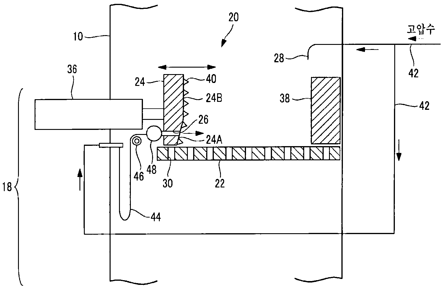
도 2는 본 발명의 제1 실시형태에 관한 슬래그 크러셔의 종단면도이다.
도 3은 본 발명의 제1 실시형태에 관한 스프레더의 정면도이다.
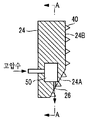
도 4는 본 발명의 제2 실시형태에 관한 스프레더의 측면에서 보았을 때의 종단면도이다.
도 5는 본 발명의 제2 실시형태에 관한 스프레더의 정면에서 보았을 때의 종단면도이다.
도 6은 본 발명의 제3 실시형태에 관한 스크린의 종단면도이다.
도 7은 본 발명의 제3 실시형태의 변형예에 관한 스크린의 종단면도이다.
도 8은 본 발명의 제4 실시형태에 관한 스크린의 종단면도이다.
도 9는 본 발명의 제4 실시형태의 변형예에 관한 스크린의 종단면도이다.
도 10은 본 발명의 제5 실시형태에 관한 슬래그 크러셔의 상면도이다.
도 11은 본 발명의 제5 실시형태에 관한 스크린 및 측벽의 종단면도이다.
도 12는 스프레더의 부상을 설명하기 위한 종단면도이다.
도 13은 본 발명의 제6 실시형태에 관한 슬래그 크러셔의 상면도이다.
도 14는 본 발명의 제6 실시형태에 관한 슬래그 크러셔의 측면에서 보았을 때의 종단면도이다.
도 15는 본 발명의 제6 실시형태에 관한 슬래그 크러셔의 정면에서 보았을 때의 종단면도이다.
도 16은 슬래그의 잔류 상태를 설명하기 위한 측면에서 보았을 때의 종단면도이다.
도 17은 본 발명의 제7 실시형태에 관한 슬래그 크러셔의 측면에서 보았을 때의 종단면도이다.1 is a longitudinal sectional view of a gasification furnace according to a first embodiment of the present invention.
2 is a longitudinal sectional view of a slag crusher according to a first embodiment of the present invention.
3 is a front view of the spreader according to the first embodiment of the present invention.
4 is a longitudinal sectional view of a spreader according to a second embodiment of the present invention.
5 is a longitudinal sectional view of the spreader according to the second embodiment of the present invention when viewed from the front.
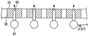
6 is a longitudinal sectional view of a screen according to a third embodiment of the present invention.
7 is a longitudinal sectional view of a screen according to a modification of the third embodiment of the present invention.
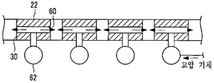
8 is a longitudinal sectional view of a screen according to a fourth embodiment of the present invention.
9 is a longitudinal sectional view of a screen according to a modification of the fourth embodiment of the present invention.
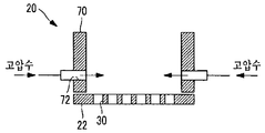
10 is a top view of a slag crusher according to a fifth embodiment of the present invention.
11 is a longitudinal sectional view of a screen and side walls according to a fifth embodiment of the present invention.
12 is a longitudinal sectional view for explaining the spreading of the spreader.
13 is a top view of a slag crusher according to a sixth embodiment of the present invention.
Fig. 14 is a longitudinal sectional view of a slag crusher according to a sixth embodiment of the present invention when viewed from the side; Fig.
15 is a longitudinal sectional view of the slag crusher according to the sixth embodiment of the present invention when viewed from the front;
16 is a longitudinal sectional view showing the residual state of the slag in terms of the side view.
17 is a longitudinal sectional view of a slag crusher according to a seventh embodiment of the present invention when viewed from the side;
이하에, 본 발명에 관한 슬래그 배출 장치 및 슬래그 배출 방법의 일 실시형태에 대하여, 도면을 참조하여 설명한다.Hereinafter, one embodiment of the slag discharging device and the slag discharging method according to the present invention will be described with reference to the drawings.
[제1 실시형태][First Embodiment]
이하, 본 발명의 제1 실시형태에 대하여 설명한다.Hereinafter, a first embodiment of the present invention will be described.
도 1은, 본 제1 실시형태에 관한 가스화 노(10)의 종단면도이다.1 is a longitudinal sectional view of a
본 제1 실시형태에 관한 가스화 노(10)에 적용되는 탄소 함유 연료는, 석탄, 석유 코크스, 석탄 코크스, 아스팔트, 피치, 오일 셰일 등의 중질계 연료 외에, 폐타이어, 플라스틱 등의 폐기물을 일례로서 들 수 있다. 이하의 각 실시형태에서는, 가스화시키는 탄소 함유 연료를 석탄으로 하는 경우에 대하여 설명한다.The carbon-containing fuel to be applied to the
가스화 노(10)에서는, 회융점(灰融點) 이상의 1500~1800℃ 정도의 고온 분위기로 되어 있는 컴버스터(12)에 있어서, 석탄 공급 설비(도시하지 않음)로부터 공급되는 미분탄과, 탈진 장치(도시하지 않음)에서 회수되어 공급되는 차콜이, 산화제와 반응한다. 이로써, 컴버스터(12)에서는, 미분탄이 고온 연소됨으로써, 가연성 가스인 석탄 가스가 생성됨과 함께, 미분탄 중의 회분이 용융한 슬래그(14)가 생성된다.In the
그리고, 컴버스터(12)의 고온 연소에 의하여 얻어진 고온의 석탄 가스가, 컴버스터(12)의 상단에 마련된 리덕터(16)에 흘러들어간다. 이 리덕터(16)에 있어서도, 미분탄과 차콜이 공급되고, 공급된 미분탄 및 차콜이 더욱 가스화되어, 석탄 가스에 의한 가연성 가스가 생성된다. 또한, 본 제1 실시형태에 관한 컴버스터(12)는, 분류상식(噴流床式)이지만, 이에 한정하지 않고, 유동상식이나 고정상식이어도 된다.The high-temperature coal gas obtained by the high-temperature combustion of the
가스화 노(10)의 하부에는, 컴버스터(12)에서 생성되어 낙하한 슬래그(14)를 모으는 애시 호퍼(18)가 구비되어 있다.At the lower portion of the
애시 호퍼(18)에는, 슬래그(14)를 파쇄하여 가스화 노(10)로부터 배출하는 슬래그 크러셔(20)가 마련된다. 또한, 가스화 노(10)의 하부는, 슬래그 크러셔(20)를 구비하는 영역까지, 물로 채워진 상태로 되어 있다.The
도 2는, 본 제1 실시형태에 관한 슬래그 크러셔(20)의 구성을 나타내는 종단면도이다.2 is a longitudinal sectional view showing the construction of the
슬래그 크러셔(20)는, 스크린(22)(크러셔 메시라고도 함), 스프레더(24), 및 노즐(26)을 구비한다.The
컴버스터(12)로부터 낙하하는 슬래그(14)는, 애시 호퍼 급수관(28)으로부터 분출하는 물(이하 "애시 호퍼수"라고 함)로 급속하게 냉각되어 고화되어, 슬래그 크러셔(20)가 구비하는 스크린(22)의 상면에 낙하한다.The
스크린(22)은, 슬래그(14)의 낙하 방향에 대하여 교차하도록 마련됨과 함께 복수의 개구부(30)를 갖고, 개구부(30)의 직경보다 작은 슬래그(14)를 통과시킨다. 스크린(22)은, 개구부(30)를 갖는, 예를 들면 판 형상의 부재이다. 다만, 개구부(30)의 형상은 특별히 한정되지 않고, 예를 들면 원형이나 다각형 등이다.The
개구부(30)를 통과한 슬래그(14)는, 애시 호퍼수와 함께 애시 호퍼(18)의 하부로 낙하한다. 애시 호퍼(18)의 하부에는, 도 1에 나타나는 바와 같이 록 호퍼(34)가 접속되어 있고, 애시 호퍼(18)의 하부로 낙하한 슬래그(14)는, 록 호퍼(34)를 통하여 계 외로 배출된다.The
또한, 도 1의 가스화 노(10)는, 일례로서, 슬래그(14)를 록 호퍼(34)까지 낙하시킴으로써 계 외로 배출하는 중력 낙하 방식을 채용하고 있지만, 이에 한정하지 않으며, 슬래그(14)를 록 호퍼(34)로 낙하시키지 않고, 취출하여 재이용하는 가로 흡출 방식이 채용되어도 된다.The
스프레더(24)는, 유압 실린더(36) 및 가이드 로드(37)에 의하여 스크린(22)의 상면을 이동하여, 스크린(22)의 상면에 퇴적된 슬래그(14)를 파쇄한다. 또한, 도 2에 나타나는 스프레더(24)의 위치는, 스크린(22)의 상면을 이동하기 전의 대기 위치이다.The
스프레더(24)의 대기 위치의 반대측에는, 고정판(38)이 구비된다. 즉, 스프레더(24)는, 대기 위치로부터 고정판(38)까지 이동함으로써, 스크린(22)의 상면에 퇴적된 슬래그(14)를 긁어모은다. 그리고, 스프레더(24)는, 고정판(38)과의 사이에 슬래그(14)를 끼워넣음으로써, 퇴적된 슬래그(14)를 파쇄한다. 또한, 스프레더(24)의 정면에는, 슬래그(14)를 파쇄하기 쉽게 하기 위하여, 돌기물(40)이 마련된다. 또한, 도 2에 나타나는 돌기물(40)은, 일례로서 원뿔 형상이지만, 이에 한정하지 않고, 예를 들면 원뿔대 형상, 다각뿔 형상, 또는 다각뿔대 형상 등이어도 된다.On the opposite side of the standby position of the
또, 본 제1 실시형태에 관한 스프레더(24)는, 슬래그(14)의 파쇄 방향에 대하여 앞으로 경사진 경사면(24A)을 구비한다. 경사면(24A)은, 스프레더(24)의 하부에 마련되어 있다. 스프레더(24)는, 퇴적된 슬래그(14)를 주로 경사면(24A)에 의하여 긁어모으게 된다. 경사면(24A)의 상방은, 스크린(22)에 대하여 수직으로 된 수직면(24B)으로 되어 있다.The
또, 노즐(26)은, 스크린(22)에 퇴적된 슬래그(14)에 대하여 액체를 흘려 보내 수류를 형성하는 수류 형성 수단이며, 구체예로서 가압된 액체를 분출하는 분출 구멍이다. 본 제1 실시형태에 관한 노즐(26)은, 스프레더(24)의 경사면(24A)에 구비된다. 노즐(26)은, 도 3의 스프레더(24)의 정면도에도 나타나는 바와 같이, 일례로서, 경사면(24A)에 수평으로 복수 마련된다.The
노즐(26)로부터 분출되는 가압된 액체는, 일례로서 물이지만, 이에 한정하지 않고, 후술하는 바와 같이 슬래그(14)의 가교를 절단할 수 있는 액체이면 된다. 또, 가압된 물을 이하의 설명에 있어서 고압수라고 호칭한다. 고압수의 압력은, 일례로서 3~5MPa이다.The pressurized liquid ejected from the
애시 호퍼 급수관(28)에 고압수를 공급하는 급수관(42)은, 분기하여 노즐(26)에 접속된다. 보다 구체적으로는, 분기한 급수관(42)은, 고압 호스(44)에 접속된다. 고압 호스(44)는, 스프레더(24)의 이동에 대응하기 위하여 유연성을 갖고 있으며, 고압 호스 지지구(46)에 의하여 지지된다.The
고압 호스(44)는, 고압수 헤더(48)에 접속된다. 고압수 헤더(48)는, 복수의 노즐(26)에 고압수를 공급한다.The
다음으로 본 제1 실시형태에 관한 슬래그 크러셔(20)의 작용에 대하여 설명한다.Next, the operation of the
컴버스터(12)에서 생성된 슬래그(14)는, 스크린(22)의 상면에 낙하한다.The
스크린(22)의 상면에 낙하한 슬래그(14) 중, 스크린(22)의 개구부(30)의 직경보다 작은 슬래그(14)는, 개구부(30)를 통과하여, 애시 호퍼(18)의 하부, 즉 가스화 노(10)의 하부로 낙하한다.The
한편, 개구부(30)의 직경보다 큰 슬래그(14)나, 개구부(30)의 직경보다 작은 슬래그(14)의 퇴적인 슬래그 덩어리는, 개구부(30)를 통과하지 못하고 스크린(22)의 상면에 퇴적된다.On the other hand, the
따라서, 스프레더(24)가 소정의 시간 간격마다 스크린(22)의 상면을 대기 위치로부터 고정판(38)까지 이동시킨다. 이로써, 스프레더(24)가, 퇴적된 슬래그(14)를 파쇄하여, 슬래그(14)를 개구부(30)로부터 통과하기 쉽게 한다.Thus, the
또, 본 제1 실시형태에 관한 스프레더(24)는, 경사면(24A)에 의하여, 퇴적된 슬래그(14)에 대하여 하향으로 힘을 가하므로, 퇴적된 슬래그(14)를 보다 확실하게 파쇄할 수 있다.Since the
그러나, 작은 슬래그(14)가 가교에 의하여 결합된 슬래그 덩어리는, 스프레더(24)에 의해서도 파쇄되지 않아, 개구부(30)를 통과하지 못하고, 스프레더(24)의 이동 방향으로 긁어모아지는 경우가 있다.However, the slag mass in which the
따라서, 스프레더(24)의 경사면(24A)에 구비되는 노즐(26)로부터 슬래그(14)를 향하여 고압수가 분출된다. 가교에 의하여 결합된 슬래그(14)의 입자에 고압수가 분출됨으로써, 가교에 의한 결합이 절단된다. 이로써, 슬래그(14)가 정치 상태로부터 완만하게 유동화한다.Therefore, high pressure water is ejected from the
또, 노즐(26)이 경사면(24A)에 구비됨으로써, 스프레더(24)에 의하여 파쇄되는 슬래그(14)에 대하여, 보다 확실하게 고압수가 분출되므로, 퇴적된 슬래그(14)를 보다 확실하게 파쇄할 수 있다.Further, since the
또한, 노즐(26)로부터의 고압수의 분출은, 스프레더(24)가 이동하는 시간 간격과 동기되어도 되고, 스프레더(24)가 이동하는 시간 간격과 관계없이, 간헐 또는 연속적으로 행해져도 된다.The ejection of the high-pressure water from the
그리고, 유동하기 쉬워진 슬래그(14)는, 노즐(26)로부터 분출되는 고압수에 의하여 흘려 보내진다. 이로써, 슬래그(14)는, 스프레더(24)를 이동시키지 않고, 스크린(22)의 개구부(30)로부터 고압수와 함께 낙하하게 된다. 또, 슬래그(14)는, 스프레더(24)를 이동시키는 것에 의해서도, 간단하게 개구부(30)로부터 낙하하기 쉬워진다.Then, the
이상 설명한 바와 같이, 본 제1 실시형태에 관한 슬래그 크러셔(20)는, 슬래그(14)의 낙하 방향에 대하여 교차하도록 마련됨과 함께 복수의 개구부(30)를 갖고, 개구부(30)의 직경보다 작은 슬래그(14)를 통과시키는 스크린(22)과, 스크린(22)의 상면을 이동하여, 스크린(22)의 상면에 퇴적된 슬래그(14)를 파쇄하는 스프레더(24)와, 스크린(22)에 퇴적된 슬래그(14)에 대하여 고압수를 분출하는 노즐(26)을 구비한다.As described above, the
따라서, 슬래그 크러셔(20)는, 스크린(22)의 상면에 퇴적된 슬래그(14)를 스크린(22)의 개구부(30)로부터 보다 통과하기 쉽게 할 수 있다. 이로써, 슬래그(14)가 스크린(22)의 상면에 퇴적되어도 슬래그 크러셔(20)에 의하여, 보다 확실하게 슬래그(14)의 배출이 가능해진다. 그 결과, 슬래그(14)의 퇴적에 의하여 가스화 노(10)의 운전이 정지되는 것을 억제할 수 있어, 가스화 노(10)의 계속적인 운전이 가능해진다.Therefore, the
또한, 본 제1 실시형태에 관한 슬래그 크러셔(20)는, 스프레더(24)의 경사면(24A)에 노즐(26)을 구비하지만, 이에 한정하지 않고, 스프레더(24)의 수직면(24B)에 노즐(26)을 구비해도 된다.The
[제2 실시형태][Second Embodiment]
이하, 본 발명의 제2 실시형태에 대하여 설명한다.Hereinafter, a second embodiment of the present invention will be described.
본 제2 실시형태에 관한 가스화 노(10)의 구성은, 도 1에 나타내는 제1 실시형태에 관한 가스화 노(10)의 구성과 동일하므로 설명을 생략한다.The configuration of the
도 4는, 본 제2 실시형태에 관한 스프레더(24)의 측면에서 보았을 때의 종단면도이다. 도 5는, 본 제2 실시형태에 관한 스프레더(24)의 정면에서 보았을 때의 종단면도이며, 도 4의 A-A 단면도이다. 또한, 도 4, 5에 있어서의 도 2, 3과 동일한 구성 부분에 대해서는 도 2, 3과 동일한 부호를 붙여, 그 설명을 생략한다.4 is a longitudinal sectional view when viewed from the side of the
본 제2 실시형태에 관한 노즐(26)은, 경사면(24A)에 마련되고, 스크린(22)의 방향으로 고압수를 분출한다.The
일례로서, 스프레더(24)의 내부에는 헤더(50)가 마련된다. 헤더(50)에는, 하방향을 향한 복수의 노즐(26)이 접속되고, 이 노즐(26)로부터 고압수가 스크린(22)의 상면으로 분출된다. 또한, 노즐(26)로부터의 고압수의 분출은, 스프레더(24)가 이동하는 시간 간격과 동기되어도 되고, 스프레더(24)가 이동하는 시간 간격과 관계없이, 간헐 또는 연속적으로 행해져도 된다. 또한, 슬래그 크러셔(20)에 고압수 헤더(48)가 구비되어 있는 경우는, 헤더(50)가 구비되지 않아도 된다.As an example, a
이로써, 본 제2 실시형태에 관한 슬래그 크러셔(20)는, 스프레더(24)에 의하여 파쇄되는 슬래그(14)에 대하여, 고압수에 의해서도 하향으로 힘이 가해지므로, 퇴적된 슬래그(14)를 보다 확실하게 파쇄할 수 있다.As a result, in the
[제3 실시형태][Third embodiment]
이하, 본 발명의 제3 실시형태에 대하여 설명한다.Hereinafter, a third embodiment of the present invention will be described.
본 제3 실시형태에 관한 가스화 노(10)의 구성은, 도 1에 나타내는 제1 실시형태에 관한 가스화 노(10)의 구성과 동일하므로 설명을 생략한다.The configuration of the
본 제3 실시형태에 관한 슬래그 크러셔(20)는, 고압수를 분출하는 노즐(60)이 스크린(22)에 구비된다.In the
도 6은, 본 제3 실시형태에 관한 스크린(22)의 종단면도의 일례이다.6 is an example of a vertical cross-sectional view of the
도 6의 예에서는, 스크린(22)의 개구부(30)의 측면에, 헤더(62)를 통하여 고압수가 공급되는 노즐(60)이 구비된다. 헤더(62)는, 애시 호퍼 급수관(28)에 고압수를 공급하는 급수관(42)이 분기되어 접속된다.In the example of Fig. 6, a
도 7은, 본 제3 실시형태의 변형예에 관한 스크린(22)의 종단면도이다.7 is a longitudinal sectional view of a
도 7의 예에서는, 스크린(22)의 상면에, 헤더(62)를 통하여 고압수가 공급되는 노즐(60)이 구비된다.In the example of Fig. 7, a
또한, 노즐(60)로부터의 고압수의 분출은, 스프레더(24)가 이동하는 시간 간격과 동기되어도 되고, 스프레더(24)가 이동하는 시간 간격과 관계없이, 간헐 또는 연속적으로 행해져도 된다.The ejection of the high-pressure water from the
본 제3 실시형태에 관한 슬래그 크러셔(20)는, 가교에 의하여 결합된 슬래그(14)의 입자에 고압수가 분출됨으로써, 가교에 의한 결합이 절단된다. 이로써, 퇴적된 슬래그(14)가 유동화하기 쉬워진다.In the
또, 스크린(22)의 하방향으로부터 상방향으로 고압수가 분출되므로, 스크린(22)의 상면에서의 슬래그(14)의 퇴적을 억제할 수 있고, 또한 퇴적된 슬래그(14)에 대하여, 가압된 액체를 간단하고 또한 균일하게 분출할 수 있다.Since the high pressure water is sprayed upward from the downward direction of the
[제4 실시형태][Fourth Embodiment]
이하, 본 발명의 제4 실시형태에 대하여 설명한다.Hereinafter, a fourth embodiment of the present invention will be described.
본 제4 실시형태에 관한 가스화 노(10)의 구성은, 도 1에 나타내는 제1 실시형태에 관한 가스화 노(10)의 구성과 동일하므로 설명을 생략한다.The configuration of the
도 8, 9는, 본 제4 실시형태에 관한 스크린(22)의 종단면도이다. 또한, 도 8, 9에 있어서의 도 6, 7과 동일한 구성 부분에 대해서는 도 6, 7과 동일한 부호를 붙여, 그 설명을 생략한다.8 and 9 are longitudinal sectional views of the
본 제4 실시형태에 관한 스크린(22)은, 노즐(60)로부터 고압수 대신에 고압의 기체(이하 "고압 기체"라고 함)를 분출한다. 이로 인하여, 헤더(62)는, 고압 기체를 공급하는 고압 기체 급수관(42)에 접속된다.The
또한, 노즐(60)로부터의 고압 기체의 분출은, 스프레더(24)가 이동하는 시간 간격과 동기되어도 되고, 스프레더(24)가 이동하는 시간 간격과 관계없이, 간헐 또는 연속적으로 행해져도 된다.The ejection of the high-pressure gas from the
스크린(22)의 상면은, 스프레더(24)에 구비된 노즐(60)로부터 분출되는 고압수나, 애시 호퍼 급수관(28)으로부터의 물에 의하여, 물이 공급된 상태가 된다.The upper surface of the
그리고, 본 제4 실시형태에 관한 슬래그 크러셔(20)는, 스크린(22)의 상면에 물이 공급된 상태에서, 스크린(22)의 상면으로부터 기체가 분출됨으로써, 고압 기체의 기포가 스크린(22)의 상면으로부터 상승한다. 이 기포의 상승에 의하여 슬래그(14)의 가교에 의한 결합이 절단된다. 이로 인하여, 슬래그(14)가 유동화되므로, 스크린(22)의 상면에 퇴적된 슬래그(14)가, 스크린(22)의 개구부(30)를 보다 통과하기 쉬워진다.In the
[제5 실시형태][Fifth Embodiment]
이하, 본 발명의 제5 실시형태에 대하여 설명한다.Hereinafter, a fifth embodiment of the present invention will be described.
본 제5 실시형태에 관한 가스화 노(10)의 구성은, 도 1에 나타내는 제1 실시형태에 관한 가스화 노(10)의 구성과 동일하므로 설명을 생략한다.The configuration of the
도 10은, 본 제5 실시형태에 관한 슬래그 크러셔(20)의 상면도이다. 도 11은, 본 제5 실시형태에 관한 스크린(22) 및 측벽(70)의 종단면도이며, 도 10의 A-A 단면도이다. 또한, 도 10, 11에 있어서의 도 2, 3과 동일한 구성 부분에 대해서는 도 2, 3과 동일한 부호를 붙여, 그 설명을 생략한다.10 is a top view of the
본 제5 실시형태에 관한 슬래그 크러셔(20)는, 고압수를 분출하는 노즐(72)을, 스프레더(24)의 작동 방향에 대하여 나란하게 세워져 마련된 스크린(22)의 측벽(70)에 구비한다.The
도 11에 나타나는 바와 같이, 노즐(72)은, 일례로서 측벽(70)의 하부에 구비된다.As shown in Fig. 11, the
본 제5 실시형태에 관한 슬래그 크러셔(20)는, 퇴적된 슬래그(14)에 대하여, 고압수를 간단하고 또한 균일하게 분출할 수 있다. 또, 노즐(72)은, 측벽(70)에 구비되기 때문에, 간단하게 슬래그 크러셔(20)에 설치 가능하다.The
또한, 노즐(72)로부터 분출되는 고압수는, 애시 호퍼수와 겸용되어도 된다.The high-pressure water sprayed from the
[제6 실시형태][Sixth Embodiment]
이하, 본 발명의 제6 실시형태에 대하여 설명한다.Hereinafter, a sixth embodiment of the present invention will be described.
본 제6 실시형태에 관한 가스화 노(10)의 구성은, 도 1에 나타내는 제1 실시형태에 관한 가스화 노(10)의 구성과 동일하므로 설명을 생략한다.The configuration of the
여기에서, 도 12에 나타나는 바와 같이, 스프레더(24)가 슬래그(14)를 파쇄할 때, 스프레더(24)의 하부에서 슬래그(14)를 파쇄함으로써, 스프레더(24)가 앞으로 기울어져, 가이드 로드(37) 등에 부하가 발생하여 파손될 가능성이 있다.12, when the
따라서, 본 제6 실시형태에 관한 슬래그 크러셔(20)는, 도 13~15에 나타나는 바와 같이, 스프레더(24)의 이동 방향을 제한하는 가이드(80)를 구비한다. 즉, 가이드(80)는, 스프레더(24)의 이동 방향을 따라 마련된다.Therefore, the
또한, 도 13, 14, 15는, 각각 본 제6 실시형태에 관한 슬래그 크러셔(20)의 상면도, 측면에서 보았을 때의 종단면도, 정면에서 보았을 때의 종단면도이다.13, 14, and 15 are a top view, a side elevation, and a longitudinal section, respectively, of the
또, 본 제6 실시형태에 관한 슬래그 크러셔(20)는, 대향하는 2개의 스프레더(24)를 한 쌍으로 하고, 한 쌍의 스프레더(24)가 스크린(22)의 상면을 이동함으로써 슬래그(14)를 파쇄하는 형태로 한다.The
그리고, 본 제6 실시형태에 관한 슬래그 크러셔(20)는, 일례로서, 스크린(22)의 상면에 한 쌍의 스프레더(24)가 2세트 인접하게 구비됨과 함께, 인접하는 스프레더(24)의 사이에서 스크린(22)이 구획부(81)에 의하여 구획됨으로써 구분된다. 그리고, 구분된 영역(이하 "제1 실(82_1)", "제2 실(82_2)"이라고도 함)별로 하방에 퍼지 노즐(83)이 구비된다. 도 13에 나타나는 바와 같이, 제1 계통과 제3 계통의 스프레더(24)가 한 쌍이 되고, 제2 계통과 제4 계통의 스프레더(24)가 한 쌍이 된다.The
또한, 슬래그 크러셔(20)는, 한 쌍의 스프레더(24)를 3세트 이상 구비해도 된다. 이 경우, 2개 이상의 구획부(81)에 의하여 3개 이상의 영역으로 구분되게 된다.The
도 14, 15에 나타나는 바와 같이, 가이드(80)는, 스프레더(24)의 양 측면에 마련되는 측판(80A)과 스프레더(24)의 상부에 마련되는 상판(80B)에 의하여 형성된다.14 and 15, the
상판(80B)은, 스프레더(24)의 이동 범위의 상부 중 일부를 덮는 것이다. 또한, 구획부(81)는, 스프레더(24)의 측면에 마련되게 되기 때문에, 스크린(22)을 구획함과 함께, 가이드(80)의 기능도 갖는다. 또, 측판(80A)은, 스크린(22)의 측벽(70)과 일체화되어도 된다.The
가이드(80)가 마련됨으로써, 스프레더(24)의 이동이 보다 안정된다. 특히, 상판(80B)에 의하여 스프레더(24)가 부상하는 것이 억제되므로, 스프레더(24)가 앞으로 기울어지는 것이 방지된다.By providing the
퍼지 노즐(83)은, 제1 실(82_1) 및 제2 실(82_2)의 대략 중앙 부근에 있어서 스크린(22)의 하방에 구비되고, 스크린(22)의 하방으로부터 슬래그(14)에 대하여 액체(일례로서 물, 이하 "퍼지수"라고 함)를 흘려 보내 수류를 형성한다. 이 퍼지수에 의하여, 스크린(22) 상에 있는 슬래그(14) 중, 상대적으로 작은 슬래그(14)(가벼운 슬래그(14))는, 스크린(22)으로부터 부상하게 된다.The
다음으로, 본 제6 실시형태에 관한 슬래그 크러셔(20)의 작동 방법에 대하여 설명한다.Next, an operation method of the
본 제6 실시형태에 관한 슬래그 크러셔(20)는, 한 쌍의 스프레더(24)를 교대로 작동시킨다. 즉, 제1 계통과 제3 계통의 슬래그 크러셔(20)의 작동 중에는, 제2 계통과 제4 계통의 슬래그 크러셔(20)는 작동하지 않는다. 한편, 제2 계통과 제4 계통의 슬래그 크러셔(20)의 작동 중에는, 제1 계통과 제3 계통의 슬래그 크러셔(20)는 작동하지 않는다.The
그리고, 슬래그 크러셔(20)는, 소정의 스프레더(24)를 작동시키기 전에, 그 소정의 스프레더(24)에 대응하는 영역의 하방에 구비된 퍼지 노즐(83)로부터의 수류에 의하여, 인접하는 다른 스프레더(24)에 대응하는 영역으로 슬래그(14)를 이동시킨다.The
도 15를 참조하여 구체적으로 설명한다.Will be described in detail with reference to FIG.
제1, 3 계통의 스프레더(24)가 작동하기 전에, 제1 실(82_1)의 하방에 구비되는 퍼지 노즐(83)로부터 퍼지수가 흘려 보내진다. 이 수류에 의하여 제1 실(82_1)의 스크린(22) 상의 슬래그(14)는 떠오르고, 슬래그 크러셔(20)의 양측은 가스화 노(10)의 내벽이기 때문에, 떠오른 슬래그(14)는 제2 실(82_2)로 이동한다. 이때 제2 실(82_2)로 이동하는 슬래그(14)는, 상대적으로 작은(가벼운) 슬래그(14)이며, 상대적으로 큰(무거운) 슬래그(14)는, 제1 실(82_1)에 남는다.The purge water is flowed from the
제2 실(82_2)로 이동한 슬래그(14)는, 제2 실(82_2)의 스크린(22)의 개구부(30)로부터 낙하하게 된다.The
한편, 제1 실(82_1)에 남은 슬래그(14)는, 제1, 3 계통의 스프레더(24)가 작동함으로써 파쇄되고, 제1 실(82_1)의 스크린(22)의 개구부(30)로부터 낙하하게 된다.On the other hand, the
그리고, 슬래그 크러셔(20)는, 제1, 3 계통의 스프레더(24)의 작동 후에, 제2, 4 계통의 스프레더(24)를 작동시킨다. 이 경우, 제2, 4 계통의 스프레더(24)를 작동시키기 전에, 제2 실(82_2)의 하방에 구비되는 퍼지 노즐(83)로부터 퍼지수가 흘려 보내지고, 제2 실(82_2)의 스크린(22) 상의 슬래그(14)를 제1 실(82_1)로 이동시킨 후, 제2, 4 계통의 스프레더(24)를 작동시키게 된다.Then, the
이와 같이, 본 제6 실시형태에 관한 슬래그 크러셔(20)는, 퍼지 노즐(83)로부터의 수류에 의하여 작은 슬래그(14)가 다른 스프레더(24)에 대응하는 영역으로 흘려 보내지고 거기에서 스크린(22)으로부터 낙하한다. 그리고, 작동하는 스프레더(24)는, 수류에 의하여 흘려 보내지지 않은 상대적으로 큰 슬래그(14)를 파쇄하므로, 큰 슬래그(14)가 스크린(22)에 잔류하는 것을 방지할 수 있다.As described above, the
[제7 실시형태][Seventh Embodiment]
이하, 본 발명의 제7 실시형태에 대하여 설명한다.Hereinafter, a seventh embodiment of the present invention will be described.
본 제7 실시형태에 관한 가스화 노(10)의 구성은, 도 1에 나타내는 제1 실시형태에 관한 가스화 노(10)의 구성과 동일하므로 설명을 생략한다. 또한, 본 제7 실시형태에 관한 슬래그 크러셔(20)는, 대향하는 2개의 스프레더(24)를 한 쌍으로 하고, 한 쌍의 스프레더(24)가 스크린(22)의 상면을 이동함으로써 슬래그(14)를 파쇄하는 형태로 한다.The configuration of the
여기에서, 도 16은, 슬래그(14)의 잔류 상태를 설명하기 위한 종단면도이다.Here, Fig. 16 is a longitudinal sectional view for explaining the residual state of the
도 16에 나타나는 바와 같이, 스프레더(24)가 이동해도, 최하부의 돌기물(40)과 스크린(22)의 사이에 간극이 발생하고 있으면, 이 간극에 슬래그(14)가 잔류하는 경우가 있었다.16, even if the
따라서, 도 17에 나타나는 바와 같이, 본 제7 실시형태에 관한 스프레더(24)의 하단부는, 이동했을 때에 대향하는 면과 폭 방향에 걸쳐 면접촉하도록 돌출부(90)가 형성되어 있다. 돌출부(90)는, 일례로서, 스프레더(24)의 폭 방향으로 뻗어 있는 직육면체 형상이다.Therefore, as shown in Fig. 17, the lower end of the
또한, 도 17은, 본 제7 실시형태에 관한 슬래그 크러셔(20)의 측면에서 보았을 때의 종단면도이며, (A)는 스프레더(24)가 이동하기 전의 상태, (B)는 스프레더(24)가 이동한 후의 상태이다.17A is a state before the
그리고, 도 17(B)에 나타나는 바와 같이, 스프레더(24)가 이동하면, 대향하는 스프레더(24)의 돌출부(90)의 면끼리가 폭 방향에 걸쳐 면접촉하므로, 대향하는 스프레더(24)와의 사이에 간극이 없어진다.17 (B), when the
따라서, 본 제7 실시형태에 관한 슬래그 크러셔(20)는, 스크린(22) 상의 슬래그(14)를 보다 확실하게 파쇄할 수 있으므로, 큰 슬래그(14)가 스크린(22)에 잔류하는 것을 방지할 수 있다.Therefore, the
이상, 본 발명을, 상기 각 실시형태를 이용하여 설명했지만, 본 발명의 기술적 범위는 상기 실시형태에 기재된 범위에는 한정되지 않는다. 발명의 요지를 일탈하지 않는 범위에서 상기 각 실시형태에 다양한 변경 또는 개량을 더할 수 있고, 그 변경 또는 개량을 더한 형태도 본 발명의 기술적 범위에 포함된다. 또, 복수의 상기 실시형태를 조합해도 된다.While the present invention has been described with reference to the above embodiments, the technical scope of the present invention is not limited to the scope described in the above embodiment. Various modifications or improvements can be added to the embodiments without departing from the gist of the invention, and the technical scope of the present invention includes modifications or improvements. A plurality of the above embodiments may be combined.
예를 들면, 상기 제1~제5 실시형태에서는, 스프레더(24)와 고정판(38)이 대향하고, 스프레더(24)가 고정판(38)을 향하여 이동하는 형태에 대하여 설명했지만, 본 발명은, 이에 한정되는 것은 아니고, 고정판(38) 대신에 스프레더(24)가 마련되며, 한 쌍의 스프레더(24)가 스크린(22)의 상면을 이동함으로써 슬래그(14)를 파쇄하는 형태로 해도 된다.For example, in the first to fifth embodiments described above, the
또, 상기 제6, 제7 실시형태에서는, 스프레더(24)가 대향하고, 한 쌍의 스프레더(24)가 스크린(22)의 상면을 이동함으로써 슬래그(14)를 파쇄하는 형태에 대하여 설명했지만, 본 발명은, 이에 한정되는 것은 아니고, 스프레더(24)와 고정판(38)이 대향하며, 스프레더(24)가 고정판(38)을 향하여 이동하는 형태로 해도 된다.In the sixth and seventh embodiments, the
또, 상기 제6, 제7 실시형태에서는, 슬래그 크러셔(20)가 제1~제5 실시형태에서 설명한 노즐(26, 60, 72)을 구비하며, 이들 노즐(26, 60, 72)이 고압수 또는 고압 기체를 적절히 분출하는 형태로 해도 된다. 예를 들면, 스프레더(24)가 작동하지 않는 경우에, 노즐(26, 60, 72)이 고압수 또는 고압 기체를 분출한다.In the sixth and seventh embodiments, the
또, 상기 각 실시형태에서는, 노즐(26, 60, 72) 및 퍼지 노즐(83)이 물 또는 기체를 흘려 보내는 형태에 대하여 설명했지만, 물의 순도는 특별히 한정되지 않고, 슬래그(14)를 배출하기 쉽게 하는 등의 목적을 위하여, 수용액 또는 용액 등이어도 된다. 또, 기체는, 예를 들면 공기나 불활성 가스(질소 가스나 아르곤 가스 등)이지만, 특별히 한정되는 것은 아니다.In the above-described embodiments, the description has been given of the way in which the
10 가스화 노
12 컴버스터
14 슬래그
20 슬래그 크러셔
22 스크린
24 스프레더
24A 경사면
26 노즐
30 개구부
60 노즐
70 측벽
72 노즐
80 가이드
81 구획부
83 퍼지 노즐10 Gasification furnace
12 COMBUSTIBLE
14 Slag
20 Slag Crusher
22 screen
24 spreader
24A slope
26 nozzle
30 opening
60 nozzle
70 side wall
72 nozzle
80 guides
81 compartment
83 Purge nozzle
Claims (12)
상기 슬래그의 낙하 방향에 대하여 교차하도록 마련됨과 함께 복수의 개구부를 가지며, 상기 개구부의 직경보다 작은 상기 슬래그를 통과시키는 스크린과,
상기 스크린의 상면을 이동하여, 상기 스크린의 상면에 퇴적된 상기 슬래그를 파쇄하는 파쇄 수단과,
상기 스크린에 퇴적된 상기 슬래그에 대하여 액체를 흘려 보내 수류를 형성하는 수류 형성 수단을 구비하는 슬래그 배출 장치.A slag discharging device, which is provided in a gasifier furnace gasification furnace for gasifying a carbon-containing fuel, and discharges slag generated in the combustor and discharged from the gasifier,
A screen which is provided so as to cross the falling direction of the slag and has a plurality of openings and through which the slag is smaller than the diameter of the opening,
Crushing means for moving the upper surface of the screen to crush the slag deposited on the upper surface of the screen,
And water flow forming means for flowing a liquid to the slag deposited on the screen to form a water flow.
상기 수류 형성 수단은, 상기 파쇄 수단의 작동 방향에 대하여 나란하게 세워져 마련된 상기 스크린의 측벽에 구비되는 슬래그 배출 장치.The method according to claim 1,
Wherein the water flow forming means is provided on a sidewall of the screen provided so as to be parallel to the operating direction of the crushing means.
상기 수류 형성 수단은, 상기 파쇄 수단에 구비되는 슬래그 배출 장치.The method according to claim 1 or 2,
Wherein the water flow forming means is provided in the crushing means.
상기 파쇄 수단은, 상기 슬래그의 파쇄 방향에 대하여 앞으로 경사진 경사면을 구비하는 슬래그 배출 장치.The method according to any one of claims 1 to 3,
Wherein the crushing means has an inclined surface inclined forward with respect to the crushing direction of the slag.
상기 수류 형성 수단은, 상기 경사면에 마련되고, 상기 스크린의 방향으로 액체를 분출하는 슬래그 배출 장치.The method of claim 4,
Wherein the water flow forming means is provided on the inclined surface and ejects the liquid in the direction of the screen.
상기 수류 형성 수단은, 상기 스크린에 구비되는 슬래그 배출 장치.The method according to any one of claims 1 to 5,
Wherein the water flow forming means is provided on the screen.
상기 수류 형성 수단은, 액체 대신에 기체를 분출하는 슬래그 배출 장치.The method of claim 6,
Wherein the water flow forming means ejects the gas instead of the liquid.
상기 파쇄 수단의 이동 방향을 제한하는 가이드를 구비하는 슬래그 배출 장치.The method according to any one of claims 1 to 7,
And a guide for limiting the moving direction of the crushing means.
상기 스크린의 상면에 복수의 상기 파쇄 수단을 인접하게 구비함과 함께, 인접하는 상기 파쇄 수단의 사이에서 상기 스크린이 구획 수단에 의하여 구획됨으로써 구분되고, 구분된 영역별로 하방에 상기 수류 형성 수단을 구비하는 슬래그 배출 장치.The method according to any one of claims 1 to 8,
A plurality of the crushing means are adjacently provided on the upper surface of the screen and the screen is divided by the partitioning means between the adjacent crushing means and the water flow forming means is provided downwardly Slag discharge device.
소정의 상기 파쇄 수단을 작동시키기 전에, 상기 소정의 상기 파쇄 수단에 대응하는 상기 영역의 하방에 구비된 상기 수류 형성 수단으로부터의 수류에 의하여, 인접하는 다른 상기 파쇄 수단에 대응하는 상기 영역으로 상기 슬래그를 이동시키는 슬래그 배출 장치.The method of claim 9,
Characterized in that before the predetermined crushing means is operated, water flows from the water flow forming means provided below the region corresponding to the predetermined crushing means to the region corresponding to another adjacent crushing means, The slag discharging device comprising:
상기 파쇄 수단의 하단부는, 이동했을 때에 대향하는 면과 폭 방향에 걸쳐 면접촉하도록 형성되는 슬래그 배출 장치.The method according to any one of claims 1 to 10,
Wherein the lower end of the crushing means is formed so as to be in surface contact with a surface opposed to the crushing means when the crushing means is moved.
상기 슬래그의 낙하 방향에 대하여 교차하도록 마련됨과 함께 복수의 개구부를 갖는 스크린의 상면에 퇴적된 슬래그에 대하여, 수류 형성 수단으로부터 액체를 흘려 보내 수류를 형성하는 제1 공정과,
상기 스크린의 상면에 퇴적된 상기 슬래그를 파쇄하는 파쇄 수단이, 상기 스크린의 상면을 이동하는 제2 공정을 포함하는 슬래그 배출 방법.A slag discharging method using a slag discharging device which is provided in a gas-fired furnace gas-fired compartment for gasifying a carbon-containing fuel, and discharges the slag produced and dropped from the gas-fired furnace,
A first step of flowing a liquid from the water flow forming means to the slag deposited on the upper surface of the screen having a plurality of openings so as to cross the falling direction of the slag,
Wherein the crushing means for crushing the slag deposited on the upper surface of the screen comprises a second step of moving the upper surface of the screen.
Applications Claiming Priority (4)
| Application Number | Priority Date | Filing Date | Title |
|---|---|---|---|
| JP2013236893 | 2013-11-15 | ||
| JP2014230857A JP2015117373A (en) | 2013-11-15 | 2014-11-13 | Slag discharge device and method |
| JPJP-P-2014-230857 | 2014-11-13 | ||
| PCT/JP2015/081806 WO2016076379A1 (en) | 2013-11-15 | 2015-11-12 | Slag discharge apparatus and slag discharge method |
Publications (1)
| Publication Number | Publication Date |
|---|---|
| KR20170077149A true KR20170077149A (en) | 2017-07-05 |
Family
ID=53057164
Family Applications (2)
| Application Number | Title | Priority Date | Filing Date |
|---|---|---|---|
| KR1020167010944A Expired - Fee Related KR101813419B1 (en) | 2013-11-15 | 2014-09-10 | Slag discharge device and slag discharge method |
| KR1020177012405A Ceased KR20170077149A (en) | 2013-11-15 | 2015-11-12 | Slag discharge apparatus and slag discharge method |
Family Applications Before (1)
| Application Number | Title | Priority Date | Filing Date |
|---|---|---|---|
| KR1020167010944A Expired - Fee Related KR101813419B1 (en) | 2013-11-15 | 2014-09-10 | Slag discharge device and slag discharge method |
Country Status (5)
| Country | Link |
|---|---|
| US (2) | US20160257895A1 (en) |
| JP (1) | JP2015117373A (en) |
| KR (2) | KR101813419B1 (en) |
| CN (2) | CN105658772B (en) |
| WO (2) | WO2015072219A1 (en) |
Families Citing this family (9)
| Publication number | Priority date | Publication date | Assignee | Title |
|---|---|---|---|---|
| CN105658772B (en) * | 2013-11-15 | 2018-04-03 | 三菱日立电力系统株式会社 | Slag discharging device and clinker discharge method |
| JP6173508B1 (en) * | 2016-03-04 | 2017-08-02 | 三菱日立パワーシステムズ株式会社 | Slug crusher |
| JP6782919B2 (en) * | 2016-10-18 | 2020-11-11 | 清水建設株式会社 | Methane hydrate mining equipment |
| CN107398323A (en) * | 2017-08-31 | 2017-11-28 | 中国电力工程顾问集团西北电力设计院有限公司 | A kind of pneumatic breaking sifter |
| JP7039785B2 (en) | 2018-02-23 | 2022-03-23 | 三菱重工業株式会社 | Slag discharge device, gasifier and slag discharge method |
| CN108571744B (en) * | 2018-06-15 | 2024-07-19 | 江苏国信泗阳生物质发电有限公司 | Intermittent slag discharge control system and control method for boiler capable of preventing dust emission |
| JP7171417B2 (en) | 2018-12-21 | 2022-11-15 | 三菱重工業株式会社 | Slag crusher, gasification furnace, combined gasification combined cycle facility, and method for assembling slag crusher |
| CN112111382A (en) * | 2020-09-23 | 2020-12-22 | 徐展展 | High-efficient marsh gas fermentation system |
| CN115727339A (en) * | 2022-11-18 | 2023-03-03 | 西安热工研究院有限公司 | A hydraulic shut-off door device and an air-cooled dry slag discharge system |
Citations (4)
| Publication number | Priority date | Publication date | Assignee | Title |
|---|---|---|---|---|
| JPH07247484A (en) * | 1994-01-20 | 1995-09-26 | Mitsubishi Heavy Ind Ltd | Crushing slag crusher for coal gasifier |
| JPH0938510A (en) * | 1995-07-26 | 1997-02-10 | Mitsubishi Heavy Ind Ltd | Crusher operation detector |
| JPH10121063A (en) * | 1996-10-18 | 1998-05-12 | Mitsubishi Heavy Ind Ltd | Coal gasifier |
| JP2014195768A (en) * | 2013-03-29 | 2014-10-16 | 株式会社栗本鐵工所 | Slag crusher |
Family Cites Families (11)
| Publication number | Priority date | Publication date | Assignee | Title |
|---|---|---|---|---|
| US4294433A (en) * | 1978-11-21 | 1981-10-13 | Vanjukov Andrei V | Pyrometallurgical method and furnace for processing heavy nonferrous metal raw materials |
| JP4370464B2 (en) * | 2003-10-24 | 2009-11-25 | 電源開発株式会社 | Gasification processing apparatus and method |
| CN2670362Y (en) * | 2003-11-20 | 2005-01-12 | 西北化工研究院 | Ash exhauster of pneumatic bed reactor |
| DE102008033095A1 (en) * | 2008-07-15 | 2010-01-28 | Uhde Gmbh | Apparatus for slag removal from a coal gasification reactor |
| CN101648091A (en) * | 2009-06-30 | 2010-02-17 | 宜昌英汉超声电气有限公司 | Back-wash filtering spiral deslagging machine |
| CN202131288U (en) * | 2011-06-07 | 2012-02-01 | 上海锅炉厂有限公司 | Slag discharge device of gasification furnace |
| CN102580832B (en) * | 2012-02-03 | 2013-10-16 | 山东电力研究院 | Isolating and slag crushing device applicable to dry slag extractor and method for same |
| JP2014136768A (en) * | 2013-01-17 | 2014-07-28 | Babcock-Hitachi Co Ltd | Coal gasification apparatus and method for discharging slag |
| CN103277806A (en) * | 2013-06-09 | 2013-09-04 | 郭古金 | Communicating pipe air distribution grate |
| CN103351889B (en) * | 2013-07-18 | 2015-01-28 | 孙吉章 | Deslagging method and device for biomass gasifier |
| CN105658772B (en) * | 2013-11-15 | 2018-04-03 | 三菱日立电力系统株式会社 | Slag discharging device and clinker discharge method |
-
2014
- 2014-09-10 CN CN201480057693.6A patent/CN105658772B/en not_active Expired - Fee Related
- 2014-09-10 KR KR1020167010944A patent/KR101813419B1/en not_active Expired - Fee Related
- 2014-09-10 WO PCT/JP2014/073999 patent/WO2015072219A1/en not_active Ceased
- 2014-09-10 US US15/032,151 patent/US20160257895A1/en not_active Abandoned
- 2014-11-13 JP JP2014230857A patent/JP2015117373A/en active Pending
-
2015
- 2015-11-12 WO PCT/JP2015/081806 patent/WO2016076379A1/en not_active Ceased
- 2015-11-12 CN CN201580058996.4A patent/CN107109262A/en active Pending
- 2015-11-12 KR KR1020177012405A patent/KR20170077149A/en not_active Ceased
- 2015-11-12 US US15/523,793 patent/US20170342337A1/en not_active Abandoned
Patent Citations (4)
| Publication number | Priority date | Publication date | Assignee | Title |
|---|---|---|---|---|
| JPH07247484A (en) * | 1994-01-20 | 1995-09-26 | Mitsubishi Heavy Ind Ltd | Crushing slag crusher for coal gasifier |
| JPH0938510A (en) * | 1995-07-26 | 1997-02-10 | Mitsubishi Heavy Ind Ltd | Crusher operation detector |
| JPH10121063A (en) * | 1996-10-18 | 1998-05-12 | Mitsubishi Heavy Ind Ltd | Coal gasifier |
| JP2014195768A (en) * | 2013-03-29 | 2014-10-16 | 株式会社栗本鐵工所 | Slag crusher |
Also Published As
| Publication number | Publication date |
|---|---|
| US20160257895A1 (en) | 2016-09-08 |
| WO2016076379A1 (en) | 2016-05-19 |
| WO2015072219A1 (en) | 2015-05-21 |
| US20170342337A1 (en) | 2017-11-30 |
| KR20160064170A (en) | 2016-06-07 |
| KR101813419B1 (en) | 2017-12-28 |
| CN105658772B (en) | 2018-04-03 |
| CN105658772A (en) | 2016-06-08 |
| CN107109262A (en) | 2017-08-29 |
| JP2015117373A (en) | 2015-06-25 |
Similar Documents
| Publication | Publication Date | Title |
|---|---|---|
| KR101813419B1 (en) | Slag discharge device and slag discharge method | |
| CN108883418B (en) | Slag crusher | |
| JP5162932B2 (en) | Powder transport method and powder transport apparatus | |
| RU2487750C2 (en) | Method and device for dosed extraction of fine and coarse solid substance of mix of solid substances from accumulator bowl | |
| CN105691958A (en) | Blockage eliminating device for material bin and material bin | |
| US20130036954A1 (en) | Apparatus for supplying multiple burners with fine-grained fuel | |
| US8430950B2 (en) | Device for removing fine-grained or dust-like solids from a container | |
| JP4467585B2 (en) | Equipment for handling and processing solid fuel shells from combustion equipment | |
| JP6747396B2 (en) | Powder feeder | |
| RU2586418C2 (en) | Boiler grate and boiler | |
| JP5539770B2 (en) | Auxiliary filling device for storage container | |
| US11286437B2 (en) | Slag discharge device, gasifier furnace and integrated gasification combined cycle, and slag discharge method | |
| WO1999043985A1 (en) | Fluidized bed gasification furnace | |
| JP4790221B2 (en) | Storage and discharge device | |
| JPH03233206A (en) | Raw material spout burner | |
| Hossfeld et al. | What You Need to Know to Reliably Handle Waste Coal | |
| JP2005081293A (en) | Thermal decomposition residue separation device |
Legal Events
| Date | Code | Title | Description |
|---|---|---|---|
| PA0105 | International application |
Patent event date: 20170508 Patent event code: PA01051R01D Comment text: International Patent Application |
|
| A201 | Request for examination | ||
| PA0201 | Request for examination |
Patent event code: PA02012R01D Patent event date: 20170525 Comment text: Request for Examination of Application |
|
| PG1501 | Laying open of application | ||
| E902 | Notification of reason for refusal | ||
| PE0902 | Notice of grounds for rejection |
Comment text: Notification of reason for refusal Patent event date: 20180411 Patent event code: PE09021S01D |
|
| E601 | Decision to refuse application | ||
| PE0601 | Decision on rejection of patent |
Patent event date: 20180730 Comment text: Decision to Refuse Application Patent event code: PE06012S01D Patent event date: 20180411 Comment text: Notification of reason for refusal Patent event code: PE06011S01I |