KR20170142877A - 충격 유닛에서의 배열체 - Google Patents
충격 유닛에서의 배열체 Download PDFInfo
- Publication number
- KR20170142877A KR20170142877A KR1020170067582A KR20170067582A KR20170142877A KR 20170142877 A KR20170142877 A KR 20170142877A KR 1020170067582 A KR1020170067582 A KR 1020170067582A KR 20170067582 A KR20170067582 A KR 20170067582A KR 20170142877 A KR20170142877 A KR 20170142877A
- Authority
- KR
- South Korea
- Prior art keywords
- fastening screws
- flat
- axial
- impact unit
- connecting joint
- Prior art date
- Legal status (The legal status is an assumption and is not a legal conclusion. Google has not performed a legal analysis and makes no representation as to the accuracy of the status listed.)
- Ceased
Links
- 238000000034 method Methods 0.000 claims abstract description 16
- 239000011435 rock Substances 0.000 claims description 6
- 238000005553 drilling Methods 0.000 claims description 5
- 230000008878 coupling Effects 0.000 claims description 3
- 238000010168 coupling process Methods 0.000 claims description 3
- 238000005859 coupling reaction Methods 0.000 claims description 3
- 230000035939 shock Effects 0.000 abstract description 4
- 239000012530 fluid Substances 0.000 description 5
- 238000007789 sealing Methods 0.000 description 4
- 230000003116 impacting effect Effects 0.000 description 3
- 238000011010 flushing procedure Methods 0.000 description 2
- 230000013011 mating Effects 0.000 description 2
- 238000003801 milling Methods 0.000 description 2
- 230000000712 assembly Effects 0.000 description 1
- 238000000429 assembly Methods 0.000 description 1
- 230000015572 biosynthetic process Effects 0.000 description 1
- 230000015556 catabolic process Effects 0.000 description 1
- 150000003278 haem Chemical class 0.000 description 1
- 239000011796 hollow space material Substances 0.000 description 1
- 230000001050 lubricating effect Effects 0.000 description 1
- 238000012423 maintenance Methods 0.000 description 1
- 239000000463 material Substances 0.000 description 1
- 230000001681 protective effect Effects 0.000 description 1
Images


Classifications
-
- E—FIXED CONSTRUCTIONS
- E02—HYDRAULIC ENGINEERING; FOUNDATIONS; SOIL SHIFTING
- E02F—DREDGING; SOIL-SHIFTING
- E02F3/00—Dredgers; Soil-shifting machines
- E02F3/04—Dredgers; Soil-shifting machines mechanically-driven
- E02F3/96—Dredgers; Soil-shifting machines mechanically-driven with arrangements for alternate or simultaneous use of different digging elements
- E02F3/966—Dredgers; Soil-shifting machines mechanically-driven with arrangements for alternate or simultaneous use of different digging elements of hammer-type tools
-
- B—PERFORMING OPERATIONS; TRANSPORTING
- B25—HAND TOOLS; PORTABLE POWER-DRIVEN TOOLS; MANIPULATORS
- B25D—PERCUSSIVE TOOLS
- B25D17/00—Details of, or accessories for, portable power-driven percussive tools
-
- B—PERFORMING OPERATIONS; TRANSPORTING
- B25—HAND TOOLS; PORTABLE POWER-DRIVEN TOOLS; MANIPULATORS
- B25D—PERCUSSIVE TOOLS
- B25D17/00—Details of, or accessories for, portable power-driven percussive tools
- B25D17/06—Hammer pistons; Anvils ; Guide-sleeves for pistons
-
- B—PERFORMING OPERATIONS; TRANSPORTING
- B25—HAND TOOLS; PORTABLE POWER-DRIVEN TOOLS; MANIPULATORS
- B25D—PERCUSSIVE TOOLS
- B25D17/00—Details of, or accessories for, portable power-driven percussive tools
- B25D17/08—Means for retaining and guiding the tool bit, e.g. chucks allowing axial oscillation of the tool bit
-
- B—PERFORMING OPERATIONS; TRANSPORTING
- B25—HAND TOOLS; PORTABLE POWER-DRIVEN TOOLS; MANIPULATORS
- B25D—PERCUSSIVE TOOLS
- B25D9/00—Portable percussive tools with fluid-pressure drive, i.e. driven directly by fluids, e.g. having several percussive tool bits operated simultaneously
-
- B—PERFORMING OPERATIONS; TRANSPORTING
- B25—HAND TOOLS; PORTABLE POWER-DRIVEN TOOLS; MANIPULATORS
- B25D—PERCUSSIVE TOOLS
- B25D9/00—Portable percussive tools with fluid-pressure drive, i.e. driven directly by fluids, e.g. having several percussive tool bits operated simultaneously
- B25D9/06—Means for driving the impulse member
-
- E—FIXED CONSTRUCTIONS
- E21—EARTH OR ROCK DRILLING; MINING
- E21B—EARTH OR ROCK DRILLING; OBTAINING OIL, GAS, WATER, SOLUBLE OR MELTABLE MATERIALS OR A SLURRY OF MINERALS FROM WELLS
- E21B1/00—Percussion drilling
- E21B1/02—Surface drives for drop hammers or percussion drilling, e.g. with a cable
-
- E—FIXED CONSTRUCTIONS
- E21—EARTH OR ROCK DRILLING; MINING
- E21B—EARTH OR ROCK DRILLING; OBTAINING OIL, GAS, WATER, SOLUBLE OR MELTABLE MATERIALS OR A SLURRY OF MINERALS FROM WELLS
- E21B1/00—Percussion drilling
- E21B1/36—Tool-carrier piston type, i.e. in which the tool is connected to an impulse member
-
- B—PERFORMING OPERATIONS; TRANSPORTING
- B25—HAND TOOLS; PORTABLE POWER-DRIVEN TOOLS; MANIPULATORS
- B25D—PERCUSSIVE TOOLS
- B25D2217/00—Details of, or accessories for, portable power-driven percussive tools
- B25D2217/0011—Details of anvils, guide-sleeves or pistons
- B25D2217/0019—Guide-sleeves
-
- B—PERFORMING OPERATIONS; TRANSPORTING
- B25—HAND TOOLS; PORTABLE POWER-DRIVEN TOOLS; MANIPULATORS
- B25D—PERCUSSIVE TOOLS
- B25D2222/00—Materials of the tool or the workpiece
- B25D2222/72—Stone, rock or concrete
-
- B—PERFORMING OPERATIONS; TRANSPORTING
- B25—HAND TOOLS; PORTABLE POWER-DRIVEN TOOLS; MANIPULATORS
- B25D—PERCUSSIVE TOOLS
- B25D2250/00—General details of portable percussive tools; Components used in portable percussive tools
- B25D2250/051—Couplings, e.g. special connections between components
-
- B—PERFORMING OPERATIONS; TRANSPORTING
- B25—HAND TOOLS; PORTABLE POWER-DRIVEN TOOLS; MANIPULATORS
- B25D—PERCUSSIVE TOOLS
- B25D2250/00—General details of portable percussive tools; Components used in portable percussive tools
- B25D2250/065—Details regarding assembling of the tool
-
- B—PERFORMING OPERATIONS; TRANSPORTING
- B25—HAND TOOLS; PORTABLE POWER-DRIVEN TOOLS; MANIPULATORS
- B25D—PERCUSSIVE TOOLS
- B25D2250/00—General details of portable percussive tools; Components used in portable percussive tools
- B25D2250/121—Housing details
-
- B—PERFORMING OPERATIONS; TRANSPORTING
- B25—HAND TOOLS; PORTABLE POWER-DRIVEN TOOLS; MANIPULATORS
- B25D—PERCUSSIVE TOOLS
- B25D2250/00—General details of portable percussive tools; Components used in portable percussive tools
- B25D2250/231—Sleeve details
- B25D2250/235—Sleeve couplings
-
- B—PERFORMING OPERATIONS; TRANSPORTING
- B25—HAND TOOLS; PORTABLE POWER-DRIVEN TOOLS; MANIPULATORS
- B25D—PERCUSSIVE TOOLS
- B25D2250/00—General details of portable percussive tools; Components used in portable percussive tools
- B25D2250/361—Use of screws or threaded connections
Landscapes
- Engineering & Computer Science (AREA)
- Mechanical Engineering (AREA)
- Mining & Mineral Resources (AREA)
- Geology (AREA)
- Life Sciences & Earth Sciences (AREA)
- Fluid Mechanics (AREA)
- Physics & Mathematics (AREA)
- Environmental & Geological Engineering (AREA)
- General Life Sciences & Earth Sciences (AREA)
- Geochemistry & Mineralogy (AREA)
- Earth Drilling (AREA)
- Percussive Tools And Related Accessories (AREA)
- Civil Engineering (AREA)
- General Engineering & Computer Science (AREA)
- Structural Engineering (AREA)
Abstract
Description
도 2 는 파쇄 해머의 대안적인 본체의 개략적인 단면의 측면도이고,
도 3 내지 도 5 는 일부 실행 가능한 축방향 연결 조인트들의 개략적인 단면의 측면도들이고,
도 6 은 나사 구멍들에 위치된 평평한 지지 표면들 및 지지 플랜지를 구비하는 본체 부품의 개략적이고 부분적인 단면의 축방향 도면이고,
도 7 은 본체 부품의 직사각형의 지지 플랜지의 개략적인 축방향 도면이고,
도 8 은 도 7 에 도시된 직사각형의 플랜지의 개략적인 측면도이고,
도 9 는 체결 나사의 개략적인 측면도이다.
Claims (12)
- 충격 유닛의 본체로서,
상기 본체 (3) 는 제 1 단부 (A) 및 제 2 단부 (B) 를 포함하는 세장형의 중공 피스이고, 충격 유닛의 작동가능한 요소들이 내측에 장착가능한 내부 공간 (21) 을 구비하고,
상기 본체 (3) 는 상기 본체 (3) 의 축방향으로 연속적으로 배열된 적어도 두개의 본체 부품들 (11) 을 포함하고,
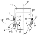
상기 본체 부품들 (11) 의 각각은 축방향 연결 표면들 (AC) 을 포함하고,
적어도 두개의 연속적인 상기 본체 부품들 (11) 사이에는 축방향 연결 조인트 (12) 가 존재하고, 서로를 향해 면하는 상기 본체 부품들 (11) 의 연결 표면들 (AC) 은 몇개의 체결 나사들 (13) 에 의해 서로를 향해 가압되고,
상기 연결 조인트 (12) 는 상기 본체 (3) 의 축방향에 대해 경사진 체결 나사들 (13) 을 포함하는, 충격 유닛의 본체. - 제 1 항에 있어서,
상기 체결 나사들 (13) 은 터닝 헤드들 (15) 을 구비하는 제 1 단부들 및 나사산들 (16) 을 구비하는 제 2 단부 부분들을 포함하고,
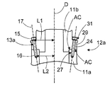
상기 체결 나사들 (13) 은 상기 체결 나사들 (13) 의 종방향 축선 (17) 이 터닝 헤드들 (15) 을 구비하는 대향하는 제 1 단부들과 비교하여 상기 체결 나사들의 나사산형 제 2 단부들 (16) 에서 상기 본체 (3) 의 센터 축선 (D) 에 보다 가깝도록 경사지는, 충격 유닛의 본체. - 제 2 항에 있어서,
상기 연결 조인트 (12) 의 상기 체결 나사들 (13) 의 상기 터닝 헤드들 (15) 은 상기 본체 (3) 의 제 2 단부 (B) 쪽을 향하는, 충격 유닛의 본체. - 제 2 항에 있어서,
상기 연결 조인트 (12) 의 상기 체결 나사들 (13) 의 상기 터닝 헤드들 (15) 은 상기 본체 (3) 의 제 1 단부 (A) 쪽을 향하는, 충격 유닛의 본체. - 제 2 항에 있어서,
상기 연결 조인트 (12) 는 제 1 단부 (A) 쪽을 향하는 적어도 하나의 제 1 체결 나사 (13b) 및 제 2 단부 (B) 쪽을 향하는 적어도 하나의 제 2 체결 나사 (13a) 를 포함하는, 충격 유닛의 본체. - 제 1 항에 있어서,
상기 체결 나사들 (13) 은 상기 연결 조인트 (12) 의 상기 축방향 연결 표면들 (AC) 의 법선 (N) 에 대해 각도 (S) 를 갖고,
상기 체결 나사들 (13) 의 상기 각도 (S) 의 규모는 5 - 15°인, 충격 유닛의 본체. - 제 1 항에 있어서,
상기 체결 나사들 (13) 은 상기 축방향 연결 조인트 (12) 쪽을 향하는 평평한 제 1 지지 표면들 (40) 을 구비하는 터닝 헤드들 (15) 을 포함하고,
상기 축방향 연결 조인트 (12) 는 상기 터닝 헤드들 (15) 의 측에서 지지 플랜지 (29) 를 포함하고, 상기 지지 플랜지 (29) 는 상기 체결 나사들 (15) 이 통과하는 개구들 (24) 를 구비하고 상기 개구들 (24) 에 위치된 몇개의 평평한 제 2 지지 표면들 (31) 을 추가로 포함하고,
상기 평평한 제 2 지지 표면들 (31) 은 상기 체결 나사들 (13) 의 상기 평평한 제 1 지지 표면들 (40) 쪽을 향하고,
상기 평평한 제 1 지지 표면들 (40) 및 상기 평평한 제 2 지지 표면들 (31) 은 경사진 상기 체결 나사들 (13) 의 종방향 축선 (17) 에 대해 수직이고, 그럼으로써 상기 평평한 제 1 지지 표면들 (40) 및 상기 평평한 제 2 지지 표면들 (31) 은 상기 체결 나사들 (13) 이 조여질 때에 서로에 대해 가압되는, 충격 유닛의 본체. - 제 7 항에 있어서,
상기 연결 조인트는 제 1 지지 플랜지 (29) 를 포함하고, 상기 제 1 지지 플랜지 (29) 는 상기 본체 부품 (11) 의 일단부에 위치되고 또 다른 본체 부품쪽을 향하는 환형의 제 1 연결 표면 (AC) 을 구비하고,
상기 제 1 지지 플랜지 (29) 는 상기 제 1 지지 플랜지 (29) 의 대향하는 측에서 환형의 보충 표면 (30) 을 추가로 포함하고,
상기 제 1 지지 플랜지 (29) 의 상기 환형의 보충 표면 (30) 은 상기 본체의 축방향의 센터 라인 (D) 에 수직인 라인에 대해 경사지고,
경사진 상기 환형의 보충 표면 (30) 은 상기 체결 나사들 (13) 의 상기 터닝 헤드들 (15) 을 지지하기 위해 몇개의 평평한 제 2 지지 표면들 (31) 을 구비하는, 충격 유닛의 본체. - 충격 유닛으로서,
본체 (3),
상기 본체 (3) 내측의 충격 디바이스 (ID), 및
상기 충격 유닛에 공구 (2) 를 연결시키기 위해 상기 본체 (3) 의 일단부에 있는 커플링 수단 (19) 을 포함하고,
상기 본체 (3) 는 제 1 항 내지 제 8 항 중 어느 한 항에 따른 것인, 충격 유닛. - 제 9 항에 있어서,
상기 충격 유닛은 파쇄 해머 (1) 로 실시되는, 충격 유닛. - 제 9 항에 있어서,
상기 충격 유닛은 암반 드릴링 기계로 실시되는, 충격 유닛. - 충격 유닛의 본체를 형성하는 방법으로서,
상기 방법은,
적어도 두개의 별개의 세장형의 중공 본체 부품들 (11) 을 형성하는 단계,
상기 본체 부품들 (11) 에 축방향 연결 표면들 (AC) 을 구비하는 단계,
상기 본체 부품들 (11) 을 축방향으로 연속적으로 배열하는 단계, 및
상기 본체 부품들 (11) 의 상기 축방향 연결 표면들 (AC) 을 몇개의 체결 나사들 (13) 에 의해 서로를 향해 가압하는 단계를 포함하고,
상기 본체 부품들 (11) 을 몇개의 경사진 체결 나사들 (13) 에 의해 함께 체결하는 단계를 더 포함하고,
경사진 상기 체결 나사들 (13) 의 방향은 상기 본체 (3) 의 축방향으로부터 벗어난, 충격 유닛의 본체를 형성하는 방법.
Applications Claiming Priority (2)
| Application Number | Priority Date | Filing Date | Title |
|---|---|---|---|
| EP16174979.1 | 2016-06-17 | ||
| EP16174979.1A EP3257634B1 (en) | 2016-06-17 | 2016-06-17 | Arrangement in an impact unit |
Publications (1)
| Publication Number | Publication Date |
|---|---|
| KR20170142877A true KR20170142877A (ko) | 2017-12-28 |
Family
ID=56550011
Family Applications (1)
| Application Number | Title | Priority Date | Filing Date |
|---|---|---|---|
| KR1020170067582A Ceased KR20170142877A (ko) | 2016-06-17 | 2017-05-31 | 충격 유닛에서의 배열체 |
Country Status (4)
| Country | Link |
|---|---|
| US (1) | US20170361445A1 (ko) |
| EP (1) | EP3257634B1 (ko) |
| JP (1) | JP6392415B2 (ko) |
| KR (1) | KR20170142877A (ko) |
Families Citing this family (1)
| Publication number | Priority date | Publication date | Assignee | Title |
|---|---|---|---|---|
| US12546178B2 (en) * | 2024-05-31 | 2026-02-10 | Cameron International Corporation | Split housing connector assembly for a wellhead |
Citations (8)
| Publication number | Priority date | Publication date | Assignee | Title |
|---|---|---|---|---|
| JPH11107851A (ja) * | 1997-10-03 | 1999-04-20 | Honda Motor Co Ltd | 多気筒エンジン |
| KR20010026729A (ko) * | 1999-09-08 | 2001-04-06 | 최성봉 | 경사체결구조를 갖는 삼방향밸브 |
| JP2003227405A (ja) * | 2002-02-04 | 2003-08-15 | Kawasaki Heavy Ind Ltd | 小型エンジン |
| KR20090112287A (ko) * | 2008-04-24 | 2009-10-28 | 문병윤 | 결합핀을 이용한 브레이커의 체결구조 |
| KR20100033797A (ko) * | 2008-09-22 | 2010-03-31 | 코막중공업 주식회사 | 장볼트의 댐핑 및 위치이탈이 방지된 유압브레이커 |
| KR20130098068A (ko) * | 2012-02-27 | 2013-09-04 | 주식회사수산중공업 | 브레이커의 프론트 커버 |
| KR101570335B1 (ko) * | 2014-06-05 | 2015-11-19 | 주식회사수산중공업 | 탄성 지지 구조를 구비한 유압 브레이커 |
| KR101570692B1 (ko) * | 2015-01-07 | 2015-11-20 | 주식회사 에이와이중공업 | 유압 브레이커 |
Family Cites Families (14)
| Publication number | Priority date | Publication date | Assignee | Title |
|---|---|---|---|---|
| DE2207962C3 (de) * | 1972-02-21 | 1980-07-10 | Robert Bosch Gmbh, 7000 Stuttgart | Luftfederhammer |
| DE3010479A1 (de) * | 1980-03-19 | 1981-10-08 | Robert Bosch Gmbh, 7000 Stuttgart | Werkzeugmaschine, insbesondere handwerkzeugmaschine mit einem luftfederschlagwerk |
| JPS6110396U (ja) * | 1984-06-21 | 1986-01-22 | 住友電気工業株式会社 | ケ−シングオ−ガ用カツタ−ビツト |
| JPH081548A (ja) * | 1994-06-14 | 1996-01-09 | Furukawa Co Ltd | ハンドブレーカのハンドル固定機構 |
| JP3847214B2 (ja) * | 2002-06-05 | 2006-11-22 | 富士通株式会社 | 上位ビットの変換誤差補正用レンジを有する補間回路及びそれを利用したa/d変換回路 |
| GB2429991A (en) * | 2005-09-07 | 2007-03-14 | Alan Barrows | Water powered impulsive unit |
| EP1872912B1 (en) * | 2006-07-01 | 2014-03-19 | Black & Decker Inc. | Hammer drill with a beat piece support structure |
| US8146677B2 (en) * | 2008-06-25 | 2012-04-03 | Jae-Mog Kim | Hydraulic breaker assembly |
| JP5121021B2 (ja) * | 2008-09-30 | 2013-01-16 | 株式会社やまびこ | 内燃エンジン付き作業機 |
| FI121220B (fi) * | 2008-11-20 | 2010-08-31 | Sandvik Mining & Constr Oy | Kallioporakone ja aksiaalilaakerimoduuli |
| US20140290973A1 (en) * | 2013-03-27 | 2014-10-02 | Johnson Lin | Pneumatic tool having a rotatable output shaft |
| GB2532934B (en) * | 2014-12-01 | 2019-08-14 | Arrowhead Rockdrill Company Ltd | A method of manufacturing a hydraulic hammer using male and female gauges |
| US9993914B2 (en) * | 2015-08-26 | 2018-06-12 | Caterpillar Inc. | Hammer tool assembly |
| GB2548579B (en) * | 2016-03-21 | 2019-06-26 | Webster Tech Limited | A power tool comprising a tool carrier for mounting an impact tool |
-
2016
- 2016-06-17 EP EP16174979.1A patent/EP3257634B1/en not_active Not-in-force
-
2017
- 2017-05-31 KR KR1020170067582A patent/KR20170142877A/ko not_active Ceased
- 2017-06-16 US US15/625,134 patent/US20170361445A1/en not_active Abandoned
- 2017-06-16 JP JP2017118257A patent/JP6392415B2/ja not_active Expired - Fee Related
Patent Citations (8)
| Publication number | Priority date | Publication date | Assignee | Title |
|---|---|---|---|---|
| JPH11107851A (ja) * | 1997-10-03 | 1999-04-20 | Honda Motor Co Ltd | 多気筒エンジン |
| KR20010026729A (ko) * | 1999-09-08 | 2001-04-06 | 최성봉 | 경사체결구조를 갖는 삼방향밸브 |
| JP2003227405A (ja) * | 2002-02-04 | 2003-08-15 | Kawasaki Heavy Ind Ltd | 小型エンジン |
| KR20090112287A (ko) * | 2008-04-24 | 2009-10-28 | 문병윤 | 결합핀을 이용한 브레이커의 체결구조 |
| KR20100033797A (ko) * | 2008-09-22 | 2010-03-31 | 코막중공업 주식회사 | 장볼트의 댐핑 및 위치이탈이 방지된 유압브레이커 |
| KR20130098068A (ko) * | 2012-02-27 | 2013-09-04 | 주식회사수산중공업 | 브레이커의 프론트 커버 |
| KR101570335B1 (ko) * | 2014-06-05 | 2015-11-19 | 주식회사수산중공업 | 탄성 지지 구조를 구비한 유압 브레이커 |
| KR101570692B1 (ko) * | 2015-01-07 | 2015-11-20 | 주식회사 에이와이중공업 | 유압 브레이커 |
Also Published As
| Publication number | Publication date |
|---|---|
| US20170361445A1 (en) | 2017-12-21 |
| JP2018020428A (ja) | 2018-02-08 |
| EP3257634A1 (en) | 2017-12-20 |
| JP6392415B2 (ja) | 2018-09-19 |
| EP3257634B1 (en) | 2019-02-27 |
Similar Documents
| Publication | Publication Date | Title |
|---|---|---|
| KR101379573B1 (ko) | 파쇄 장치 공구의 베어링 | |
| US6938961B2 (en) | Apparatus for breaking up solid objects | |
| EP0883733B2 (en) | Shank adapter | |
| US20100025114A1 (en) | PCD Percussion Drill Bit | |
| JP5777819B2 (ja) | 破砕ハンマの工具、破砕ハンマおよびその使用 | |
| US20090184564A1 (en) | Pcd percussion drill bit | |
| KR20210102876A (ko) | 타격식 드릴링용 암석 드릴 비트 | |
| KR20170142877A (ko) | 충격 유닛에서의 배열체 | |
| US7055633B2 (en) | Concrete drill | |
| EP4047174B1 (en) | Flushing element, rock drilling machine and method | |
| FI112613B (fi) | Hydraulinen murskausvasara | |
| US10384336B2 (en) | Hydraulic hammer assembly | |
| KR102209256B1 (ko) | 조합형 드릴링 해머 및 그 제작방법 | |
| US9453372B2 (en) | Drill with integrally formed bent sub and sonde housing | |
| KR100908619B1 (ko) | 무진동 암반절개장치 | |
| EP0255536A1 (en) | Drill tool | |
| KR102229577B1 (ko) | 다중체결식 드릴링 해머 및 그 제작방법 | |
| AU2020200965B2 (en) | Ground drilling device, method for making a ground drilling device, method for maintaining a ground drilling device, and use of a ground drilling device | |
| CN222746030U (zh) | 一种冲击器 | |
| US10377029B2 (en) | Hammer sideplate tightening mechanism | |
| US9937613B2 (en) | Striker member, and a drilling machine comprising a striker member | |
| EP4047175B1 (en) | Shank adapter, rock drilling machine and method | |
| CN121205518A (zh) | 一种冲击辅助破岩内凹型pdc钻头 | |
| AU2011200852A1 (en) | Improved Rock Drill | |
| WO2012052597A1 (en) | Method in earth drill bit arrangement assembly and a bit arrangement |
Legal Events
| Date | Code | Title | Description |
|---|---|---|---|
| A201 | Request for examination | ||
| PA0109 | Patent application |
Patent event code: PA01091R01D Comment text: Patent Application Patent event date: 20170531 |
|
| PA0201 | Request for examination | ||
| PG1501 | Laying open of application | ||
| E902 | Notification of reason for refusal | ||
| PE0902 | Notice of grounds for rejection |
Comment text: Notification of reason for refusal Patent event date: 20180412 Patent event code: PE09021S01D |
|
| E601 | Decision to refuse application | ||
| PE0601 | Decision on rejection of patent |
Patent event date: 20180619 Comment text: Decision to Refuse Application Patent event code: PE06012S01D Patent event date: 20180412 Comment text: Notification of reason for refusal Patent event code: PE06011S01I |