KR20200060740A - 차량 제어 장치용 다중 라인 공급 유닛 - Google Patents
차량 제어 장치용 다중 라인 공급 유닛 Download PDFInfo
- Publication number
- KR20200060740A KR20200060740A KR1020207011754A KR20207011754A KR20200060740A KR 20200060740 A KR20200060740 A KR 20200060740A KR 1020207011754 A KR1020207011754 A KR 1020207011754A KR 20207011754 A KR20207011754 A KR 20207011754A KR 20200060740 A KR20200060740 A KR 20200060740A
- Authority
- KR
- South Korea
- Prior art keywords
- line
- supply
- svs1
- svs2
- voltage
- Prior art date
- Legal status (The legal status is an assumption and is not a legal conclusion. Google has not performed a legal analysis and makes no representation as to the accuracy of the status listed.)
- Granted
Links
Images




Classifications
-
- H—ELECTRICITY
- H02—GENERATION; CONVERSION OR DISTRIBUTION OF ELECTRIC POWER
- H02H—EMERGENCY PROTECTIVE CIRCUIT ARRANGEMENTS
- H02H7/00—Emergency protective circuit arrangements specially adapted for specific types of electric machines or apparatus or for sectionalised protection of cable or line systems, and effecting automatic switching in the event of an undesired change from normal working conditions
- H02H7/20—Emergency protective circuit arrangements specially adapted for specific types of electric machines or apparatus or for sectionalised protection of cable or line systems, and effecting automatic switching in the event of an undesired change from normal working conditions for electronic equipment
-
- B—PERFORMING OPERATIONS; TRANSPORTING
- B60—VEHICLES IN GENERAL
- B60R—VEHICLES, VEHICLE FITTINGS, OR VEHICLE PARTS, NOT OTHERWISE PROVIDED FOR
- B60R16/00—Electric or fluid circuits specially adapted for vehicles and not otherwise provided for; Arrangement of elements of electric or fluid circuits specially adapted for vehicles and not otherwise provided for
- B60R16/02—Electric or fluid circuits specially adapted for vehicles and not otherwise provided for; Arrangement of elements of electric or fluid circuits specially adapted for vehicles and not otherwise provided for electric constitutive elements
- B60R16/03—Electric or fluid circuits specially adapted for vehicles and not otherwise provided for; Arrangement of elements of electric or fluid circuits specially adapted for vehicles and not otherwise provided for electric constitutive elements for supply of electrical power to vehicle subsystems or for
-
- G—PHYSICS
- G05—CONTROLLING; REGULATING
- G05B—CONTROL OR REGULATING SYSTEMS IN GENERAL; FUNCTIONAL ELEMENTS OF SUCH SYSTEMS; MONITORING OR TESTING ARRANGEMENTS FOR SUCH SYSTEMS OR ELEMENTS
- G05B19/00—Program-control systems
- G05B19/02—Program-control systems electric
- G05B19/04—Program control other than numerical control, i.e. in sequence controllers or logic controllers
- G05B19/042—Program control other than numerical control, i.e. in sequence controllers or logic controllers using digital processors
-
- H—ELECTRICITY
- H02—GENERATION; CONVERSION OR DISTRIBUTION OF ELECTRIC POWER
- H02H—EMERGENCY PROTECTIVE CIRCUIT ARRANGEMENTS
- H02H1/00—Details of emergency protective circuit arrangements
- H02H1/06—Arrangements for supplying operative power
-
- H—ELECTRICITY
- H02—GENERATION; CONVERSION OR DISTRIBUTION OF ELECTRIC POWER
- H02H—EMERGENCY PROTECTIVE CIRCUIT ARRANGEMENTS
- H02H11/00—Emergency protective circuit arrangements for preventing the switching-on in case an undesired electric working condition might result
- H02H11/002—Emergency protective circuit arrangements for preventing the switching-on in case an undesired electric working condition might result in case of inverted polarity or connection; with switching for obtaining correct connection
-
- H—ELECTRICITY
- H02—GENERATION; CONVERSION OR DISTRIBUTION OF ELECTRIC POWER
- H02H—EMERGENCY PROTECTIVE CIRCUIT ARRANGEMENTS
- H02H11/00—Emergency protective circuit arrangements for preventing the switching-on in case an undesired electric working condition might result
- H02H11/002—Emergency protective circuit arrangements for preventing the switching-on in case an undesired electric working condition might result in case of inverted polarity or connection; with switching for obtaining correct connection
- H02H11/003—Emergency protective circuit arrangements for preventing the switching-on in case an undesired electric working condition might result in case of inverted polarity or connection; with switching for obtaining correct connection using a field effect transistor as protecting element in one of the supply lines
-
- H—ELECTRICITY
- H02—GENERATION; CONVERSION OR DISTRIBUTION OF ELECTRIC POWER
- H02H—EMERGENCY PROTECTIVE CIRCUIT ARRANGEMENTS
- H02H3/00—Emergency protective circuit arrangements for automatic disconnection directly responsive to an undesired change from normal electric working condition with or without subsequent reconnection ; integrated protection
- H02H3/20—Emergency protective circuit arrangements for automatic disconnection directly responsive to an undesired change from normal electric working condition with or without subsequent reconnection ; integrated protection responsive to excess voltage
-
- H—ELECTRICITY
- H02—GENERATION; CONVERSION OR DISTRIBUTION OF ELECTRIC POWER
- H02H—EMERGENCY PROTECTIVE CIRCUIT ARRANGEMENTS
- H02H7/00—Emergency protective circuit arrangements specially adapted for specific types of electric machines or apparatus or for sectionalised protection of cable or line systems, and effecting automatic switching in the event of an undesired change from normal working conditions
- H02H7/26—Sectionalised protection of cable or line systems, e.g. for disconnecting a section on which a short-circuit, earth fault, or arc discharge has occured
-
- H—ELECTRICITY
- H02—GENERATION; CONVERSION OR DISTRIBUTION OF ELECTRIC POWER
- H02H—EMERGENCY PROTECTIVE CIRCUIT ARRANGEMENTS
- H02H7/00—Emergency protective circuit arrangements specially adapted for specific types of electric machines or apparatus or for sectionalised protection of cable or line systems, and effecting automatic switching in the event of an undesired change from normal working conditions
- H02H7/26—Sectionalised protection of cable or line systems, e.g. for disconnecting a section on which a short-circuit, earth fault, or arc discharge has occured
- H02H7/268—Sectionalised protection of cable or line systems, e.g. for disconnecting a section on which a short-circuit, earth fault, or arc discharge has occured for DC systems
-
- H—ELECTRICITY
- H02—GENERATION; CONVERSION OR DISTRIBUTION OF ELECTRIC POWER
- H02J—ELECTRIC POWER NETWORKS; CIRCUIT ARRANGEMENTS OR SYSTEMS FOR SUPPLYING OR DISTRIBUTING ELECTRIC POWER; SYSTEMS FOR STORING ELECTRIC ENERGY
- H02J1/00—Circuit arrangements for DC mains or DC distribution networks
- H02J1/10—Parallel operation of DC sources
-
- H—ELECTRICITY
- H02—GENERATION; CONVERSION OR DISTRIBUTION OF ELECTRIC POWER
- H02J—ELECTRIC POWER NETWORKS; CIRCUIT ARRANGEMENTS OR SYSTEMS FOR SUPPLYING OR DISTRIBUTING ELECTRIC POWER; SYSTEMS FOR STORING ELECTRIC ENERGY
- H02J1/00—Circuit arrangements for DC mains or DC distribution networks
- H02J1/10—Parallel operation of DC sources
- H02J1/108—Parallel operation of DC sources having arrangements for blocking reverse current flow, e.g. using diodes
-
- H—ELECTRICITY
- H02—GENERATION; CONVERSION OR DISTRIBUTION OF ELECTRIC POWER
- H02J—ELECTRIC POWER NETWORKS; CIRCUIT ARRANGEMENTS OR SYSTEMS FOR SUPPLYING OR DISTRIBUTING ELECTRIC POWER; SYSTEMS FOR STORING ELECTRIC ENERGY
- H02J3/00—Circuit arrangements for AC mains or AC distribution networks
- H02J3/38—Arrangements for feeding a single network from two or more generators or sources in parallel; Arrangements for feeding already energised networks from additional generators or sources in parallel
-
- G—PHYSICS
- G05—CONTROLLING; REGULATING
- G05B—CONTROL OR REGULATING SYSTEMS IN GENERAL; FUNCTIONAL ELEMENTS OF SUCH SYSTEMS; MONITORING OR TESTING ARRANGEMENTS FOR SUCH SYSTEMS OR ELEMENTS
- G05B2219/00—Program-control systems
- G05B2219/20—Pc systems
- G05B2219/26—Pc applications
- G05B2219/2637—Vehicle, car, auto, wheelchair
-
- H—ELECTRICITY
- H02—GENERATION; CONVERSION OR DISTRIBUTION OF ELECTRIC POWER
- H02J—ELECTRIC POWER NETWORKS; CIRCUIT ARRANGEMENTS OR SYSTEMS FOR SUPPLYING OR DISTRIBUTING ELECTRIC POWER; SYSTEMS FOR STORING ELECTRIC ENERGY
- H02J2105/00—Networks for supplying or distributing electric power characterised by their spatial reach or by the load
- H02J2105/30—Networks for supplying or distributing electric power characterised by their spatial reach or by the load the load networks being external to vehicles, i.e. exchanging power with vehicles
-
- H—ELECTRICITY
- H02—GENERATION; CONVERSION OR DISTRIBUTION OF ELECTRIC POWER
- H02J—ELECTRIC POWER NETWORKS; CIRCUIT ARRANGEMENTS OR SYSTEMS FOR SUPPLYING OR DISTRIBUTING ELECTRIC POWER; SYSTEMS FOR STORING ELECTRIC ENERGY
- H02J2105/00—Networks for supplying or distributing electric power characterised by their spatial reach or by the load
- H02J2105/30—Networks for supplying or distributing electric power characterised by their spatial reach or by the load the load networks being external to vehicles, i.e. exchanging power with vehicles
- H02J2105/33—Networks for supplying or distributing electric power characterised by their spatial reach or by the load the load networks being external to vehicles, i.e. exchanging power with vehicles exchanging power with road vehicles
-
- H02J2310/46—
Landscapes
- Engineering & Computer Science (AREA)
- Power Engineering (AREA)
- Physics & Mathematics (AREA)
- General Physics & Mathematics (AREA)
- Automation & Control Theory (AREA)
- Mechanical Engineering (AREA)
- Testing Of Short-Circuits, Discontinuities, Leakage, Or Incorrect Line Connections (AREA)
- Charge And Discharge Circuits For Batteries Or The Like (AREA)
- Electronic Switches (AREA)
- Direct Current Feeding And Distribution (AREA)
- Emergency Protection Circuit Devices (AREA)
- Dc-Dc Converters (AREA)
Abstract
Description
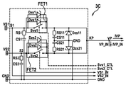
도 2는 보호 장치의 제1 실시예를 포함하는, 차량 제어 장치를 위한 본 발명에 따른 다중 라인 공급 유닛의 제2 실시예의 개략적 회로도이다.
도 3은 하나의 에너지원과 연결되어 있는, 도 1 및 2에서의 본 발명에 따른 다중 라인 공급 유닛들을 위한 보호 장치의 제2 실시예의 개략적 회로도이다.
도 4는 2개의 에너지원과 연결되어 있는 도 3에서의 보호 장치의 개략적 회로도이다.
도 5는 도 1 및 2의 본 발명에 따른 다중 라인 공급 유닛들을 위한 보호 장치의 제3 실시예의 개략적 회로도이다.
도 6은 보호 장치의 제4 실시예를 포함하는, 차량 제어 장치를 위한 본 발명에 따른 다중 라인 공급 유닛의 제3 실시예의 개략적 회로도이다.
도 7은 도 6에서의 차량 제어 장치를 위한 본 발명에 따른 다중 라인 공급 유닛의 평가 및 제어 유닛을 위한 하드웨어 제어 유닛의 일 실시예의 개략적 회로도이다.
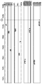
도 8은 도 3에서의 보호 장치를 포함하는, 도 1에서의 차량 제어 장치를 위한 본 발명에 따른 다중 라인 공급 유닛의 정규 작동 동안 전압의 특성곡선 그래프이다.
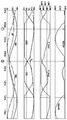
도 9는, 도 4에서의 보호 장치를 포함하는, 도 1 및 도 2에서의 차량 제어 장치를 위한 본 발명에 따른 다중 라인 공급 유닛의 다양한 변수들의 특성곡선 그래프이며, 다중 라인 공급 장치는 상이한 직류 성분들을 보유하고 1kHz 사인파 간섭 전압에 의해 간섭을 받는다.
도 10은 도 4에서의 보호 장치를 포함하는, 도 1 및 2에서의 차량 제어 장치를 위한 본 발명에 따른 다중 라인 공급 유닛의 다양한 변수들의 특성곡선 그래프이며, 다중 라인 공급 장치는 상이한 직류 성분들을 갖는다.


Claims (25)
- 각각 입력단에서 하나 이상의 차량 전압원(B, B1, B2)과 연결되고, 출력단에서는 공통 노드(KP)에서 합쳐지는 2개 이상의 공급 라인(S1, S2)과; 상기 2개 이상의 공급 라인(S1, S2) 내에, 전도 방향으로 하나 이상의 차량 전압원(B, B1, B2)과 노드(KP) 사이에서 2개 이상의 공급 라인(S1, S2)에 루프-인되는 하나 이상의 제1 보호 다이오드(Dvs1, Dvs2)를 각각 포함하는 보호 장치(3A, 3B, 3C, 3D);를 구비한, 차량 제어 장치(2)를 위한 다중 라인 공급 유닛(1A, 1B, 1C)에 있어서,
2개 이상의 공급 라인(S1, S2) 내에 하나 이상의 보호 다이오드(Dvs1, Dvs2)에 대해 병렬로 각각 하나 이상의 스위칭 소자(Svs1, Svs2)가 루프-인되고, 평가 및 제어 유닛(10A, 10B, 10C)이 2개 이상의 공급 라인(S1, S2)의 입력단들에서는 각각 라인 전압(VS1, VS2)을, 그리고 공통 노드(KP)에서는 역극성 보호된 공급 전압(VP)을 검출하여 평가하며, 상기 평가에 기초하여 상응하는 구동 신호들(Svs1_CTL, Svs2_CTL)을 통해 2개 이상의 공급 라인(S1, S2) 내의 스위칭 소자들(Svs1, Svs2)을 구동하는 것을 특징으로 하는, 차량 제어 장치용 다중 라인 공급 유닛(1A, 1B, 1C). - 제1항에 있어서, 평가 및 제어 유닛(10A, 10B, 10C)은 개별 라인 전압들(VS1, VS2)을 서로, 그리고/또는 역극성 보호된 공급 전압(VP)과 비교하고, 이 비교에 따라 하드웨어 제어 유닛(12A, 12B, 12C)을 통해 하나 이상의 스위칭 소자(Svs1, Svs2)를 위한 구동 신호들(Svs1_CTL, Svs2_CTL)을 생성하는 것을 특징으로 하는, 차량 제어 장치용 다중 라인 공급 유닛(1A, 1B, 1C).
- 제2항에 있어서, 평가 및 제어 유닛(10A, 10B, 10C)은, 상응하는 라인 전압(VS1, VS2)과 공통 노드(KP)에서의 역극성 보호된 공급 전압(VP) 간의 차가 기설정 제1 임계값을 상회하는 경우, 하드웨어 제어 유닛(12A, 12B, 12C)에 의해 생성된 구동 신호들(Svs1_CTL, Svs2_CTL)을 통해 하나 이상의 스위칭 소자(Svs1, Svs2)를 폐쇄하는 것을 특징으로 하는, 차량 제어 장치용 다중 라인 공급 유닛(1A, 1B, 1C).
- 제2항 또는 제3항에 있어서, 평가 및 제어 유닛(10A, 10B, 10C)은, 상응하는 라인 전압(VS1, VS2)과 공통 노드(KP) 상에서 역극성 보호된 공급 전압(VP) 간의 차가 기설정 제2 임계값을 하회하는 경우, 하드웨어 제어 유닛(12A, 12B, 12C)에 의해 생성되는 구동 신호들(Svs1_CTL, Svs2_CTL)을 통해 하나 이상의 스위칭 소자(Svs1, Svs2)를 개방하는 것을 특징으로 하는, 차량 제어 장치용 다중 라인 공급 유닛(1A, 1B, 1C).
- 제4항에 있어서, 제1 임계값과 제2 임계값 간의 차는 하드웨어 제어 유닛(12A, 12B, 12C) 내의 가변 저항(Rhys)을 통해 조정될 수 있는 것을 특징으로 하는, 차량 제어 장치용 다중 라인 공급 유닛(1A, 1B, 1C).
- 제1항 내지 제5항 중 어느 한 항에 있어서, 평가 및 제어 유닛(10A, 10B, 10C)은, 기설정 조건들에 따라서 2개 이상의 공급 라인(S1, S2)을 개별적으로 검사하는 컴퓨터 유닛(14A, 14B, 14C)을 포함하며, 컴퓨터 유닛(14A, 14B, 14C)은 2개 이상의 공급 라인(S1, S2)의 검사를 위해 적어도 하나의 제어 신호(STR1_CTL, STR2_CTL)를 생성하여 하드웨어 제어 유닛(12A, 12B, 12C)으로 송출하며, 상기 하드웨어 제어 유닛은 적어도 하나의 제어 신호(STR1_CTL, STR2_CTL)에 반응하여 하나 이상의 스위칭 소자(Svs1, Svs2)를 위한 상응하는 구동 신호들(Svs1_CTL, Svs2_CTL)을 생성하여 송출하는 것을 특징으로 하는, 차량 제어 장치용 다중 라인 공급 유닛(1A, 1B, 1C).
- 제6항에 있어서, 컴퓨터 유닛(14A, 14B, 14C)은, 상기 컴퓨터 유닛(14A, 14B, 14C)이 2개 이상의 공급 라인(S1, S2) 내 라인 단선 및/또는 문제 및/또는 품질 저하를 검출할 경우, 경고 메시지를 생성하고, 그리고/또는 오류 저장을 수행하며, 음향 및/또는 광학 송출 유닛을 통해, 그리고/또는 진단 인터페이스를 통해 송출하는 것을 특징으로 하는, 차량 제어 장치용 다중 라인 공급 유닛(1A, 1B, 1C).
- 제1항 내지 제7항 중 어느 한 항에 있어서, 2개 이상의 공급 라인(S1, S2) 내에서 각각 하나의 전계효과 트랜지스터(FET1, FET2)가 하나 이상의 제1 보호 다이오드(Dvs1, Dvs2) 및 하나 이상의 스위칭 소자(Svs1, Svs2)를 형성하는 것을 특징으로 하는, 차량 제어 장치용 다중 라인 공급 유닛(1A, 1B, 1C).
- 제1항 내지 제8항 중 어느 한 항에 있어서, 하나 이상의 제2 보호 다이오드(Dzs1, Dzs2)는 2개 이상의 공급 라인(S1, S2) 내에서 하나 이상의 제1 보호 다이오드(Dvs1, Dvs2)에 대해, 그리고 하나 이상의 스위칭 소자(Svs1, Svs2)에 대해 각각 병렬로 배치되며, 하나 이상의 스위칭 소자(Svs1, Svs2)의 펄스 부하를 감소시키기에 적합한 것을 특징으로 하는, 차량 제어 장치용 다중 라인 공급 유닛(1A, 1B, 1C).
- 제1항 내지 제9항 중 어느 한 항에 있어서, 2개 이상의 공급 라인(S1, S2)의 출력단들은 각각 개별적으로 공통 노드(KP)의 상류에서, 또는 함께 공통 노드(KP)에서, 2개 이상의 공급 라인(S1, S2)의 양의 펄스 부하를 감소시키기에 적합한 하나 이상의 제3 보호 다이오드(Dzp, Dzs11, Dzs21)를 통해 접지(GND)와 연결되며, 하나 이상의 제3 보호 다이오드(Dzp, Dzs11, Dzs21)는, 공통 노드(KP)에서 발생하는 음의 전압을 기설정 가능한 값으로 제한하고, 결함이 있는 라인 스위치(Svs1, Svs2)의 경우 역극성 시 전기적 차량 안전장치를 트리거링하는 것을 특징으로 하는, 차량 제어 장치용 다중 라인 공급 유닛(1A, 1B, 1C).
- 제1항 내지 제10항 중 어느 한 항에 있어서, 2개 이상의 공급 라인(S1, S2)의 입력단들은, 각각 옴 저항(Rs1, Rs2)과 커패시터(Cs1, Cs2)를 포함하는 하나 이상의 RC 소자를 통해, 접지(GND)와 연결되어 감쇠되는 것을 특징으로 하는, 차량 제어 장치용 다중 라인 공급 유닛(1A, 1B, 1C).
- 제1항 내지 제11항 중 어느 한 항에 있어서, 2개 이상의 공급 라인(S1, S2)의 출력단들은, 각각 개별적으로 공통 노드(KP)의 상류에서, 또는 함께 공통 노드(KP)에서, 옴 저항(RP, Rs11, Rs21)과 커패시터(CP, Cs11, Cs21)를 포함하는 적어도 하나의 RC 소자를 통해, 접지(GND)와 연결되어 감쇠되는 것을 특징으로 하는, 차량 제어 장치용 다중 라인 공급 유닛(1A, 1B, 1C).
- 제1항 내지 제12항 중 어느 한 항에 있어서, 공통 노드(KP)는 패시브 필터(20)를 통해 제어 장치(2)와 연결될 수 있는 것을 특징으로 하는, 차량 제어 장치용 다중 라인 공급 유닛(1A, 1B, 1C).
- 제13항에 있어서, 패시브 필터(20)는, 단시간 전압 강하를 보상하기에 적합한 에너지 예비 장치(CμCT)를 포함하는 것을 특징으로 하는, 차량 제어 장치용 다중 라인 공급 유닛(1A, 1B, 1C).
- 제13항 또는 제14항에 있어서, 패시브 필터(20)는 다중 라인 T 필터(20C)로서 형성되고, 각각 하나의 제1 필터 인덕터(LT1, LT2)는 스위칭 소자(Svs1, Svs2)와 공통 노드(KP) 사이에서 2개 이상의 공급 라인(S1, S2)에 루프-인되며, 공통의 제2 필터 인덕터(LT)는 공통 노드(KP)와 필터 출력단 사이에 루프-인되는 것을 특징으로 하는, 차량 제어 장치용 다중 라인 공급 유닛(1A, 1B, 1C).
- 제1항 내지 제15항 중 어느 한 항에 따른 다중 라인 공급 유닛(1A, 1B, 1C)의 작동 방법에 있어서,
2개 이상의 공급 라인(S1, S2)의 입력단들에서 각각 라인 전압(VS1, VS2)이, 그리고 공통 노드(KP)에서는 역극성 보호된 공급 전압(VP)이 검출되어 평가되며, 2개 이상의 공급 라인(S1, S2) 내의 스위칭 소자들(Svs1, Svs2)은 평가에 따라서 상응하는 구동 신호들(Svs1_CTL, Svs2_CTL)을 통해 구동되는 것을 특징으로 하는, 다중 라인 공급 유닛용 작동 방법. - 제16항에 있어서, 개별 라인 전압들(VS1, VS2)은 서로, 그리고/또는 역극성 보호된 공급 전압(VP)과 비교되며, 이 비교에 따라서 하나 이상의 스위칭 소자(Svs1, Svs2)를 위한 구동 신호들(Svs1_CTL, Svs2_CTL)이 하드웨어 제어 유닛(12A, 12B, 12C)을 통해 생성되는 것을 특징으로 하는, 다중 라인 공급 유닛용 작동 방법.
- 제16항 또는 제17항에 있어서, 2개 이상의 공급 라인(S1, S2)은 작동 동안 기설정 조건들에 따라서 개별적으로 검사되는 것을 특징으로 하는, 다중 라인 공급 유닛용 작동 방법.
- 제18항에 있어서, 2개 이상의 공급 라인(S1, S2)은, 기설정 시간 간격들로, 그리고/또는 라인 전압들(VS1, VS2) 간의 전압차가 기설정 절댓값을 상회하는 경우, 개별적으로 검사되는 것을 특징으로 하는, 다중 라인 공급 유닛용 작동 방법.
- 제18항 또는 제19항에 있어서, 2개 이상의 공급 라인(S1, S2)의 제1 검사 시, 검사할 공급 라인(S1, S2)의 하나 이상의 스위칭 소자(Svs1, Svs2)는 개방되며, 상응하는 라인 전압(VS1, VS2) 및 공통 노드(KP)에서의 역극성 보호된 공급 전압(VP)의 반응들이 검출되어 평가되는 것을 특징으로 하는, 다중 라인 공급 유닛용 작동 방법.
- 제20항에 있어서, 스위칭 소자(Svs1, Svs2)의 개방 시 상응하는 라인 전압(VS1, VS2)이 기설정 최소 한계값을 하회하는 경우, 검사할 공급 라인(S1, S2) 내 라인 단선이 검출되는 것을 특징으로 하는, 다중 라인 공급 유닛용 작동 방법.
- 제18항 내지 제21항 중 어느 한 항에 있어서, 2개 이상의 공급 라인(S1, S2)의 제2 검사 시, 검사할 공급 라인(S1, S2)의 상응하는 스위칭 소자(Svs1, Svs2)만 폐쇄되고, 타측 공급 라인들(S1, S2)의 스위칭 소자들(Svs1, Svs2)은 개방되며, 검사할 공급 라인(S1, S2)의 부하 인가 상태에서, 상응하는 라인 전압(VS1, VS2)의 반응이 검출되어 평가되는 것을 특징으로 하는, 다중 라인 공급 유닛용 작동 방법.
- 제22항에 있어서, 스위칭 소자(Svs1, Svs2)의 폐쇄 시 상응하는 라인 전압(VS1, VS2)이 기설정 부하 한계값을 하회하는 경우, 부하가 인가된 검사할 공급 라인(S1, S2) 내의 문제가 검출되는 것을 특징으로 하는, 다중 라인 공급 유닛용 작동 방법.
- 제18항 내지 제23항 중 어느 한 항에 있어서, 개별 라인 전압들(VS1, VS2)은 서로, 그리고 각각 연결된 차량 전압원(B1, B2)의 차량 전압(UB1, UB2)과 비교되며, 상기 비교를 기반으로, 상응하는 공급 라인(S1, S2)의 내부 저항(Ri1, Ri2)의 크기가 추론되는 것을 특징으로 하는, 다중 라인 공급 유닛용 작동 방법.
- 제18항 내지 제24항 중 어느 한 항에 있어서, 2개 이상의 공급 라인(S1, S2) 내 라인 단선 및/또는 문제 및/또는 품질 저하가 검출될 경우, 경고 메시지가 생성되고, 그리고/또는 오류 저장이 수행되며, 음향 및/또는 광학 송출 유닛을 통해 그리고/또는 진단 인터페이스를 통해 송출되고, 이때 품질 저하는, 내부 저항(Ri1, Ri2)이 기설정 한계값을 상회하는 점을 통해 검출되는 것을 특징으로 하는, 다중 라인 공급 유닛용 작동 방법.
Applications Claiming Priority (3)
| Application Number | Priority Date | Filing Date | Title |
|---|---|---|---|
| DE102017217003.4A DE102017217003A1 (de) | 2017-09-26 | 2017-09-26 | Mehrstrangversorgungseinheit für ein Fahrzeugsteuergerät |
| DE102017217003.4 | 2017-09-26 | ||
| PCT/EP2018/072116 WO2019063186A1 (de) | 2017-09-26 | 2018-08-15 | Mehrstrangversorgungseinheit für ein fahrzeugsteuergerät |
Publications (2)
| Publication Number | Publication Date |
|---|---|
| KR20200060740A true KR20200060740A (ko) | 2020-06-01 |
| KR102568231B1 KR102568231B1 (ko) | 2023-08-23 |
Family
ID=63350529
Family Applications (1)
| Application Number | Title | Priority Date | Filing Date |
|---|---|---|---|
| KR1020207011754A Active KR102568231B1 (ko) | 2017-09-26 | 2018-08-15 | 차량 제어 장치용 다중 라인 공급 유닛 |
Country Status (8)
| Country | Link |
|---|---|
| US (1) | US11177655B2 (ko) |
| EP (1) | EP3688854A1 (ko) |
| JP (1) | JP6993514B2 (ko) |
| KR (1) | KR102568231B1 (ko) |
| CN (1) | CN111133650B (ko) |
| DE (1) | DE102017217003A1 (ko) |
| MX (1) | MX2020003025A (ko) |
| WO (1) | WO2019063186A1 (ko) |
Families Citing this family (5)
| Publication number | Priority date | Publication date | Assignee | Title |
|---|---|---|---|---|
| DE102020113629A1 (de) | 2020-05-20 | 2021-11-25 | Bayerische Motoren Werke Aktiengesellschaft | Elektrischer Verbraucher und Verfahren zur Anbindung eines elektrischen Verbrauchers an ein elektrisches Bordnetz |
| DE102020115461A1 (de) * | 2020-06-10 | 2021-12-16 | Auto-Kabel Management Gmbh | Kraftfahrzeugbordnetzschalter, Kraftfahrzeugbordnetz und Verfahren zum Betreiben eines Kraftfahrzeugbordnetzschalters |
| JP7501314B2 (ja) * | 2020-11-06 | 2024-06-18 | 株式会社アイシン | センサモジュール |
| CN114301028B (zh) | 2021-12-29 | 2023-09-29 | 视涯科技股份有限公司 | 一种过流保护电路及显示装置 |
| EP4435991A1 (en) * | 2023-03-21 | 2024-09-25 | Aptiv Technologies AG | Electrical power supply |
Citations (4)
| Publication number | Priority date | Publication date | Assignee | Title |
|---|---|---|---|---|
| JPH09140065A (ja) * | 1995-11-10 | 1997-05-27 | Sony Corp | 並列使用の2次電池装置 |
| US5757099A (en) * | 1996-03-01 | 1998-05-26 | Wisconsin Alumni Research Foundation | Hybrid parallel active/passive filter system with dynamically variable inductance |
| US20060002043A1 (en) * | 2004-04-30 | 2006-01-05 | Disalvo Nicholas L | Overcurrent protection for circuit interrupting devices |
| US20120228943A1 (en) * | 2010-10-15 | 2012-09-13 | Sanyo Electric Co., Ltd. | Electric power supply system |
Family Cites Families (18)
| Publication number | Priority date | Publication date | Assignee | Title |
|---|---|---|---|---|
| JPH03243119A (ja) | 1990-02-19 | 1991-10-30 | Nippon Telegr & Teleph Corp <Ntt> | オア回路 |
| JPH05328606A (ja) | 1992-05-18 | 1993-12-10 | Kokusai Electric Co Ltd | 2重化直流電源回路 |
| JPH0775348A (ja) | 1993-08-31 | 1995-03-17 | Toshiba Corp | 燃料電池装置 |
| JPH09261861A (ja) * | 1996-03-22 | 1997-10-03 | Omron Corp | 逆流防止装置、整流装置および太陽光発電システム |
| JP2001053597A (ja) | 1999-08-06 | 2001-02-23 | Matsushita Electric Works Ltd | 照度センサおよび電子式自動点滅器 |
| JP2007082306A (ja) | 2005-09-13 | 2007-03-29 | Hitachi Ltd | 電源供給装置 |
| FR2910141B1 (fr) * | 2006-12-18 | 2009-02-20 | Agence Spatiale Europeenne | Systeme de generation d'energie electrique avec maximisation de la puissance |
| JP2009077510A (ja) | 2007-09-20 | 2009-04-09 | Hitachi Ltd | 電解コンデンサの充放電回路 |
| JP5130906B2 (ja) | 2007-12-26 | 2013-01-30 | サンケン電気株式会社 | スイッチ装置 |
| JP4573884B2 (ja) | 2008-06-18 | 2010-11-04 | 三菱電機株式会社 | 車載電子制御装置の電源異常検出回路 |
| DE202010018348U1 (de) * | 2010-01-13 | 2015-10-20 | Phoenix Contact Gmbh & Co. Kg | Redundanzmodul mit symmetrischen Strompfaden |
| US8536730B2 (en) * | 2010-07-12 | 2013-09-17 | Hamilton Sundstrand Corporation | Electric power generating and distribution system comprising a decoupling filter and a solid state power controller |
| JP5492849B2 (ja) | 2011-09-20 | 2014-05-14 | 日立オートモティブシステムズ株式会社 | 車載用制御装置 |
| DE102011117178A1 (de) * | 2011-10-28 | 2013-05-02 | Sma Solar Technology Ag | Wechselrichter mit überbrückbarer Rückstromschutzvorrichtung |
| CN102496923B (zh) * | 2011-11-14 | 2016-10-19 | 株洲南车时代电气股份有限公司 | 一种防反接保护的输入电路 |
| DE102012212123B4 (de) * | 2012-07-11 | 2016-05-19 | Continental Automotive Gmbh | Vorrichtung zur Diagnose einer Schaltungsanordnung |
| CN103441486A (zh) * | 2013-08-14 | 2013-12-11 | 上海华兴数字科技有限公司 | 一种大电流电源防反接保护电路 |
| JP6274061B2 (ja) | 2014-09-26 | 2018-02-07 | 株式会社オートネットワーク技術研究所 | 車載機 |
-
2017
- 2017-09-26 DE DE102017217003.4A patent/DE102017217003A1/de active Pending
-
2018
- 2018-08-15 KR KR1020207011754A patent/KR102568231B1/ko active Active
- 2018-08-15 JP JP2020537845A patent/JP6993514B2/ja active Active
- 2018-08-15 US US16/647,190 patent/US11177655B2/en active Active
- 2018-08-15 WO PCT/EP2018/072116 patent/WO2019063186A1/de not_active Ceased
- 2018-08-15 MX MX2020003025A patent/MX2020003025A/es unknown
- 2018-08-15 EP EP18759071.6A patent/EP3688854A1/de active Pending
- 2018-08-15 CN CN201880062687.8A patent/CN111133650B/zh active Active
Patent Citations (4)
| Publication number | Priority date | Publication date | Assignee | Title |
|---|---|---|---|---|
| JPH09140065A (ja) * | 1995-11-10 | 1997-05-27 | Sony Corp | 並列使用の2次電池装置 |
| US5757099A (en) * | 1996-03-01 | 1998-05-26 | Wisconsin Alumni Research Foundation | Hybrid parallel active/passive filter system with dynamically variable inductance |
| US20060002043A1 (en) * | 2004-04-30 | 2006-01-05 | Disalvo Nicholas L | Overcurrent protection for circuit interrupting devices |
| US20120228943A1 (en) * | 2010-10-15 | 2012-09-13 | Sanyo Electric Co., Ltd. | Electric power supply system |
Also Published As
| Publication number | Publication date |
|---|---|
| KR102568231B1 (ko) | 2023-08-23 |
| EP3688854A1 (de) | 2020-08-05 |
| WO2019063186A1 (de) | 2019-04-04 |
| US20210159694A1 (en) | 2021-05-27 |
| DE102017217003A1 (de) | 2019-03-28 |
| CN111133650A (zh) | 2020-05-08 |
| JP2020535785A (ja) | 2020-12-03 |
| US11177655B2 (en) | 2021-11-16 |
| CN111133650B (zh) | 2022-09-27 |
| JP6993514B2 (ja) | 2022-02-15 |
| MX2020003025A (es) | 2020-07-22 |
Similar Documents
| Publication | Publication Date | Title |
|---|---|---|
| KR102568231B1 (ko) | 차량 제어 장치용 다중 라인 공급 유닛 | |
| KR101818017B1 (ko) | 다전압 차량 전기 시스템의 구성요소를 격리시키는 회로 모듈 | |
| US10618479B2 (en) | Controller for a multi-voltage on-board power supply system in a vehicle | |
| US11171481B1 (en) | Dual-supply automotive electrical system with protection of motion control components | |
| US10090666B2 (en) | Circuit architectures for protecting against PoDL wire faults | |
| US20120126782A1 (en) | Low voltage electronic module interface | |
| US10882475B2 (en) | Multi-voltage control device for a motor vehicle, motor vehicle and operating method for the control device | |
| US11124138B2 (en) | Device for supplying power to a control unit and method for monitoring a power supply | |
| KR102522948B1 (ko) | 차량용 안전 유닛을 위한 활성화 전압의 제공을 위한 장치 및 방법, 그리고 안전 장치 | |
| EP4005053B1 (en) | Power supply system with protection against current variations | |
| US20180372807A1 (en) | Bus system and method for diagnosing a short circuit | |
| KR101636291B1 (ko) | 정션박스의 전원 공급 배선 장애 검출 장치 및 그 방법 | |
| WO2019111673A1 (ja) | 信号出力装置 | |
| EP0954079B1 (en) | Bidirectional electronic switch | |
| US7834756B2 (en) | Failure current measurement for electronic control module | |
| US20170310259A1 (en) | Device for controlling a regulator of a motor vehicle alternator, and alternator comprising the corresponding regulator | |
| KR20150023343A (ko) | 승객 보호 수단을 위한 집적 조정기, 특히 전압 조정기 및 제어 장치 | |
| KR102773056B1 (ko) | 모스펫 소자 보호 회로를 구비한 차량 제어 장치 및 그것의 모스펫 소자 보호 방법 | |
| CN116323330B (zh) | 防止由其它安全气囊的引线短路引起的安全气囊不展开的方法 | |
| JP4453616B2 (ja) | 電子制御装置及び通信システム並びにサージ吸収素子の検査方法 | |
| EP3422142B1 (en) | Method for providing electric power to an interface card and safe state controller | |
| JP2022098602A (ja) | 負荷駆動装置 | |
| JP2000354072A (ja) | 2線式線路上の干渉性縦電圧を低減する低減回路を備える回路装置 | |
| JPH04177940A (ja) | 多重伝送における終端回路 |
Legal Events
| Date | Code | Title | Description |
|---|---|---|---|
| PA0105 | International application |
St.27 status event code: A-0-1-A10-A15-nap-PA0105 |
|
| P11-X000 | Amendment of application requested |
St.27 status event code: A-2-2-P10-P11-nap-X000 |
|
| P13-X000 | Application amended |
St.27 status event code: A-2-2-P10-P13-nap-X000 |
|
| PG1501 | Laying open of application |
St.27 status event code: A-1-1-Q10-Q12-nap-PG1501 |
|
| A201 | Request for examination | ||
| PA0201 | Request for examination |
St.27 status event code: A-1-2-D10-D11-exm-PA0201 |
|
| D13-X000 | Search requested |
St.27 status event code: A-1-2-D10-D13-srh-X000 |
|
| D14-X000 | Search report completed |
St.27 status event code: A-1-2-D10-D14-srh-X000 |
|
| E902 | Notification of reason for refusal | ||
| PE0902 | Notice of grounds for rejection |
St.27 status event code: A-1-2-D10-D21-exm-PE0902 |
|
| E13-X000 | Pre-grant limitation requested |
St.27 status event code: A-2-3-E10-E13-lim-X000 |
|
| P11-X000 | Amendment of application requested |
St.27 status event code: A-2-2-P10-P11-nap-X000 |
|
| P13-X000 | Application amended |
St.27 status event code: A-2-2-P10-P13-nap-X000 |
|
| E701 | Decision to grant or registration of patent right | ||
| PE0701 | Decision of registration |
St.27 status event code: A-1-2-D10-D22-exm-PE0701 |
|
| GRNT | Written decision to grant | ||
| PR0701 | Registration of establishment |
St.27 status event code: A-2-4-F10-F11-exm-PR0701 |
|
| PR1002 | Payment of registration fee |
St.27 status event code: A-2-2-U10-U12-oth-PR1002 Fee payment year number: 1 |
|
| PG1601 | Publication of registration |
St.27 status event code: A-4-4-Q10-Q13-nap-PG1601 |
|
| P22-X000 | Classification modified |
St.27 status event code: A-4-4-P10-P22-nap-X000 |