US11511323B2 - Vibration device and optical detection device - Google Patents
Vibration device and optical detection device Download PDFInfo
- Publication number
- US11511323B2 US11511323B2 US16/817,677 US202016817677A US11511323B2 US 11511323 B2 US11511323 B2 US 11511323B2 US 202016817677 A US202016817677 A US 202016817677A US 11511323 B2 US11511323 B2 US 11511323B2
- Authority
- US
- United States
- Prior art keywords
- vibration device
- elastic member
- vibrator
- cylinder
- support body
- Prior art date
- Legal status (The legal status is an assumption and is not a legal conclusion. Google has not performed a legal analysis and makes no representation as to the accuracy of the status listed.)
- Active, expires
Links
Images



Classifications
-
- B—PERFORMING OPERATIONS; TRANSPORTING
- B08—CLEANING
- B08B—CLEANING IN GENERAL; PREVENTION OF FOULING IN GENERAL
- B08B7/00—Cleaning by methods not provided for in a single other subclass or a single group in this subclass
- B08B7/02—Cleaning by methods not provided for in a single other subclass or a single group in this subclass by distortion, beating, or vibration of the surface to be cleaned
-
- B—PERFORMING OPERATIONS; TRANSPORTING
- B06—GENERATING OR TRANSMITTING MECHANICAL VIBRATIONS IN GENERAL
- B06B—METHODS OR APPARATUS FOR GENERATING OR TRANSMITTING MECHANICAL VIBRATIONS OF INFRASONIC, SONIC, OR ULTRASONIC FREQUENCY, e.g. FOR PERFORMING MECHANICAL WORK IN GENERAL
- B06B1/00—Methods or apparatus for generating mechanical vibrations of infrasonic, sonic, or ultrasonic frequency
- B06B1/02—Methods or apparatus for generating mechanical vibrations of infrasonic, sonic, or ultrasonic frequency making use of electrical energy
- B06B1/0207—Driving circuits
-
- B—PERFORMING OPERATIONS; TRANSPORTING
- B06—GENERATING OR TRANSMITTING MECHANICAL VIBRATIONS IN GENERAL
- B06B—METHODS OR APPARATUS FOR GENERATING OR TRANSMITTING MECHANICAL VIBRATIONS OF INFRASONIC, SONIC, OR ULTRASONIC FREQUENCY, e.g. FOR PERFORMING MECHANICAL WORK IN GENERAL
- B06B1/00—Methods or apparatus for generating mechanical vibrations of infrasonic, sonic, or ultrasonic frequency
- B06B1/02—Methods or apparatus for generating mechanical vibrations of infrasonic, sonic, or ultrasonic frequency making use of electrical energy
- B06B1/06—Methods or apparatus for generating mechanical vibrations of infrasonic, sonic, or ultrasonic frequency making use of electrical energy operating with piezoelectric effect or with electrostriction
- B06B1/0644—Methods or apparatus for generating mechanical vibrations of infrasonic, sonic, or ultrasonic frequency making use of electrical energy operating with piezoelectric effect or with electrostriction using a single piezoelectric element
- B06B1/0651—Methods or apparatus for generating mechanical vibrations of infrasonic, sonic, or ultrasonic frequency making use of electrical energy operating with piezoelectric effect or with electrostriction using a single piezoelectric element of circular shape
-
- B—PERFORMING OPERATIONS; TRANSPORTING
- B08—CLEANING
- B08B—CLEANING IN GENERAL; PREVENTION OF FOULING IN GENERAL
- B08B7/00—Cleaning by methods not provided for in a single other subclass or a single group in this subclass
- B08B7/04—Cleaning by methods not provided for in a single other subclass or a single group in this subclass by a combination of operations
-
- G—PHYSICS
- G02—OPTICS
- G02B—OPTICAL ELEMENTS, SYSTEMS OR APPARATUS
- G02B27/00—Optical systems or apparatus not provided for by any of the groups G02B1/00 - G02B26/00, G02B30/00
- G02B27/0006—Optical systems or apparatus not provided for by any of the groups G02B1/00 - G02B26/00, G02B30/00 with means to keep optical surfaces clean, e.g. by preventing or removing dirt, stains, contamination, condensation
-
- G—PHYSICS
- G03—PHOTOGRAPHY; CINEMATOGRAPHY; ANALOGOUS TECHNIQUES USING WAVES OTHER THAN OPTICAL WAVES; ELECTROGRAPHY; HOLOGRAPHY
- G03B—APPARATUS OR ARRANGEMENTS FOR TAKING PHOTOGRAPHS OR FOR PROJECTING OR VIEWING THEM; APPARATUS OR ARRANGEMENTS EMPLOYING ANALOGOUS TECHNIQUES USING WAVES OTHER THAN OPTICAL WAVES; ACCESSORIES THEREFOR
- G03B17/00—Details of cameras or camera bodies; Accessories therefor
-
- G—PHYSICS
- G03—PHOTOGRAPHY; CINEMATOGRAPHY; ANALOGOUS TECHNIQUES USING WAVES OTHER THAN OPTICAL WAVES; ELECTROGRAPHY; HOLOGRAPHY
- G03B—APPARATUS OR ARRANGEMENTS FOR TAKING PHOTOGRAPHS OR FOR PROJECTING OR VIEWING THEM; APPARATUS OR ARRANGEMENTS EMPLOYING ANALOGOUS TECHNIQUES USING WAVES OTHER THAN OPTICAL WAVES; ACCESSORIES THEREFOR
- G03B17/00—Details of cameras or camera bodies; Accessories therefor
- G03B17/02—Bodies
-
- G—PHYSICS
- G03—PHOTOGRAPHY; CINEMATOGRAPHY; ANALOGOUS TECHNIQUES USING WAVES OTHER THAN OPTICAL WAVES; ELECTROGRAPHY; HOLOGRAPHY
- G03B—APPARATUS OR ARRANGEMENTS FOR TAKING PHOTOGRAPHS OR FOR PROJECTING OR VIEWING THEM; APPARATUS OR ARRANGEMENTS EMPLOYING ANALOGOUS TECHNIQUES USING WAVES OTHER THAN OPTICAL WAVES; ACCESSORIES THEREFOR
- G03B17/00—Details of cameras or camera bodies; Accessories therefor
- G03B17/02—Bodies
- G03B17/08—Waterproof bodies or housings
-
- H—ELECTRICITY
- H04—ELECTRIC COMMUNICATION TECHNIQUE
- H04N—PICTORIAL COMMUNICATION, e.g. TELEVISION
- H04N23/00—Cameras or camera modules comprising electronic image sensors; Control thereof
- H04N23/50—Constructional details
- H04N23/52—Elements optimising image sensor operation, e.g. for electromagnetic interference [EMI] protection or temperature control by heat transfer or cooling elements
-
- H04N5/22521—
-
- B—PERFORMING OPERATIONS; TRANSPORTING
- B06—GENERATING OR TRANSMITTING MECHANICAL VIBRATIONS IN GENERAL
- B06B—METHODS OR APPARATUS FOR GENERATING OR TRANSMITTING MECHANICAL VIBRATIONS OF INFRASONIC, SONIC, OR ULTRASONIC FREQUENCY, e.g. FOR PERFORMING MECHANICAL WORK IN GENERAL
- B06B1/00—Methods or apparatus for generating mechanical vibrations of infrasonic, sonic, or ultrasonic frequency
- B06B1/02—Methods or apparatus for generating mechanical vibrations of infrasonic, sonic, or ultrasonic frequency making use of electrical energy
- B06B1/06—Methods or apparatus for generating mechanical vibrations of infrasonic, sonic, or ultrasonic frequency making use of electrical energy operating with piezoelectric effect or with electrostriction
-
- G—PHYSICS
- G03—PHOTOGRAPHY; CINEMATOGRAPHY; ANALOGOUS TECHNIQUES USING WAVES OTHER THAN OPTICAL WAVES; ELECTROGRAPHY; HOLOGRAPHY
- G03B—APPARATUS OR ARRANGEMENTS FOR TAKING PHOTOGRAPHS OR FOR PROJECTING OR VIEWING THEM; APPARATUS OR ARRANGEMENTS EMPLOYING ANALOGOUS TECHNIQUES USING WAVES OTHER THAN OPTICAL WAVES; ACCESSORIES THEREFOR
- G03B2205/00—Adjustment of optical system relative to image or object surface other than for focusing
- G03B2205/0053—Driving means for the movement of one or more optical element
- G03B2205/0061—Driving means for the movement of one or more optical element using piezoelectric actuators
Definitions
- the present invention relates to a vibration device and an optical detection device capable of removing water droplets or the like by mechanical vibration.
- Japanese Unexamined Patent Application Publication No. 2017-170303 discloses a liquid droplet removing device in which a piezoelectric element is attached to a drip-proof cover disposed in front of an imaging element. By vibrating the drip-proof cover, droplets in a field of view of an imaging element are removed.
- the drip-proof cover is held by a support frame.
- the imaging element is disposed in an internal space formed by the drip-proof cover and the support frame.
- the piezoelectric element is directly attached to the drip-proof cover.
- the portion of the drip-proof cover outside the field of view is held by the support frame.
- a stress is applied to the drip-proof cover or the piezoelectric element in a vibrator, and vibration is inhibited.
- Preferred embodiments of the present invention provide vibration devices and optical detection devices that are each capable of reducing or preventing an influence of a stress applied to a vibrator, and that are each capable of effectively vibrating a cover to which water droplets or the like are attached.
- a vibration device includes a vibrator including a cylinder with an opening, a light-transmissive cover directly or indirectly coupled to the cylinder so as to cover the opening of the cylinder, a piezoelectric element to vibrate the light-transmissive cover, and including an opening end portion, an elastic member holding the opening end portion of the vibrator, and a case connected to the elastic member.
- a vibration device includes a vibrator including a cylinder with an opening, a light-transmissive cover directly or indirectly coupled to the cylinder so as to cover the opening of the cylinder, a piezoelectric element to vibrate the light-transmissive cover, and including an opening end portion, and a case provided with a projecting portion holding the opening end portion of the vibrator.
- An optical detection device includes a vibration device according to a preferred embodiment of the present invention, and an optical detection element disposed so that a detection region is included in the light-transmissive cover.
- FIG. 1 is a schematic elevation sectional view of a vibration device according to a first preferred embodiment of the present invention.
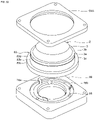
- FIG. 2 is an exploded perspective view of the vibration device according to the first preferred embodiment of the present invention.
- FIG. 3 is a diagram illustrating thermal stress distribution at about ⁇ 55° C. with reference to about 140° C. standards in a first comparative example.
- FIG. 4 is a diagram illustrating thermal stress distribution at about ⁇ 55° C. with reference to about 140° C. standards in the first preferred embodiment of the present invention.
- FIG. 5 is a schematic elevation sectional view of a vibration device according to a modified example of the first preferred embodiment of the present invention.
- FIG. 6 is a schematic elevation sectional view of a vibration device according to a second preferred embodiment of the present invention.
- FIG. 7 is an exploded perspective view of the vibration device according to the second preferred embodiment of the present invention.
- FIG. 8 is a diagram illustrating thermal stress distribution at about ⁇ 55° C. with reference to about 140° C. standards in the second preferred embodiment of the present invention.
- FIG. 9 is a schematic elevation sectional view of a vibration device according to a third preferred embodiment of the present invention.
- FIG. 10 is an exploded perspective view of the vibration device according to the third preferred embodiment of the present invention, from which a side wall portion of a case member is omitted.
- FIG. 11 is an enlarged view of FIG. 9 .
- FIG. 12 is a diagram illustrating a rate of change in a displacement amount in each of the vibration device according to the third preferred embodiment of the present invention and a vibration device according to a second comparative example, with reference to a normal temperature.
- FIG. 13 is a schematic elevation sectional view illustrating a vicinity of an elastic member in a vibration device according to a first modified example of the third preferred embodiment of the present invention.
- FIG. 14 is a schematic elevation sectional view illustrating a vicinity of an elastic member in a vibration device according to a second modified example of the third preferred embodiment of the present invention.
- FIG. 15 is a schematic elevation sectional view illustrating a vicinity of an elastic member in a vibration device according to a third modified example of the third preferred embodiment of the present invention.
- FIG. 16 is a schematic elevation sectional view illustrating a vicinity of an elastic member in a vibration device according to a fourth modified example of the third preferred embodiment of the present invention.
- FIG. 17 is a schematic elevation sectional view of a vibration device according to a fourth preferred embodiment of the present invention.
- FIG. 18 is an enlarged view of FIG. 17 .
- FIG. 19 is a schematic elevation sectional view illustrating a vicinity of an elastic member in a vibration device according to a fifth preferred embodiment of the present invention.
- FIG. 20 is a schematic elevation sectional view illustrating a vicinity of an elastic member in a vibration device according to a modified example of the fifth preferred embodiment of the present invention.
- FIG. 21 is a plan view of an elastic member in a vibration device according to a sixth preferred embodiment of the present invention.
- FIG. 22 is a schematic elevation sectional view of a vibration device according to a seventh preferred embodiment of the present invention.
- FIG. 23 is an enlarged view of FIG. 22 .
- FIG. 24 is a schematic elevation sectional view illustrating a vicinity of an elastic member in a vibration device according to a modified example of the seventh preferred embodiment of the present invention.
- FIG. 25 is an enlarged schematic elevation sectional view of a vibration device according to an eighth preferred embodiment of the present invention.
- FIG. 26 is a schematic elevation sectional view illustrating a vicinity of a second support body in a vibration device according to a first modified example of the eighth preferred embodiment of the present invention.
- FIG. 27 is a schematic elevation sectional view illustrating a vicinity of a second support body in a vibration device according to a second modified example of the eighth preferred embodiment of the present invention.
- FIG. 28 is an exploded perspective view illustrating a first support body, a second support body, and a light-transmissive cover in a vibration device according to a third modified example of the eighth preferred embodiment of the present invention.
- FIG. 29 is an exploded perspective view illustrating a first support body, a second support body, and a light-transmissive cover in a vibration device according to a fourth modified example of the eighth preferred embodiment of the present invention.
- FIG. 30 is an exploded perspective view illustrating a first support body, a second support body, and a light-transmissive cover in a vibration device according to a fifth modified example of the eighth preferred embodiment of the present invention.
- FIG. 31 is an exploded perspective view illustrating a first support body, a second support body, and a light-transmissive cover in a vibration device according to a sixth modified example of the eighth preferred embodiment of the present invention.
- FIG. 32 is a schematic sectional view illustrating an elastic member and a case member of a vibration device according to a ninth preferred embodiment of the present invention.
- FIG. 33 is an exploded perspective view illustrating the vibration device according to the ninth preferred embodiment of the present invention.
- FIG. 34 is a schematic elevation sectional view of an imaging device according to a tenth preferred embodiment of the present invention.
- FIG. 1 is a schematic elevation sectional view of a vibration device according to a first preferred embodiment of the present invention.
- FIG. 2 is an exploded perspective view of the vibration device according to the first preferred embodiment.
- a vibration device 1 illustrated in FIG. 1 and FIG. 2 removes water droplets or foreign matter from within a field of view of an imaging element, by moving the water droplets or foreign matter with vibration, or atomizing the water droplets or the like.
- the vibration device 1 includes a vibrator 2 and a case member 9 .
- the vibrator 2 includes a light-transmissive cover 3 , a piezoelectric element 4 , and a cylinder 7 .
- the vibrator 2 of the vibration device 1 includes an opening end portion 2 A positioned closer to the cylinder 7 than the light-transmissive cover 3 in the axial direction Z.
- the vibration device includes as an elastic member 8 provided between the opening end portion 2 A of the vibrator 2 and the case member 9 of the vibrator 2 .
- the light-transmissive cover 3 , the piezoelectric element 4 , the cylinder 7 , the elastic member 8 , and the case member 9 define an internal space.
- An optical detection element such as an imaging element, is disposed in the internal space.
- the internal space is not limited to a hermetically sealed space, and a space partially open to the exterior is also defined as an internal space.
- the light-transmissive cover 3 has a dome shape.
- the light-transmissive cover 3 has a circular or substantially circular shape in a plan view.
- the light-transmissive cover 3 includes a bottom surface 3 c.
- the bottom surface 3 c is positioned on a side of the cylinder 7 in the vibrator 2 .
- the light-transmissive cover 3 includes a flange portion 3 a provided in a vicinity of the bottom surface 3 c.
- the flange portion 3 a includes a first surface 3 b and a second surface that is on the opposite side of the first surface 3 b.
- the second surface of the flange portion 3 a is included in the bottom surface 3 c.
- the shape of the light-transmissive cover 3 is not limited to the above, and may have flat plate shape, for example.
- a shape in a plan view of the light-transmissive cover 3 may be, for example, a polygon.
- the light-transmissive cover 3 need not include the flange portion 3 a.
- “in a plan view” refers to viewing from an upside in the axial direction Z.
- the upside in the axial direction Z corresponds to an upside in FIG. 1 .
- Light-transmissive in the present specification refers to transmittance with which at least an energy line or light having a wave length to be detected by an optical detection element such as the above imaging element is transmitted.
- the piezoelectric element 4 is attached to the bottom surface 3 c of the light-transmissive cover 3 .
- the piezoelectric element 4 includes an annular or substantially annular piezoelectric body 5 .
- a suitable piezoelectric ceramics such as PZT or (K, Na)NbO 3 or a suitable piezoelectric single crystal such as LiTaO 3 or LiNbO 3 may preferably be used.
- the shape of the piezoelectric body 5 is not limited to the above.
- the piezoelectric element 4 includes a first electrode 6 a provided on one main surface of the piezoelectric body 5 , and a second electrode 6 b provided on the other main surface.
- the first electrode 6 a and the second electrode 6 b are each annular or substantially annular, and are provided on opposite sides of the piezoelectric body 5 .
- the first electrode 6 a and the second electrode 6 b are each made of suitable metal.
- the first electrode 6 a and the second electrode 6 b may be, for example, Ni electrodes, or may be electrodes each made of a metal thin film such as Ag or Au formed by a sputtering method or the like.
- one piezoelectric element 4 that is annular or substantially annular is provided, but the present preferred embodiment is not limited thereto.
- a plurality of rectangular or substantially rectangular plate-shaped piezoelectric elements may be provided along an outer peripheral edge of the light-transmissive cover 3 .
- the first electrode 6 a of the piezoelectric element 4 is attached to the light-transmissive cover 3 .
- the cylinder 7 is attached to the second electrode 6 b of the piezoelectric element 4 .
- the cylinder 7 has an opening 7 a.
- the light-transmissive cover 3 is indirectly coupled to the cylinder 7 with the piezoelectric element 4 interposed therebetween, so as to cover the opening 7 a of the cylinder 7 .
- the cylinder 7 is preferably cylindrical or substantially cylindrical.
- the shape of the cylinder 7 is not limited to the cylindrical or substantially cylindrical shape, and may be, for example, a rectangular or substantially rectangular cylindrical shape or the like.
- the cylinder 7 includes a first opening end surface 7 b and a second opening end surface 7 c that is on the opposite side of the first opening end surface 7 b.
- the first opening end surface 7 b, of the first opening end surface 7 b and the second opening end surface 7 c is positioned closer to the light-transmissive cover 3 .
- the piezoelectric element 4 is attached to the first opening end surface 7 b.
- a direction connecting the first opening end surface 7 b and the second opening end surface 7 c that is a direction in which the cylinder 7 extends is the axial direction Z.
- a direction orthogonal or substantially orthogonal to the axial direction Z is defined as a radial direction X.
- the radial direction X may be described as a direction X orthogonal or substantially orthogonal to the axial direction Z.
- the cylinder 7 includes an outer surface 7 d positioned outside in the radial direction X, and an inner surface 7 e positioned inside in the radial direction X.
- the vibrator 2 includes an opening end surface not sealed by the light-transmissive cover 3 , and an outer surface and an inner surface that are connected to the opening end surface.
- the opening end surface of the vibrator 2 is the second opening end surface 7 c of the cylinder 7 .
- the outer surface 7 d of the cylinder 7 defines a portion of the outer surface of the vibrator 2 .
- the inner surface 7 e of the cylinder 7 defines a portion of the inner surface of the vibrator 2 .
- the opening end portion 2 A of the vibrator 2 includes the second opening end surface 7 c of the cylinder 7 , and includes respective portions near the second opening end surface 7 c, of the outer surface 7 d and the inner surface 7 e.
- the cylinder 7 is made of suitable metal.
- the material of the cylinder 7 is not limited to the above, and may be an appropriate ceramic or the like, for example.
- the cylinder 7 when the cylinder 7 is made of metal, the cylinder 7 may be used as a second electrode of the piezoelectric element 4 . In this case, the second electrode 6 b of the piezoelectric element 4 illustrated in FIG. 1 need not be separately provided.
- the vibration device 1 includes the case member 9 .
- the case member 9 includes a bottom plate portion 9 c, and a side wall portion 9 d provided on the bottom plate portion 9 c.
- the case member 9 has a cylindrical or substantially circular shape in a plan view. Note that, the shape of the case member 9 is not limited to the above, and, in a plan view, for example, may have a shape such as a rectangular or substantially rectangular shape.
- the case member 9 is preferably made of suitable resin, for example.
- the elastic member 8 is provided on the bottom plate portion 9 c of the case member 9 .
- the elastic member 8 of the vibration device 1 is preferably an elastic sheet having an annular or substantially annular shape, and a sheet shape.
- the shape of the elastic sheet is not limited to the annular or substantially annular shape.
- the elastic sheet is preferably made of, for example, rubber or the like.
- the elastic member 8 is provided between the opening end portion 2 A of the vibrator 2 and the bottom plate portion 9 c of the case member 9 . More specifically, the elastic member 8 is provided between the second opening end surface 7 c of the cylinder 7 and the bottom plate portion 9 c of the case member 9 . In this way, the elastic member 8 holds the vibrator 2 . In a plan view, an entirety or substantially an entirety of the elastic member 8 overlaps with the cylinder 7 . However, the disposition of the elastic member 8 is not limited to the above. The elastic member 8 is not limited to the elastic sheet. An elastic modulus of the elastic member 8 is preferably larger than an elastic modulus of the cylinder 7 .
- a feature of the present preferred embodiment is that the vibrator 2 is held by the elastic member 8 .
- an influence of a stress applied to the vibrator 2 can be reduced or prevented, and the light-transmissive cover 3 to which water droplets or the like are attached can be efficiently vibrated. This will be described below by comparing the present preferred embodiment with a first comparative example.
- a vibration device of the first comparative example that is different from the first preferred embodiment in that an elastic member is not included, and the vibration device having the configuration of the first preferred embodiment were prepared. Note that, a case member including an opening at a center portion thereof was used as a case member of the vibration device in the present comparative example.
- FIG. 3 is a diagram illustrating thermal stress distribution at about ⁇ 55° C. with reference to about 140° C. standards in a first comparative example.
- FIG. 4 is a diagram illustrating thermal stress distribution at about ⁇ 55° C. with reference to about 140° C. standards in the first preferred embodiment. Note that, FIG. 3 and FIG. 4 each illustrates a portion corresponding to half a section illustrated in FIG. 1 . Stress distribution diagrams other than FIG. 3 and FIG. 4 may also illustrate a portion corresponding to half a section along an axial direction of the vibration device. In FIG. 3 and FIG. 4 , a positive value indicates a tensile stress, and a negative value indicates a compressive stress.
- FIG. 4 illustrates that, in the first preferred embodiment, although the case member 9 contracts, a stress applied to the vibrator 2 from the case member 9 is reduced by the elastic member 8 .
- a stress applied to the vibrator 2 can be reduced or prevented, and the light-transmissive cover 3 to which water droplets or the like are attached can be efficiently vibrated.
- FIG. 5 is a schematic elevation sectional view of a vibration device according to a modified example of the first preferred embodiment.
- a light-transmissive cover 13 of the present modified example does not include a flange portion.
- the light-transmissive cover 13 is directly coupled to the first opening end surface 7 b of the cylinder 7 .
- the piezoelectric element 4 is provided on the second opening end surface 7 c of the cylinder 7 .
- the piezoelectric element 4 is positioned at an opening end portion 12 A of a vibrator 12 .
- the elastic member 8 is provided between the piezoelectric element 4 and the bottom plate portion 9 c of the case member 9 . In a plan view, the elastic member 8 includes a portion positioned outside the vibrator 12 .
- FIG. 6 is a schematic elevation sectional view of a vibration device according to a second preferred embodiment of the present invention.
- FIG. 7 is an exploded perspective view of the vibration device according to the second preferred embodiment.
- a vibration device 21 of the present preferred embodiment is different from the first preferred embodiment in that an elastic member is not included, a projection portion 28 is provided on a case member 29 , and the projecting portion 28 holds the vibrator 2 .
- the vibration device 21 according to the present preferred embodiment has the same or similar configuration to that of the vibration device 1 according to the first preferred embodiment.
- the projecting portion 28 is provided on the bottom plate portion 9 c of the case member 29 .
- one projecting portion 28 that is annular or substantially annular is provided.
- a plurality of projecting portions may be provided along a circumferential direction.
- the circumferential direction is a circumferential direction about an axis extending in the axial direction Z.
- a thickness along the direction X orthogonal or substantially orthogonal to the axial direction Z is defined as a radial thickness
- it is preferable that a radial thickness of the projecting portion 28 is equal to or less than half a radial thickness of the opening end portion 2 A of the vibrator 2 .
- the vibrator 2 can be vibrated more efficiently.
- a section along the axial direction Z of the projecting portion 28 has a rectangular or substantially rectangular shape.
- the projecting portion 28 may have, for example, a sectional shape such as a trapezoidal shape, a triangular shape, or a substantially semicircular shape, in which a side closer to the vibrator 2 is convex.
- the projecting portion 28 is provided integrally with the bottom plate portion 9 c, and is preferably made of, for example, resin or the like. Note that, the projecting portion 28 may be provided as a different body from the bottom plate portion 9 c. In this case, a material different from that of the case member 29 may be used for the projecting portion 28 , or for example, the projecting portion 28 may be made of metal or the like.
- the vibrator 2 is held by the projecting portion 28 .
- an influence of a stress applied to the vibrator 2 can be reduced or prevented, and the light-transmissive cover 3 to which water droplets or the like are attached can be efficiently vibrated.
- FIG. 8 is a diagram illustrating thermal stress distribution at about ⁇ 55° C. with reference to about 140° C. standards in the second preferred embodiment. Note that, the case member including the opening at the center portion was used as the case member of the vibration device in which the thermal stress distribution was determined.
- FIG. 8 illustrates that, in the second preferred embodiment, although the case member 29 contracts, a stress applied to the vibrator 2 from the case member 29 is reduced by the projecting portion 28 .
- a stress applied to the vibrator 2 can be reduced or prevented, and the light-transmissive cover 3 to which water droplets or the like are attached can be efficiently vibrated.
- FIG. 9 is a schematic elevation sectional view of a vibration device according to a third preferred embodiment of the present invention.
- FIG. 10 is an exploded perspective view of the vibration device according to the third preferred embodiment, from which the side wall portion of a case member is omitted.
- FIG. 11 is an enlarged view of FIG. 9 .
- the present preferred embodiment is different from the first preferred embodiment in that an elastic member 38 is a leaf spring, and is different in a shape of a case member 39 .
- the vibration device 31 according to the present preferred embodiment has the same or similar configuration to that of the vibration device 1 according to the first preferred embodiment.
- the case member 39 has a rectangular or substantially rectangular shape in a plan view.
- a bottom plate portion 39 c of the case member 39 is provided with an opening 39 a.
- the bottom plate portion 39 c includes a side surface 39 e that connects both main surfaces of the bottom plate portion 39 c to each other in the opening 39 a.
- a plurality of the elastic members 38 provided along a circumferential direction hold the vibrator 2 .
- one elastic member made of a leaf spring having an annular or substantially annular shape in a plan view may be provided.
- the elastic member 38 includes a first connection portion 36 connected to the opening end portion 2 A of the vibrator 2 , and a second connection portion 37 connected to the case member 39 .
- a section along the axial direction Z of the first connection portion 36 has an L or substantially L shape.
- the first connection portion 36 is connected to the second opening end surface 7 c and the outer surface 7 d of the cylinder 7 in the vibrator 2 .
- the first connection portion 36 and the cylindrical member 7 are connected to each other.
- the method of connecting the first connection portion 36 and the cylinder 7 is not limited to the above, and connection may be performed by, for example, a conductive adhesive, solder, welding, or the like.
- the second connection portion 37 extends parallel or substantially parallel to the bottom plate portion 39 c of the case member 39 . More specifically, the second connection portion 37 extends from an outside to an inside in the direction X orthogonal or substantially orthogonal to the axial direction Z. The second connection portion 37 is connected to the bottom plate portion 39 c .
- a method for connecting the second connection portion 37 to the case member 39 is not particularly limited, but connection may be performed by, for example, an adhesive, screwing, or the like. When the second connection portion 37 is screwed, the second connection portion 37 may have a through-hole to accommodate the screw.
- the present preferred embodiment as in the first preferred embodiment, it is possible to reduce or prevent an influence of a stress applied to the vibrator 2 , and to effectively vibrate the light-transmissive cover 3 to which water droplets or the like are attached. This will be described below by comparing the present preferred embodiment with a second comparative example.
- a vibration device of the second comparative example that is different from the third preferred embodiment in that an elastic member is not included, and the vibration device according the third preferred embodiment were prepared.
- a displacement amount was obtained, respectively, while changing temperature.
- a rate of change in the displacement amount was calculated with reference to about 20° C. standards as a normal temperature.
- FIG. 12 is a diagram illustrating a rate of change in a displacement amount in each of the vibration device according to the third preferred embodiment and the vibration device according to the second comparative example, with reference to the normal temperature.
- a solid line indicates a result of the third preferred embodiment
- a broken line indicates a result of the second comparative example.
- FIG. 12 illustrates that, in the second comparative example, when a temperature is lower than about 20° C. as the normal temperature, the rate of change in the displacement amount is about ⁇ 30% to about ⁇ 40%, and the amount of displacement is small. This is because vibration is inhibited by a stress applied to the vibrator from the case member.
- an absolute value of the rate of change in the displacement amount is less than about 10% irrespective of temperature, and it can be seen that the vibration is stable.
- the elastic member 38 when the elastic member 38 is the leaf spring, an elastic constant can be easily adjusted, and spring performance can be easily adjusted.
- design in consideration of stress when a temperature change occurs or when an external force is applied can be easily achieved, and a degree of freedom in design can be improved.
- the vibrator 2 it is preferable to partially hold the vibrator 2 by the plurality of elastic members 38 .
- the stress applied to the vibrator 2 can be further reduced, and the vibration is even more unlikely to be inhibited.
- the four elastic members 38 are preferably provided every about 90° in the circumferential direction, and are disposed so as to be 4-fold rotationally symmetric. As described above, by disposing the plurality of elastic members 38 so as to be rotationally symmetric, bias is unlikely to occur when holding the vibrator 2 , and it is possible to suitably hold the vibrator 2 . Further, in addition to physical holding stability, stability of a vibration mode of the vibration device 31 is obtained.
- the number of elastic members 38 is not limited to the above, and for example, three elastic members 38 may be provided about every 120° in the circumferential direction, and may be disposed so as to be 3-fold rotationally symmetric. However, the plurality of elastic members 38 may not necessarily be disposed so as to be rotationally symmetric.
- first to fourth modified examples of the third preferred embodiment will be described.
- a second connection portion 37 A of an elastic member 38 A extends from an inside to an outside in the direction X orthogonal or substantially orthogonal to the axial direction Z.
- a first groove portion 47 f is provided in a second opening end surface 47 c of a cylinder 47 of a vibrator.
- the first groove portion 47 f has an annular or substantially annular shape.
- a section along the axial direction Z of a first connection portion 36 B of an elastic member 38 B has a U shape or a substantially U shape.
- the first groove portion 47 f of the cylinder 47 is fitted with the first connection portion 36 B of the elastic member 38 B, and the first connection portion 36 B is connected to an inside of the first groove portion 47 f.
- a plurality of the first groove portions may be provided along a circumferential direction, in the second opening end surface 47 c of the cylinder.
- the first connection portion 36 B of each the elastic member 38 B may be connected to an inside of each the first groove.
- a vibration device of the third modified example illustrated in FIG. 15 is configured similarly to the vibration device of the second modified example, except for a second connection portion 37 C of an elastic member 38 C.
- the second connection portion 37 C of the elastic member 38 C extends to the side surface 39 e from a main surface of the bottom plate portion 39 c of the case member 39 , on a side of a vibrator.
- the second connection portion 37 C is connected to the main surface and the side surface 39 e.
- a first connection portion 36 D of an elastic member 38 D is connected to the second opening end surface 7 c of the cylinder 7 of a vibrator.
- a second connection portion 37 D of the elastic member 38 D includes a portion extending in parallel or substantially in parallel to a main surface of a bottom plate portion 49 c of a case member 49 , on a side of a vibrator, and from an inside to an outside in the direction X orthogonal or substantially orthogonal to the axial direction Z.
- the portion extending in the direction X of the second connection portion 37 D is connected to the main surface of the bottom plate portion 49 c on the side of the vibrator.
- the second connection portion 37 D includes a portion having a U-shaped or substantially U-shaped section along the axial direction Z.
- the portion having the U-shaped or substantially U-shaped section is connected to an end portion on an outside in the direction X of the portion extending in the direction X.
- a second groove portion 49 f is provided in a main surface of the bottom plate portion 49 c of the case member 49 , on the side of the vibrator.
- the second groove portion 49 f has an annular or substantially annular shape.
- the second groove portion 49 f of the case member 49 is fitted with the second connection portion 37 D of the elastic member 38 D, and the second connection portion 37 D is connected to an inside of the second groove portion 49 f.
- the second groove portion 49 f is in contact with the side wall portion 9 d.
- the case member 49 does not include a step portion between the second groove portion 49 f and the side wall portion 9 d.
- the portion of the elastic member 38 D having the U-shaped or substantially U-shaped section extends to the side wall portion 9 d from the inside of the second groove portion 49 f, and is also connected to the side wall portion 9 d.
- the position of the second groove portion 49 f is not limited to the above.
- a plurality of the second grooves may be provided along a circumferential direction, in the bottom plate portion 49 c of the case member 49 .
- the second connection portion 37 D of each of the elastic members 38 D may be connected to an inside of each of the second grooves.
- FIG. 17 is a schematic elevation sectional view of a vibration device according to a fourth preferred embodiment of the present invention.
- FIG. 18 is an enlarged view of FIG. 17 .
- the present preferred embodiment is different from the third preferred embodiment in a configuration of a case member 59 and a configuration of a leaf spring defining and functioning as an elastic member 58 .
- the vibration device according to the present preferred embodiment has the same or similar configuration to that of the vibration device 31 according to the third preferred embodiment.
- the case member 59 includes a holding portion 59 g that extends inward from the side wall portion 9 d in the direction X, is connected to the elastic member 58 , and holds the vibrator 2 with the elastic member 58 interposed therebetween.
- the holding portion 59 g includes a first surface 59 h positioned on a side closer to the vibrator 2 , a second surface 59 i that is on the opposite side of the first surface 59 h, and a side surface 59 e connecting the first surface 59 h and the second surface 59 i to each other.
- the bottom plate portion 9 c of the case member 59 does not include an opening.
- a first connection portion 56 of the elastic member 58 is connected to the inner surface 7 e and the second opening end surface 7 c of the cylinder 7 of the vibrator 2 .
- a second connection portion 57 is connected to the side surface 59 e and the second surface 59 i of the holding portion 59 g of the case member 59 .
- the present preferred embodiment as in the third preferred embodiment, it is possible to reduce or prevent an influence of a stress applied to the vibrator 2 , and to effectively vibrate the light-transmissive cover 3 to which water droplets or the like are attached.
- FIG. 19 is a schematic elevation sectional view illustrating a vicinity of an elastic member in a vibration device according to a fifth preferred embodiment of the present invention.
- the present preferred embodiment is different from the fourth preferred embodiment in that the side surface 59 e of a holding portion 69 g of a case member 69 includes a step portion 69 j, and is different in a configuration of an elastic member 68 .
- the vibration device according to the present preferred embodiment has the same or similar configuration to that of the fourth preferred embodiment.
- connection portion 36 of the elastic member 68 is connected to the outer surface 7 d and the second opening end surface 7 c of the vibrator 2 .
- a second connection portion 67 is connected to the side surface 59 e of the holding portion 69 g of the case member 69 , and an end portion of the second connection portion 67 abuts on the step portion 69 j .
- the elastic member 68 and the vibrator 2 can be held more reliably by the holding portion 69 g.
- FIG. 20 is a schematic elevation sectional view illustrating a vicinity of an elastic member in a vibration device according to a modified example of the fifth preferred embodiment.
- the case member 59 according to the present modified example is configured similarly to the fourth preferred embodiment.
- An elastic member 68 A includes the first connection portion 36 and the first opposing portion 65 a similar to those of the fifth preferred embodiment.
- the elastic member 68 A includes a second opposing portion 65 b, that is a portion opposed to the side surface 59 e of the holding portion 59 g of the case member 59 with a gap therebetween.
- a second connection portion 67 A of the elastic member 68 A is connected to the second surface 59 i of the holding portion 59 g. Since the first opposing portion 65 a and the second opposing portion 65 b are provided, it is possible to effectively increase an elastic constant of the elastic member 68 A without increasing the size. Thus, it is possible to further effectively suppress influence of a stress applied to the vibrator 2 without increasing the size, and it is possible to more efficiently vibrate the light-transmissive cover 3 to which water droplets or the like are attached.
- FIG. 21 is a plan view of an elastic member in a vibration device according to a sixth preferred embodiment of the present invention.
- the present preferred embodiment is different from the third preferred embodiment in a configuration of an elastic member 78 .
- the vibration device according to the present preferred embodiment has a similar configuration to that of the vibration device 31 according to the third preferred embodiment.
- the elastic member 78 includes a plurality of spring portions 78 a disposed along a circumferential direction, and a frame-shaped portion 78 b connecting the spring portions 78 a to each other.
- Each of the spring portions 78 a includes the first connection portion 36 connected to the vibrator 2 .
- the elastic member 78 includes a plurality of second connection portions 57 that are disposed along the circumferential direction, are connected to each other by the frame-shaped portion 78 b, and are connected to the case member 39 .
- the second connection portion 57 includes a through-hole 57 a. At the through-hole 57 a, the second connection portion 57 is connected to and fixed to the case member 39 by a screw, a projection, or the like, for example. However, when the second connection portion 57 is connected to the case member 39 by an adhesive or the like, for example, the second connection portion 57 need not include the through-hole 57 a.
- the frame-shaped portion 78 b is annular or substantially annular. Note that, the shape of the frame-shaped portion 78 b is not limited to the above.
- the four spring portions 78 a are disposed so as to be 4-fold rotationally symmetric in the circumferential direction.
- the four second connection portions 57 are disposed so as to be 4-fold rotationally symmetric in the circumferential direction.
- the plurality of second connection portions 57 and the plurality of spring portions 78 a are disposed so as not to overlap with each other in a plan view. More specifically, the spring portions 78 a and the second connection portions 57 are preferably alternately disposed about every 45°, for example, in the circumferential direction. Accordingly, the elastic member 78 is 4-fold rotationally symmetric as a whole.
- the respective numbers of pieces of the plurality of spring portions 78 a and the plurality of second connection portions 57 are not limited to the above.
- three spring portions 78 a and the three second connection portions 57 may be disposed so as to be 3-fold rotationally symmetric, respectively.
- the positional relationship between the plurality of spring portions 78 a and the plurality of second connection portions 57 is not limited to the above, and disposition may not necessarily be performed so that an entirety of the elastic member 78 is rotationally symmetric.
- the plurality of spring portions 78 a and the plurality of second connection portions 57 may not necessarily be disposed so as to be rotationally symmetric, respectively.
- the plurality of spring portions 78 a and the plurality of second connection portions 57 do not overlap with each other. Note that, in a plan view, the plurality of spring portions 78 a and the plurality of second connection portions 57 may overlap with each other.
- FIG. 22 is a schematic elevation sectional view of a vibration device according to a seventh preferred embodiment of the present invention.
- FIG. 23 is an enlarged view of FIG. 22 .
- the present preferred embodiment is different from the third preferred embodiment in that a first support body 83 that extends in the axial direction Z and supports the vibrator 2 is provided.
- the present preferred embodiment is also different from the third preferred embodiment in that the elastic member 38 D and the case member 49 as in the fourth modified example of the third preferred embodiment are included.
- the vibration device according to the present preferred embodiment has the same or similar configuration to that of the vibration device 31 according to the third preferred embodiment.
- the first support body 83 includes a third connection portion 83 a connected between the piezoelectric element 4 and the light-transmissive cover 3 , and a first bottom portion 83 c fixed to the case member 49 .
- the first support body 83 includes a first coupling portion 83 b extending in the axial direction Z, and coupling the third connection portion 83 a and the first bottom portion 83 c to each other.
- the third connection portion 83 a is annular or substantially annular.
- the first coupling portion 83 b and the first bottom portion 83 c each have a cylindrical or substantially cylindrical shape extending in the axial direction Z. Note that, the shapes of the respective portions of the first support body 83 are not limited to the above.
- the first coupling portion 83 b may have a frame shape other than an annular or substantially annular shape, for example.
- the first coupling portion 83 b and the first bottom portion 83 c may each have, for example, a shape such as a rectangular cylindrical shape.
- a section along the axial direction Z of the first support body 83 has an L shape or a substantially L shape. More specifically, when a thickness along the direction X orthogonal or substantially orthogonal to the axial direction Z is defined as a radial thickness, a radial thickness of the first bottom portion 83 c is larger than a radial thickness of the first coupling portion 83 b in the first support body 83 . Thus, the first coupling portion 83 b is more easily deformed than the first bottom portion 83 c, and a spring property is excellent. Note that, the radial thickness of the first bottom portion 83 c of the first support body 83 is increased from a side of the first coupling portion 83 b toward an outside in the radial direction X.
- the first bottom portion 83 c of the first support body 83 and the case member 49 are directly connected to each other.
- the above method of connection is not particularly limited, and the connection may be performed by, for example, an adhesive or screwing.
- the first support body 83 is preferably made of suitable metal.
- the first support body 83 may be used as a first electrode of the piezoelectric element 4 .
- the first electrode 6 a of the piezoelectric element 4 illustrated in FIG. 22 need not be separately provided.
- routing of electrical connection between the piezoelectric element 4 and the exterior can be easily performed.
- productivity can be improved.
- the cylinder 7 is also made of metal, the routing of the electric connection between the piezoelectric element 4 and the exterior can be more easily performed, so that the productivity can be further improved.
- the material of the first support body 83 is not limited to the above, and may be an appropriate ceramic or the like, for example.
- the first support body 83 may be integral, or each portion thereof may be a separate body. In this case, the respective portions of the first support body may be joined by a method such as welding, for example.
- a configuration may be adopted in which the rigidity of a material of the first bottom portion 83 c may be higher than the rigidity of a material of the first coupling portion 83 b.
- the third connection portion 83 a of the first support body 83 is connected between the piezoelectric element 4 and the light-transmissive cover 3 .
- the piezoelectric element 4 may be positioned at the opening end portion 2 A of the vibrator 2
- the third connection portion 83 a may be connected between the cylinder 7 and the light-transmissive cover 3 .
- vibration can be absorbed due to a spring property of the first coupling portion 83 b.
- the absorption of vibration by the first coupling portion 83 b refers to conversion of a vibration propagated from the vibrator 2 through the third connection portion 83 a into a vibration in the first coupling portion 83 b. This makes the leakage of the vibration less likely to reach the first bottom portion 83 c. Thus, leakage and damping of vibration to the case member 49 can be reduced or prevented, and the vibrator 2 can be supported more securely.
- the vibrator 2 is, in addition to being held by the elastic member 38 D, supported by the first support body 83 .
- it is possible to further reduce or prevent an influence of a stress applied to the vibrator 2 , and it is possible to more efficiently vibrate the light-transmissive cover 3 to which water droplets or the like are attached. Further, durability against vibration shock can be improved, and reliability can be improved.
- an optical detection element such as an imaging element is disposed in an internal space defined by the vibrator 2 , the elastic member 38 D, and the case member 49 .
- the piezoelectric element 4 of the vibrator 2 and the elastic member 38 D are covered with the first support body 83 , the light-transmissive cover 3 of the vibrator 2 , and the case member 49 .
- waterproof performance can be improved.
- first bottom portion 83 c of the first support body 83 and the case member 49 are directly connected to each other by an adhesive, screwing, or the like, for example, the present preferred embodiment is not limited thereto, and the first bottom portion 83 c and the case member 49 may be indirectly connected to each other.
- a fixing member 85 A is provided on the side wall portion 9 d of the case member 49 , so as to grip the first bottom portion 83 c, together with the case member 49 .
- a section along the axial direction Z of the fixing member 85 A has an L shape or a substantially L shape.
- the fixing member 85 A can be fixed on the side wall portion 9 d by, for example, screwing, or the like. In this manner, the first bottom portion 83 c of the first support body 83 may be indirectly connected to the case member 49 by the fixing member 85 A, or the like.
- FIG. 25 is an enlarged schematic elevation sectional view of a vibration device according to an eighth preferred embodiment of the present invention.
- the present preferred embodiment is different from the seventh preferred embodiment in that a second support body 84 that extends in the axial direction Z and supports the vibrator 2 is provided, and that a fixing member 85 B to fix the first support body 83 and the second support body 84 is provided.
- the vibration device according to the present preferred embodiment has the same or similar configuration to that of the vibration device according to the seventh preferred embodiment.
- the second support body 84 has a shape similar to that of the first support body 83 . More specifically, the second support body 84 includes a fourth connection portion 84 a connected to the first surface 3 b in the flange portion 3 a of the light-transmissive cover 3 , and a second bottom portion 84 c fixed to the first bottom portion 83 c of the first support body 83 .
- the second support body 84 includes a second coupling portion 84 b extending in the axial direction Z, and coupling the fourth connection portion 84 a and the second bottom portion 84 c to each other.
- the fourth connection portion 84 a is annular or substantially annular.
- the second coupling portion 84 b and the second bottom portion 84 c each have a cylindrical or substantially cylindrical shape extending in the axial direction Z.
- the shapes of the respective portions of the second support body 84 are not limited to the above.
- the second coupling portion 84 b may have a frame shape other than an annular or substantially annular shape, for example.
- the second coupling portion 84 b and the second bottom portion 84 c may each have, for example, a rectangular or substantially rectangular cylindrical shape.
- a section along the axial direction Z of the second support body 84 has an L or substantially L shape. More specifically, in the second support body 84 , a radial thickness of the second bottom portion 84 c is larger than a radial thickness of the second coupling portion 84 b. Thus, the second coupling portion 84 b is more easily deformed than the second bottom portion 84 c , and a spring property is outstanding. Note that, the radial thickness of the second bottom portion 84 c of the second support body 84 is increased from a side of the second coupling portion 84 b toward an outside in the radial direction X.
- the second support body 84 is preferably made of suitable metal.
- the second support body 84 may be made of a suitable ceramic or the like, for example.
- the second bottom portion 84 c of the second support body 84 is provided on the first bottom portion 83 c of the first support body 83 .
- the fixing member 85 B is provided on the second bottom portion 84 c.
- the fixing member 85 B is annular or substantially annular, and is made of suitable resin or the like, for example. Note that, the shape of the fixing member 85 B is not limited to the above.
- the first bottom portion 83 c and the second bottom portion 84 c are fixed to the side wall portion 9 d of the case member 49 from a side of the fixing member 85 B by a screw 89 .
- vibration can be absorbed due to a spring property of the second coupling portion 84 b. This makes the leakage of the vibration less likely to reach the second bottom portion 84 c. Thus, leakage and damping of vibration to the case member 49 can be reduced or prevented, and the vibrator 2 can be supported more securely.
- the vibrator 2 is, in addition to being held by the elastic member 38 D and being supported by the first support body 83 , supported by the second support body 84 .
- it is possible to further reduce or prevent an influence of a stress applied to the vibrator 2 and it is possible to more efficiently vibrate the light-transmissive cover 3 to which water droplets or the like are attached.
- durability against vibration shock can be effectively improved, and reliability can be effectively improved.
- the flange portion 3 a of the light-transmissive cover 3 is gripped by the first support body 83 and the second support body 84 , the light-transmissive cover 3 is unlikely to fall off or detach from the vibrator 2 .
- the reliability can be further improved.
- an optical detection element such as an imaging element is disposed in an internal space defined by the vibrator 2 , the elastic member 38 D, and the case member 49 . Further, the piezoelectric element 4 of the vibrator 2 and the elastic member 38 D are covered with the first support body 83 , the light-transmissive cover 3 of the vibrator 2 , and the case member 49 . In addition, the first coupling portion 83 b of the first support member 83 is covered with the second support body 34 . Thus, waterproof performance can be further improved.
- the configuration to fix the first support body 83 and the second support body 84 is not limited to the above.
- first and second modified examples of the eighth preferred embodiment will be described, that are different from the eighth preferred embodiment in a configuration to fix the first support body 83 and the second support body 84 .
- an influence of a stress applied to a vibrator can be reduced or prevented, a light-transmissive cover to which water droplets or the like are attached can be efficiently vibrated, and the light-transmissive cover 3 is unlikely to fall off or detach from the vibrator 2 .
- the fixing member 85 A as in the seventh preferred embodiment is provided.
- the fixing member 85 A is disposed so as to grip, together with the case member 49 , a portion where the first bottom portion 83 c of the first support body 83 and the second bottom portion 84 c of the second support body 84 are stacked.
- the fixing member 85 A is fixed to the side wall portion 9 d of the case member 49 by screwing.
- the first support body 83 and the second support body 84 are indirectly fixed to the case member 49 by the fixing member 85 A.
- the fixing member 85 A as in the seventh preferred embodiment is provided.
- the fixing member 85 A is disposed so as to grip, together with the case member 49 , the first bottom portion 83 c of the first support body 83 .
- the fixing member 85 A is fixed to the side wall portion 9 d of the case member 49 by screwing.
- the first support body 83 is indirectly fixed to the case member 49 by using the fixing member 85 A.
- the method for fixing the case member 49 and the fixing member 85 A is not limited to the screwing. For example, fixing by welding, or by using other mechanical structure such as snap-fitting, may be used.
- the second bottom portion 84 c of the second support body 84 is provided on the fixing member 85 A.
- the second bottom portion 84 c is fixed to the case member 49 with the fixing member 85 A interposed therebetween, by the screw 89 that fixes the fixing member 85 A.
- the second support body 84 is also fixed to the first bottom portion 83 c of the first support body 83 with the fixing member 85 A interposed therebetween. In this manner, the fixing member 85 A made of resin or the like is positioned between the first support body 83 and the second support body 84 .
- the first support body 83 is made of metal
- the first support body 83 is electrically connected to the piezoelectric element 4 .
- the first support body 83 and the second support body 84 are electrically insulated from each other by the fixing member 85 A.
- the second support body 84 not electrically connected to the piezoelectric element 4 is positioned outermost with respect to the vibration device. Thus, safety can be more reliably improved.
- one second support body 84 is provided, the fourth connection portion 84 a is frame-shaped, and the second coupling portion 84 b and the second bottom portion 84 c are each cylindrical or substantially cylindrical.
- the configuration of the second support body 84 is not limited thereto.
- third to sixth modified examples of the eighth preferred embodiment each having a different configuration of the second support body will be described.
- an influence of a stress applied to a vibrator can be reduced or prevented, a light-transmissive cover to which water droplets or the like are attached can be efficiently vibrated, and the light-transmissive cover 3 is unlikely to fall off or detach from the vibrator 2 .
- a second support body 86 C includes a plurality of fourth connection portions 86 a and a plurality of second coupling portions 86 b disposed along a circumferential direction.
- Each of the fourth connection portions 86 a and the second coupling portions 86 b is has a rectangular or substantially rectangular plate shape.
- the plurality of second coupling portions 86 b are connected to each other by the second bottom portion 84 c.
- the second support body 86 C supports a portion of the light-transmissive cover 3 in the circumferential direction.
- a second support body 86 D includes, similarly to the third modified example, the plurality of fourth connection portions 86 a and the plurality of second coupling portions 86 b.
- the second support body 86 D includes the plurality of second coupling portions 86 b , and includes an outer wall portion 87 A provided along the circumferential direction.
- a shape of the outer wall portion 87 A of the present modified example is cylindrical or substantially cylindrical, similar to the shape of the second coupling portion 84 b in the eighth preferred embodiment. Accordingly, when a configuration is adopted where the first support body 83 and the second support body 86 D are electrically insulated from each other, safety can be more reliably improved, and a vibration of the vibrator 2 is unlikely to be inhibited.
- the outer wall portion 87 A may be provided with a cutout portion. In this case, even when foreign matter such as water, mud, or the like enters between the light-transmissive cover 3 and the second support body 86 D, the water, mud, or the like, can be removed from the cutout portion.
- a second support body 86 E includes, similarly to the third modified example, the plurality of fourth connection portions 86 a and the plurality of second coupling portions 86 b.
- the second support body 86 E includes the plurality of second coupling portions 86 b , and includes a plurality of outer wall portions 87 B provided along a circumferential direction.
- the outer wall portion 87 B corresponding to the second coupling portion 86 b and the outer wall portion 87 B not including the second coupling portion 86 b are provided.
- at least one outer wall portion 87 B that includes the second coupling portion 86 b and extends in the circumferential direction may be provided.
- the outer wall portions 87 B are connected to each other by the second bottom portion 84 c, and are opposed to each other in the circumferential direction with respective gaps interposed therebetween.
- each of the second support bodies 86 F includes the fourth connection portion 86 a, the second coupling portion 86 b, and a second bottom portion 86 c.
- the fourth connection portion 86 a and the second coupling portion 86 b each have a rectangular or substantially rectangular plate shape.
- the second bottom portion 86 c has a rectangular or substantially rectangular parallelepiped shape.
- FIG. 32 is an exploded perspective view illustrating a vibration device according to a ninth preferred embodiment of the present invention.
- FIG. 33 is a schematic sectional view illustrating an elastic member and a case member of a vibration device according to the ninth preferred embodiment.
- the present preferred embodiment is different from the sixth preferred embodiment in that an elastic member 98 and a case member 99 are insert molded bodies.
- the present preferred embodiment is also different from the sixth preferred embodiment in that the first support body 83 is connected to the case member 49 by the fixing member 85 A, as in the modified example of the seventh preferred embodiment illustrated in FIG. 24 , and different in an arrangement of the spring portion 78 a and the second connection portion 57 .
- the vibration device according to the present preferred embodiment has the same or similar configuration to the vibration device of the sixth preferred embodiment.
- the elastic member 98 In the elastic member 98 , the three spring portions 78 a and the three second connection portions 57 are disposed so as to be 3-fold rotationally symmetric, respectively.
- the second connection portion 57 is insert molded so as to be positioned inside the case member 99 .
- the configuration of the vibration device can be simplified.
- productivity can be improved.
- FIG. 34 is a schematic elevation sectional view of an imaging device according to a tenth preferred embodiment of the present invention.
- An imaging device 100 as an example of an optical detection device includes the vibration device 31 according to the third preferred embodiment, and an imaging element 103 .
- the imaging element 103 is disposed in an internal space of the vibration device 31 defined by the vibrator 2 , the elastic member 38 , and the case member 39 . Note that, although not illustrated in the figure, the imaging element 103 can be supported by an appropriate member or the like.
- a circuit board 104 is provided in the internal space. Although an arrangement of the circuit board 104 is not particularly limited, in the present preferred embodiment, the circuit board 104 is provided on a portion on a side of the bottom plate portion 39 c of the case member 39 in the imaging element 103 .
- the circuit board 104 includes a piezoelectric element control circuit to drive the piezoelectric element 4 in a resonance state or the like, and an imaging element control circuit to drive the imaging element 103 .
- the imaging device 100 may include a heater to heat the vibrator 2 . Thus, moisture can be efficiently removed.
- the circuit board 104 may include a heater control circuit to drive the heater.
- the vibration device 31 or the imaging device 100 may not necessarily include the circuit board 104 .
- the circuit board 104 it is sufficient that the imaging element 103 and the piezoelectric element 4 are controlled by signals from an outside.
- Examples of the imaging element 103 include, for example, a CMOS, a CCD, a bolometer, a thermopile, and the like, to receive light of a wave length in any from a visible region to a far infrared region.
- Examples of the imaging device 100 include, for example, a camera, a radar, a LIDAR device, and the like.
- an optical detection element to optically detect an energy ray other than the imaging element 103 may be disposed in the internal space of the vibration device 31 .
- An energy ray to be detected may be, for example, an active energy ray such as an electromagnetic wave, an infrared ray, or the like.
- a detection region of the optical detection element is included in the light-transmissive cover 3 .
- a field of view of the imaging element 103 as the detection region is included in the light-transmissive cover 3 .
- the imaging device 100 includes the vibration device 31 according to the third preferred embodiment, it is possible to reduce or prevent an influence of a stress applied to the vibrator 2 , and it is possible to effectively vibrate the light-transmissive cover 3 to which water droplets or the like are attached.
- the vibration devices according to any of the first, second, and fourth to ninth preferred embodiments of the present may be used for imaging devices.
- the vibration device according to the ninth preferred embodiment when used, the light-transmissive cover 3 can be efficiently vibrated, and additionally, productivity can be improved, and further, the reduction in size can be achieved.
Landscapes
- Physics & Mathematics (AREA)
- General Physics & Mathematics (AREA)
- Engineering & Computer Science (AREA)
- Mechanical Engineering (AREA)
- Multimedia (AREA)
- Signal Processing (AREA)
- Electromagnetism (AREA)
- Optics & Photonics (AREA)
- Apparatuses For Generation Of Mechanical Vibrations (AREA)
- Camera Bodies And Camera Details Or Accessories (AREA)
- Structure And Mechanism Of Cameras (AREA)
- Accessories Of Cameras (AREA)
- Studio Devices (AREA)
Applications Claiming Priority (3)
| Application Number | Priority Date | Filing Date | Title |
|---|---|---|---|
| JP2019-083863 | 2019-04-25 | ||
| JP2019083863A JP7070497B2 (ja) | 2019-04-25 | 2019-04-25 | 振動装置及び光学検出装置 |
| JPJP2019-083863 | 2019-04-25 |
Publications (2)
| Publication Number | Publication Date |
|---|---|
| US20200338607A1 US20200338607A1 (en) | 2020-10-29 |
| US11511323B2 true US11511323B2 (en) | 2022-11-29 |
Family
ID=70189690
Family Applications (1)
| Application Number | Title | Priority Date | Filing Date |
|---|---|---|---|
| US16/817,677 Active 2041-02-16 US11511323B2 (en) | 2019-04-25 | 2020-03-13 | Vibration device and optical detection device |
Country Status (4)
| Country | Link |
|---|---|
| US (1) | US11511323B2 (de) |
| EP (1) | EP3731014B1 (de) |
| JP (1) | JP7070497B2 (de) |
| CN (1) | CN111842345B (de) |
Cited By (1)
| Publication number | Priority date | Publication date | Assignee | Title |
|---|---|---|---|---|
| US20200379321A1 (en) * | 2018-06-28 | 2020-12-03 | Murata Manufacturing Co., Ltd. | Vibration device and optical detection device |
Families Citing this family (12)
| Publication number | Priority date | Publication date | Assignee | Title |
|---|---|---|---|---|
| WO2018100796A1 (ja) * | 2016-11-30 | 2018-06-07 | 株式会社村田製作所 | 振動装置、カメラ用水滴除去装置及びカメラ |
| EP3617796B1 (de) * | 2017-04-28 | 2023-10-18 | Murata Manufacturing Co., Ltd. | Vibrationsvorrichtung |
| CN112703063B (zh) * | 2018-09-28 | 2022-04-19 | 株式会社村田制作所 | 振动装置和光学检测装置 |
| JP7070497B2 (ja) * | 2019-04-25 | 2022-05-18 | 株式会社村田製作所 | 振動装置及び光学検出装置 |
| WO2022107566A1 (ja) * | 2020-11-19 | 2022-05-27 | 株式会社村田製作所 | 振動装置 |
| WO2022113701A1 (ja) * | 2020-11-27 | 2022-06-02 | 株式会社村田製作所 | 振動装置 |
| CN113050346A (zh) * | 2021-03-16 | 2021-06-29 | 南昌欧菲光电技术有限公司 | 镜头外罩、镜头和电子设备 |
| CN113676627B (zh) * | 2021-08-05 | 2025-06-10 | 广东固特科技有限公司 | 一种带超声振动的摄像装置 |
| WO2023095366A1 (ja) * | 2021-11-26 | 2023-06-01 | 株式会社村田製作所 | 振動装置および撮像装置 |
| JP2024132549A (ja) * | 2023-03-17 | 2024-10-01 | 株式会社村田製作所 | 撮像ユニット |
| JPWO2025027965A1 (de) * | 2023-08-01 | 2025-02-06 | ||
| JP7648836B1 (ja) * | 2024-06-26 | 2025-03-18 | 三菱電機株式会社 | 光変調器集積半導体レーザ、光変調器集積半導体レーザの駆動方法、光モジュール、多値強度変調送受信装置、及び光回線終端装置 |
Citations (13)
| Publication number | Priority date | Publication date | Assignee | Title |
|---|---|---|---|---|
| JP2000196932A (ja) | 1998-12-28 | 2000-07-14 | Canon Inc | 太陽電池を備えた映像再生装置 |
| EP1357740A1 (de) | 2002-04-26 | 2003-10-29 | Olympus Optical Co., Ltd. | Bildaufnahme-Sensor mit Staubschutz |
| JP2004200911A (ja) | 2002-12-17 | 2004-07-15 | Fuji Film Microdevices Co Ltd | デジタルカメラ |
| US20120243093A1 (en) | 2011-03-23 | 2012-09-27 | Tonar William L | Lens cleaning apparatus |
| US8599302B2 (en) * | 2010-09-03 | 2013-12-03 | Olympus Imaging Corp. | Vibrating device and image equipment having the same |
| JP2017170303A (ja) | 2016-03-22 | 2017-09-28 | オリンパス株式会社 | 液滴排除装置と、液滴排除装置を有する画像装置及び上記液滴排除装置の制御方法と上記液滴排除装置の制御プログラム |
| US20170371154A1 (en) * | 2016-06-28 | 2017-12-28 | Texas Instruments Incorporated | Optical device housing |
| WO2018207395A1 (ja) | 2017-05-12 | 2018-11-15 | 株式会社村田製作所 | 振動装置 |
| EP3618415A1 (de) * | 2017-04-24 | 2020-03-04 | Murata Manufacturing Co., Ltd. | Reinigungsvorrichtung und mit reinigungsvorrichtung ausgestattete bilderfassungseinheit |
| EP3731014A1 (de) * | 2019-04-25 | 2020-10-28 | Murata Manufacturing Co., Ltd. | Vibrationsvorrichtung und optische detektionsvorrichtung |
| US20200406298A1 (en) * | 2018-06-28 | 2020-12-31 | Murata Manufacturing Co., Ltd. | Vibration apparatus |
| US20210302723A1 (en) * | 2020-03-27 | 2021-09-30 | Murata Manufacturing Co., Ltd. | Vibration device and vibration control method |
| US20210360134A1 (en) * | 2020-05-15 | 2021-11-18 | Murata Manufacturing Co., Ltd. | Vibration device |
Family Cites Families (5)
| Publication number | Priority date | Publication date | Assignee | Title |
|---|---|---|---|---|
| JP5675265B2 (ja) * | 2010-10-20 | 2015-02-25 | オリンパスイメージング株式会社 | 振動装置及びそれを用いた画像機器 |
| JP5948781B2 (ja) | 2011-10-05 | 2016-07-06 | アイシン精機株式会社 | 水滴除去機能付カメラ |
| CN107852449B (zh) | 2015-08-04 | 2020-08-18 | 株式会社村田制作所 | 振动装置以及摄像头 |
| DE112016005987B4 (de) | 2015-12-25 | 2023-02-16 | Murata Manufacturing Co., Ltd. | Schwingungsvorrichtung und Kamera |
| WO2018100795A1 (ja) * | 2016-11-30 | 2018-06-07 | 株式会社村田製作所 | 振動装置、カメラ用水滴除去装置及びカメラ |
-
2019
- 2019-04-25 JP JP2019083863A patent/JP7070497B2/ja active Active
-
2020
- 2020-03-13 US US16/817,677 patent/US11511323B2/en active Active
- 2020-04-03 EP EP20167957.8A patent/EP3731014B1/de active Active
- 2020-04-24 CN CN202010334200.6A patent/CN111842345B/zh active Active
Patent Citations (17)
| Publication number | Priority date | Publication date | Assignee | Title |
|---|---|---|---|---|
| JP2000196932A (ja) | 1998-12-28 | 2000-07-14 | Canon Inc | 太陽電池を備えた映像再生装置 |
| EP1357740A1 (de) | 2002-04-26 | 2003-10-29 | Olympus Optical Co., Ltd. | Bildaufnahme-Sensor mit Staubschutz |
| US20030202114A1 (en) | 2002-04-26 | 2003-10-30 | Olympus Optical Co., Ltd. | Camera and image pickup device unit used therein |
| JP2004200911A (ja) | 2002-12-17 | 2004-07-15 | Fuji Film Microdevices Co Ltd | デジタルカメラ |
| US8599302B2 (en) * | 2010-09-03 | 2013-12-03 | Olympus Imaging Corp. | Vibrating device and image equipment having the same |
| US20120243093A1 (en) | 2011-03-23 | 2012-09-27 | Tonar William L | Lens cleaning apparatus |
| JP2017170303A (ja) | 2016-03-22 | 2017-09-28 | オリンパス株式会社 | 液滴排除装置と、液滴排除装置を有する画像装置及び上記液滴排除装置の制御方法と上記液滴排除装置の制御プログラム |
| US20170371154A1 (en) * | 2016-06-28 | 2017-12-28 | Texas Instruments Incorporated | Optical device housing |
| EP3618415A1 (de) * | 2017-04-24 | 2020-03-04 | Murata Manufacturing Co., Ltd. | Reinigungsvorrichtung und mit reinigungsvorrichtung ausgestattete bilderfassungseinheit |
| WO2018207395A1 (ja) | 2017-05-12 | 2018-11-15 | 株式会社村田製作所 | 振動装置 |
| US20200055087A1 (en) | 2017-05-12 | 2020-02-20 | Murata Manufacturing Co., Ltd. | Vibration device |
| US20200406298A1 (en) * | 2018-06-28 | 2020-12-31 | Murata Manufacturing Co., Ltd. | Vibration apparatus |
| EP3731014A1 (de) * | 2019-04-25 | 2020-10-28 | Murata Manufacturing Co., Ltd. | Vibrationsvorrichtung und optische detektionsvorrichtung |
| US20200338607A1 (en) * | 2019-04-25 | 2020-10-29 | Murata Manufacturing Co., Ltd. | Vibration device and optical detection device |
| US20210302723A1 (en) * | 2020-03-27 | 2021-09-30 | Murata Manufacturing Co., Ltd. | Vibration device and vibration control method |
| WO2021192387A1 (ja) * | 2020-03-27 | 2021-09-30 | 株式会社村田製作所 | 振動装置及び振動制御方法 |
| US20210360134A1 (en) * | 2020-05-15 | 2021-11-18 | Murata Manufacturing Co., Ltd. | Vibration device |
Non-Patent Citations (3)
| Title |
|---|
| First Office Action in EP20167957.8, dated Jun. 2, 2022, 6 pages. |
| Official Communication issued in corresponding European Patent Application No. 20167957.8, dated Sep. 22, 2020. |
| Official Communication issued in corresponding Japanese Patent Application No. 2019-083863, dated Oct. 5, 2021. |
Cited By (2)
| Publication number | Priority date | Publication date | Assignee | Title |
|---|---|---|---|---|
| US20200379321A1 (en) * | 2018-06-28 | 2020-12-03 | Murata Manufacturing Co., Ltd. | Vibration device and optical detection device |
| US11796896B2 (en) * | 2018-06-28 | 2023-10-24 | Murata Manufacturing Co., Ltd. | Vibration device and optical detection device |
Also Published As
| Publication number | Publication date |
|---|---|
| JP2020181079A (ja) | 2020-11-05 |
| JP7070497B2 (ja) | 2022-05-18 |
| US20200338607A1 (en) | 2020-10-29 |
| CN111842345A (zh) | 2020-10-30 |
| CN111842345B (zh) | 2023-04-07 |
| EP3731014A1 (de) | 2020-10-28 |
| EP3731014B1 (de) | 2024-12-25 |
Similar Documents
| Publication | Publication Date | Title |
|---|---|---|
| US11511323B2 (en) | Vibration device and optical detection device | |
| US11503190B2 (en) | Vibration device and optical detection device | |
| US12477199B2 (en) | Vibration device and imaging device | |
| EP3623059B1 (de) | Vibrationsvorrichtung | |
| EP3276940B1 (de) | Vibrierende vorrichtung und kamera | |
| US12044953B2 (en) | Vibration unit and optical detection device | |
| US12016248B2 (en) | Vibration device | |
| US11770078B2 (en) | Vibration device and driving device | |
| JP7666662B2 (ja) | 振動装置および撮像装置 | |
| US20250328008A1 (en) | Imaging unit | |
| US20240288685A1 (en) | Optical module and optical device | |
| US11825180B2 (en) | Vibration device | |
| US11782265B2 (en) | Vibration device | |
| WO2022107566A1 (ja) | 振動装置 | |
| WO2020137262A1 (ja) | 振動装置及び光学検出装置 | |
| JP7556473B2 (ja) | 筐体およびセンサ装置 | |
| US20240284059A1 (en) | Vibrating device and imaging device | |
| JP7663134B2 (ja) | 光学モジュールおよび光学装置 | |
| CN121970363A (zh) | 振动装置和内部振动体 | |
| WO2022113701A1 (ja) | 振動装置 |
Legal Events
| Date | Code | Title | Description |
|---|---|---|---|
| AS | Assignment |
Owner name: MURATA MANUFACTURING CO., LTD., JAPAN Free format text: ASSIGNMENT OF ASSIGNORS INTEREST;ASSIGNORS:KITAMORI, NOBUMASA;SAKAGUCHI, HITOSHI;REEL/FRAME:052104/0405 Effective date: 20200306 |
|
| FEPP | Fee payment procedure |
Free format text: ENTITY STATUS SET TO UNDISCOUNTED (ORIGINAL EVENT CODE: BIG.); ENTITY STATUS OF PATENT OWNER: LARGE ENTITY |
|
| STPP | Information on status: patent application and granting procedure in general |
Free format text: APPLICATION DISPATCHED FROM PREEXAM, NOT YET DOCKETED |
|
| STPP | Information on status: patent application and granting procedure in general |
Free format text: DOCKETED NEW CASE - READY FOR EXAMINATION |
|
| STPP | Information on status: patent application and granting procedure in general |
Free format text: NON FINAL ACTION MAILED |
|
| STPP | Information on status: patent application and granting procedure in general |
Free format text: RESPONSE TO NON-FINAL OFFICE ACTION ENTERED AND FORWARDED TO EXAMINER |
|
| STPP | Information on status: patent application and granting procedure in general |
Free format text: NOTICE OF ALLOWANCE MAILED -- APPLICATION RECEIVED IN OFFICE OF PUBLICATIONS |
|
| STPP | Information on status: patent application and granting procedure in general |
Free format text: PUBLICATIONS -- ISSUE FEE PAYMENT VERIFIED |
|
| STCF | Information on status: patent grant |
Free format text: PATENTED CASE |