US4097206A - Gear pump or motor with bypass throttle passage to prevent cavitation - Google Patents
Gear pump or motor with bypass throttle passage to prevent cavitation Download PDFInfo
- Publication number
- US4097206A US4097206A US05/743,289 US74328976A US4097206A US 4097206 A US4097206 A US 4097206A US 74328976 A US74328976 A US 74328976A US 4097206 A US4097206 A US 4097206A
- Authority
- US
- United States
- Prior art keywords
- gears
- motor
- gear pump
- throttle passage
- high pressure
- Prior art date
- Legal status (The legal status is an assumption and is not a legal conclusion. Google has not performed a legal analysis and makes no representation as to the accuracy of the status listed.)
- Expired - Lifetime
Links
- 230000003247 decreasing effect Effects 0.000 claims 1
- 238000004891 communication Methods 0.000 abstract description 4
- 239000012530 fluid Substances 0.000 description 6
- 230000004048 modification Effects 0.000 description 3
- 238000012986 modification Methods 0.000 description 3
- 230000015572 biosynthetic process Effects 0.000 description 1
- 238000010276 construction Methods 0.000 description 1
- 230000006378 damage Effects 0.000 description 1
- 238000000034 method Methods 0.000 description 1
- 238000007789 sealing Methods 0.000 description 1
Images




Classifications
-
- F—MECHANICAL ENGINEERING; LIGHTING; HEATING; WEAPONS; BLASTING
- F04—POSITIVE - DISPLACEMENT MACHINES FOR LIQUIDS; PUMPS FOR LIQUIDS OR ELASTIC FLUIDS
- F04C—ROTARY-PISTON, OR OSCILLATING-PISTON, POSITIVE-DISPLACEMENT MACHINES FOR LIQUIDS; ROTARY-PISTON, OR OSCILLATING-PISTON, POSITIVE-DISPLACEMENT PUMPS
- F04C2/00—Rotary-piston machines or pumps
- F04C2/08—Rotary-piston machines or pumps of intermeshing-engagement type, i.e. with engagement of co-operating members similar to that of toothed gearing
- F04C2/082—Details specially related to intermeshing engagement type machines or pumps
- F04C2/088—Elements in the toothed wheels or the carter for relieving the pressure of fluid imprisoned in the zones of engagement
Definitions
- the present invention relates to a gear pump or motor having two interengaging gears rotatably mounted in a housing.
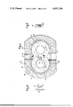
- FIG. 1 is a cross-section through a gear pump according to the present invention
- FIG. 2 is a cross-section taken along the line II--II of FIG. 1;
- FIG. 3 is a partial cross-sectional taken along the line III--III of FIG. 1;
- FIG. 4 is a cross-section through a second embodiment of a gear pump according to the present invention.
- FIG. 5 is a cross-section taken along the line V--V of FIG. 4;
- FIG. 6 is a partial cross-section taken along the line VI--VI of FIG. 4;
- FIGS. 7 and 8 illustrate details of the embodiment shown in FIG. 1;
- FIG. 9 is a modification of the embodiment shown in FIG. 4.
- the gear pump according to the present invention may comprise a central housing part 10 formed with two intersecting bores 13 and 14 to provide in the housing part 10 a chamber 15 having a cross-section substantially in the form of a figure 8.
- the chamber 15 is closed at opposite ends by end walls or covers 11 and 12 which are connected to the central housing part 10 by means not shown in the drawing, for instance by screws.
- Two bearing bodies 16 and 17 are arranged in the bore 13 of the housing in which the trunions 18 and 19 of an external gear 20 are rotatably mounted.
- the gear 20 meshes with a likewise external gear 21 which is rotatably mounted in two bearings, similar to the bearings 16 and 17, arranged in the bore 14 and not specifically designated in the drawing.
- a high pressure bore 22 extends from the outer periphery of the housing 10 into the chamber 15 and opposite and axially aligned with the high pressure bore 22 is a low pressure bore 23 leading from the chamber 15 to the outside of the housing 10.
- control grooves 24 and 25 are formed at the side faces of the bearing bodies 16 and 17 which are directed toward the side faces of the gears 21 and 22 and these control grooves 24 and 25 are in communication with the high pressure bore 22 and extend from the latter in the direction of the plane at which the two bearing bodies 16 and 17 engage each other toward, but short of, a plane which includes the axes of the trunions of the gears.
- a bore 26 extends, from the end of the control groove 24 distant from the high pressure bore 22, into the bearing body 17, substantially parallel to the aforementioned engaging plane, toward the low pressure bore 23, slightly beyond the plane passing through the centers of the trunions of the two gears 20 and 21.
- a throttle bore 27 extends from the inner end of bore 26 and opens at the region of the side face of the bearing body 17 directed toward the gears at which the gear teeth move away from each other so that the interstices between engaging teeth increase.
- the increasing interstices between engaging gear teeth is closed toward the suction, respectively the pressure side by the points or lines D 1 and D 2 , which points move during rotation of the gears along the line e. If the flanks of the gears engage without play, then the corresponding sealing points are D' 1 and D' 2 , as shown in FIG. 8.
- the end of the bore communicating with the aforementioned interstices between the engaging teeth is located radially outside of the root circle of the gear 21 but also in such a way that it can just be covered by the tip of a tooth of the gear 20.
- the mouth of the throttle bore is positioned in such a way that, during the opening of the interstices between two engaging gear teeth at the end E 2 of the teeth engagement, the throttle bore 17 is just covered by a tooth of the gear 21 or 20. In this way passage of pressure fluid from the high pressure side into the mentioned interstices is prevented.
- the mouth of the throttle bore 27 is located slightly towards the left of the engaging plane between the two bearing bodies 16 and 17.
- FIGS. 4 and 5 differs from the above-described embodiments in that in this embodiment the bushing shaped bearing bodies 16 and 17 are replaced by a one-piece bearing body 30 which is substantially in the form of a spectacle frame. A corresponding one-piece bearing body 31 is located at the opposite side of the gears 20 and 21.
- a substantially kidney-shaped groove 32 is provided in the embodiment shown in FIGS. 4 and 5 which is located between the inner end of the high pressure bore 22 and a plane connecting the centers of the trunions of the two gears 20 and 21.
- a bore 26' with a throttle bore 27' leads again from the kidney-shaped groove 32 to the region in which the interstices between the engaging gear teeth increase during rotation of the gear.
- the kidney-shaped groove 32 is located in a region in which high pressure prevails so that the same action, as described above in connection with the embodiment shown in FIGS. 1 and 2, will occur with the embodiment shown in FIGS. 4 and 5.
- FIG. 9 shows a modification of the arrangement illustrated in FIGS. 4-6 in which the throttle passage is formed as a groove 34 with a throttling cross-section.
- This groove extends in the same direction as the bore 26' and ends in the region in which the interstices between the engaging gears increase.
- the groove 34 is formed on the side face of the bearing body which is directed towards the corresponding side face of the respective gear.
- a throttle passage may also be arranged on opposite sides of the gears and even on opposite sides of the symmetry or engaging plane of the bearing bodies. Essentially is only that the throttling connection leads from the high pressure side of the machine to the mentioned region.
Landscapes
- Engineering & Computer Science (AREA)
- Mechanical Engineering (AREA)
- General Engineering & Computer Science (AREA)
- Rotary Pumps (AREA)
Applications Claiming Priority (2)
| Application Number | Priority Date | Filing Date | Title |
|---|---|---|---|
| DT2554105 | 1975-12-02 | ||
| DE2554105A DE2554105C2 (de) | 1975-12-02 | 1975-12-02 | Zahnradmaschine (Pumpe oder Motor) |
Publications (1)
| Publication Number | Publication Date |
|---|---|
| US4097206A true US4097206A (en) | 1978-06-27 |
Family
ID=5963231
Family Applications (1)
| Application Number | Title | Priority Date | Filing Date |
|---|---|---|---|
| US05/743,289 Expired - Lifetime US4097206A (en) | 1975-12-02 | 1976-11-18 | Gear pump or motor with bypass throttle passage to prevent cavitation |
Country Status (4)
| Country | Link |
|---|---|
| US (1) | US4097206A (it) |
| DE (1) | DE2554105C2 (it) |
| GB (1) | GB1556054A (it) |
| IT (1) | IT1064407B (it) |
Cited By (24)
| Publication number | Priority date | Publication date | Assignee | Title |
|---|---|---|---|---|
| US4480970A (en) * | 1981-05-30 | 1984-11-06 | Rolls-Royce Limited | Self priming gear pump |
| US4556373A (en) * | 1984-09-04 | 1985-12-03 | Eaton Corporation | Supercharger carryback pulsation damping means |
| US4569646A (en) * | 1984-09-04 | 1986-02-11 | Eaton Corporation | Supercharger carry-over venting means |
| US4902202A (en) * | 1987-07-29 | 1990-02-20 | Hydreco, Inc. | Variable discharge gear pump with energy recovery |
| US5417556A (en) * | 1994-03-08 | 1995-05-23 | Alliedsignal Inc. | Bearing for gear pump |
| US6042352A (en) * | 1998-08-12 | 2000-03-28 | Argo-Tech Corporation | Bearing with pulsed bleed configuration |
| US6286988B1 (en) * | 1996-04-16 | 2001-09-11 | Hartmut Hasse | Extrusion head having toothed wheels with mixing device and adjustable shear effect |
| US20070178003A1 (en) * | 2005-11-22 | 2007-08-02 | Parker-Hannifin Corporation | Gear pump with ripple chamber for low noise and pressure ripples |
| US20080025862A1 (en) * | 2006-03-10 | 2008-01-31 | Markus Hanst | External toothed wheel pump comprising a relieving pocket |
| US20080166254A1 (en) * | 2006-09-28 | 2008-07-10 | Martin Jordan | Hydraulic device |
| US20080240968A1 (en) * | 2004-02-13 | 2008-10-02 | Chiu Hing L | Low Cost Gear Fuel Pump |
| US20090148333A1 (en) * | 2007-12-11 | 2009-06-11 | Hamilton Sundstrand Corporation | Gear pump cavitation reduction |
| CN103026068A (zh) * | 2010-06-14 | 2013-04-03 | 舍弗勒技术股份两合公司 | 外齿轮泵 |
| US20140086779A1 (en) * | 2012-09-24 | 2014-03-27 | Robert Bosch Gmbh | Gear machine having a low-pressure connection deviating from the circular shape |
| US8790090B2 (en) | 2011-07-26 | 2014-07-29 | Hamilton Sundstrand Corporation | Priming of gear pump in alternative attitudes |
| US8801410B2 (en) | 2011-02-25 | 2014-08-12 | Hamilton Sundstrand Corporation | Coupling shaft for gear pump |
| US8814547B2 (en) | 2011-02-25 | 2014-08-26 | Hamilton Sundstrand Corporation | Seal retaining sleeve for gear pump |
| WO2014171744A1 (en) * | 2013-04-17 | 2014-10-23 | Nag-Bok Lim | A silent gear pump or motor suppressing troubles of trapping fluid |
| US8911222B2 (en) | 2011-02-25 | 2014-12-16 | Hamilton Sundstrand Corporation | Input shaft assembly for gear pump |
| US8992192B2 (en) | 2011-02-25 | 2015-03-31 | Hamilton Sundstrand Corporation | Input shaft lubrication for gear pump |
| US9303644B2 (en) | 2013-11-26 | 2016-04-05 | Woodward, Inc. | Gear pump bearing dam |
| CN106567910A (zh) * | 2016-11-14 | 2017-04-19 | 河南蒲瑞精密机械有限公司 | 一种动压齿轮传动装置 |
| US9677559B2 (en) | 2011-02-25 | 2017-06-13 | Hamilton Sundstrand Corporation | Bearing face geometry for gear pump |
| US10443597B2 (en) | 2016-01-12 | 2019-10-15 | Hamilton Sundstrand Corporation | Gears and gear pumps |
Families Citing this family (3)
| Publication number | Priority date | Publication date | Assignee | Title |
|---|---|---|---|---|
| DE4338876C2 (de) * | 1993-11-13 | 2001-10-18 | Mannesmann Rexroth Ag | Hydraulische Zahnradmaschine (Hydropumpe oder Hydromotor) |
| DE19543962A1 (de) * | 1995-11-25 | 1997-05-28 | Bosch Gmbh Robert | Hydraulische Fahrzeugbremsanlage mit Radschlupfregeleinrichtung |
| DE19721621C2 (de) * | 1997-05-23 | 2000-02-03 | Bosch Gmbh Robert | Zahnradmaschine |
Citations (4)
| Publication number | Priority date | Publication date | Assignee | Title |
|---|---|---|---|---|
| US2981200A (en) * | 1956-10-05 | 1961-04-25 | Parker Appliance Co | Gear pump structure |
| US3113524A (en) * | 1961-12-26 | 1963-12-10 | Roper Hydraulics Inc | Gear pump with trapping reliefs |
| US3137238A (en) * | 1961-12-11 | 1964-06-16 | Clark Equipment Co | Pump or motor |
| US3474736A (en) * | 1967-12-27 | 1969-10-28 | Koehring Co | Pressure loaded gear pump |
Family Cites Families (2)
| Publication number | Priority date | Publication date | Assignee | Title |
|---|---|---|---|---|
| CH396642A (de) * | 1960-04-29 | 1965-07-31 | Reiners U Wiggermann | Zahnrad- Verdrängungsmaschine |
| DE1553090A1 (de) * | 1965-12-10 | 1970-01-08 | Kracht Pumpen Motoren | Zahnradpumpe oder -motor fuer hohe Druecke |
-
1975
- 1975-12-02 DE DE2554105A patent/DE2554105C2/de not_active Expired
-
1976
- 1976-11-09 GB GB46641/76A patent/GB1556054A/en not_active Expired
- 1976-11-18 US US05/743,289 patent/US4097206A/en not_active Expired - Lifetime
- 1976-11-25 IT IT29743/76A patent/IT1064407B/it active
Patent Citations (4)
| Publication number | Priority date | Publication date | Assignee | Title |
|---|---|---|---|---|
| US2981200A (en) * | 1956-10-05 | 1961-04-25 | Parker Appliance Co | Gear pump structure |
| US3137238A (en) * | 1961-12-11 | 1964-06-16 | Clark Equipment Co | Pump or motor |
| US3113524A (en) * | 1961-12-26 | 1963-12-10 | Roper Hydraulics Inc | Gear pump with trapping reliefs |
| US3474736A (en) * | 1967-12-27 | 1969-10-28 | Koehring Co | Pressure loaded gear pump |
Cited By (37)
| Publication number | Priority date | Publication date | Assignee | Title |
|---|---|---|---|---|
| US4480970A (en) * | 1981-05-30 | 1984-11-06 | Rolls-Royce Limited | Self priming gear pump |
| US4556373A (en) * | 1984-09-04 | 1985-12-03 | Eaton Corporation | Supercharger carryback pulsation damping means |
| US4569646A (en) * | 1984-09-04 | 1986-02-11 | Eaton Corporation | Supercharger carry-over venting means |
| US4902202A (en) * | 1987-07-29 | 1990-02-20 | Hydreco, Inc. | Variable discharge gear pump with energy recovery |
| US5417556A (en) * | 1994-03-08 | 1995-05-23 | Alliedsignal Inc. | Bearing for gear pump |
| US6286988B1 (en) * | 1996-04-16 | 2001-09-11 | Hartmut Hasse | Extrusion head having toothed wheels with mixing device and adjustable shear effect |
| US6042352A (en) * | 1998-08-12 | 2000-03-28 | Argo-Tech Corporation | Bearing with pulsed bleed configuration |
| US20080240968A1 (en) * | 2004-02-13 | 2008-10-02 | Chiu Hing L | Low Cost Gear Fuel Pump |
| US20070178003A1 (en) * | 2005-11-22 | 2007-08-02 | Parker-Hannifin Corporation | Gear pump with ripple chamber for low noise and pressure ripples |
| US20080025862A1 (en) * | 2006-03-10 | 2008-01-31 | Markus Hanst | External toothed wheel pump comprising a relieving pocket |
| US7654806B2 (en) * | 2006-03-10 | 2010-02-02 | Shwaebische Huettenwerke Automotive GmbH & Co. KG | External toothed wheel pump comprising a relieving pocket |
| US20080166254A1 (en) * | 2006-09-28 | 2008-07-10 | Martin Jordan | Hydraulic device |
| US8512018B2 (en) * | 2006-09-28 | 2013-08-20 | Trw Automotive Gmbh | Gear pump with pressure relief groove |
| US20090148333A1 (en) * | 2007-12-11 | 2009-06-11 | Hamilton Sundstrand Corporation | Gear pump cavitation reduction |
| US7878781B2 (en) * | 2007-12-11 | 2011-02-01 | Hamilton Sundstrand Corporation | Gear pump cavitation reduction |
| EP2071122A3 (en) * | 2007-12-11 | 2012-10-31 | Hamilton Sundstrand Corporation | Gear pump cavitation reduction |
| CN103026068B (zh) * | 2010-06-14 | 2016-04-27 | 舍弗勒技术股份两合公司 | 外齿轮泵 |
| CN103026068A (zh) * | 2010-06-14 | 2013-04-03 | 舍弗勒技术股份两合公司 | 外齿轮泵 |
| US9546655B2 (en) | 2011-02-25 | 2017-01-17 | Hamilton Sundstrand Corporation | Coupling shaft for gear pump |
| US8801410B2 (en) | 2011-02-25 | 2014-08-12 | Hamilton Sundstrand Corporation | Coupling shaft for gear pump |
| US8814547B2 (en) | 2011-02-25 | 2014-08-26 | Hamilton Sundstrand Corporation | Seal retaining sleeve for gear pump |
| US10024319B2 (en) | 2011-02-25 | 2018-07-17 | Hamilton Sundstrand Corporation | Method for lubricating a coupling shaft for gear pump |
| US8911222B2 (en) | 2011-02-25 | 2014-12-16 | Hamilton Sundstrand Corporation | Input shaft assembly for gear pump |
| US8992192B2 (en) | 2011-02-25 | 2015-03-31 | Hamilton Sundstrand Corporation | Input shaft lubrication for gear pump |
| US9677559B2 (en) | 2011-02-25 | 2017-06-13 | Hamilton Sundstrand Corporation | Bearing face geometry for gear pump |
| US8790090B2 (en) | 2011-07-26 | 2014-07-29 | Hamilton Sundstrand Corporation | Priming of gear pump in alternative attitudes |
| US20140086779A1 (en) * | 2012-09-24 | 2014-03-27 | Robert Bosch Gmbh | Gear machine having a low-pressure connection deviating from the circular shape |
| US9140258B2 (en) * | 2012-09-24 | 2015-09-22 | Robert Bosch Gmbh | Gear machine having a non-circular low-pressure connection |
| WO2014171567A1 (en) * | 2013-04-17 | 2014-10-23 | Nag-Bok Lim | Silent gear pump suppressing tooth contact noise |
| JP2016515683A (ja) * | 2013-04-17 | 2016-05-30 | リム ナグボクLIM, Nag−Bok | 遮蔽流体トラブルを改善した低ノイズギアポンプまたはモーター |
| US9945230B2 (en) | 2013-04-17 | 2018-04-17 | Nag-Bok Lim | Silent gear pump or motor suppressing troubles of trapping fluid |
| WO2014171744A1 (en) * | 2013-04-17 | 2014-10-23 | Nag-Bok Lim | A silent gear pump or motor suppressing troubles of trapping fluid |
| US9303644B2 (en) | 2013-11-26 | 2016-04-05 | Woodward, Inc. | Gear pump bearing dam |
| US9932980B2 (en) | 2013-11-26 | 2018-04-03 | Woodward, Inc. | Gear pump bearing dam |
| US10443597B2 (en) | 2016-01-12 | 2019-10-15 | Hamilton Sundstrand Corporation | Gears and gear pumps |
| CN106567910A (zh) * | 2016-11-14 | 2017-04-19 | 河南蒲瑞精密机械有限公司 | 一种动压齿轮传动装置 |
| CN106567910B (zh) * | 2016-11-14 | 2023-08-22 | 河南蒲瑞精密机械有限公司 | 一种动压齿轮传动装置 |
Also Published As
| Publication number | Publication date |
|---|---|
| IT1064407B (it) | 1985-02-18 |
| DE2554105A1 (de) | 1977-06-16 |
| DE2554105C2 (de) | 1984-04-05 |
| GB1556054A (en) | 1979-11-21 |
Similar Documents
| Publication | Publication Date | Title |
|---|---|---|
| US4097206A (en) | Gear pump or motor with bypass throttle passage to prevent cavitation | |
| US6068461A (en) | Vane type rotary pump having a discharge port with a tapered bearded groove | |
| US2293126A (en) | Gear pump or motor | |
| US3947163A (en) | Screw rotor machine with axially balanced hollow thread rotor | |
| US4767296A (en) | Trochoidal toothed oil pump with thin discharge channel communicating with discharge chamber | |
| US2884864A (en) | Pressure loaded pump, trapping grooves | |
| US5122335A (en) | Method of producing a gear for a ring pump | |
| CN207377794U (zh) | 一种摆线泵 | |
| US1976227A (en) | Gear pump | |
| JPH01247767A (ja) | 内接歯車モータ | |
| US4277230A (en) | Gear machine operable as pump or motor with axially spaced and circumferentially offset pair of gears | |
| US4881880A (en) | Drain for internal gear hydraulic device | |
| US2774309A (en) | Pump | |
| US3015282A (en) | Pump | |
| US4934911A (en) | Hydraulic rotary piston engine having inproved commutator valve | |
| US4132515A (en) | Crescent gear pump or motor having bearing means for supporting the ring gear | |
| US2671410A (en) | Gear pump | |
| CN220168136U (zh) | 一种内啮合齿轮泵 | |
| GB2315098A (en) | Rotary machine | |
| JPH0275783A (ja) | トロコイドポンプ | |
| CN2097295U (zh) | 内啮合内摆线油泵 | |
| CN215059277U (zh) | 一种变速旋转式回转减速器 | |
| JPH10122160A (ja) | ギアポンプ | |
| JPS63131877A (ja) | 内接歯車式回転ポンプ | |
| US2979036A (en) | Hydraulic rotary engine |